SERVICE MANUAL
Amplifier section
· Power output: 2 W + 2 W
· Input: Speaker cord with stereo miniplug (50 cm)
· Input impedance: 4.7 kilohms (at 1 kHz)
Speaker section
· System: Full-range, bass reflex type
· Speaker units: Magnetically shielded ø 39 mm
· Impedance: 8 ohms
· Rated input power: 2 W
· Maximum input power: 4 W
General
· Power requirement: Four R6 (size AA) batteries/DC 9 V
· Battery life (at TOTAL 10 mW output):
Approx. 24 hours Sony alkaline batteries LR6 (SG)
Approx. 8 hours Sony manganese batteries R6P (SR)
· Dimensions: Approx. 221
× 127 × 117 mm (8 3/4 × 5 ×
4 5/8 in.) (w/h/d) (during use)
Approx. 143
× 127 × 29 mm (5 3/4 × 5 × 1 3/16 in.)
(w/h/d) (folded)
· Mass: Approx. 260 g (9 oz.) not incl. batteries Approx.
350 g (12 oz.) incl. batteries
· Supplied accessories: AC power adaptor
AC- E90A (1), Carrying case (1), Plug adaptor (1)*
*For world model only.
Design and specifications are subject to change without
notice.
Features
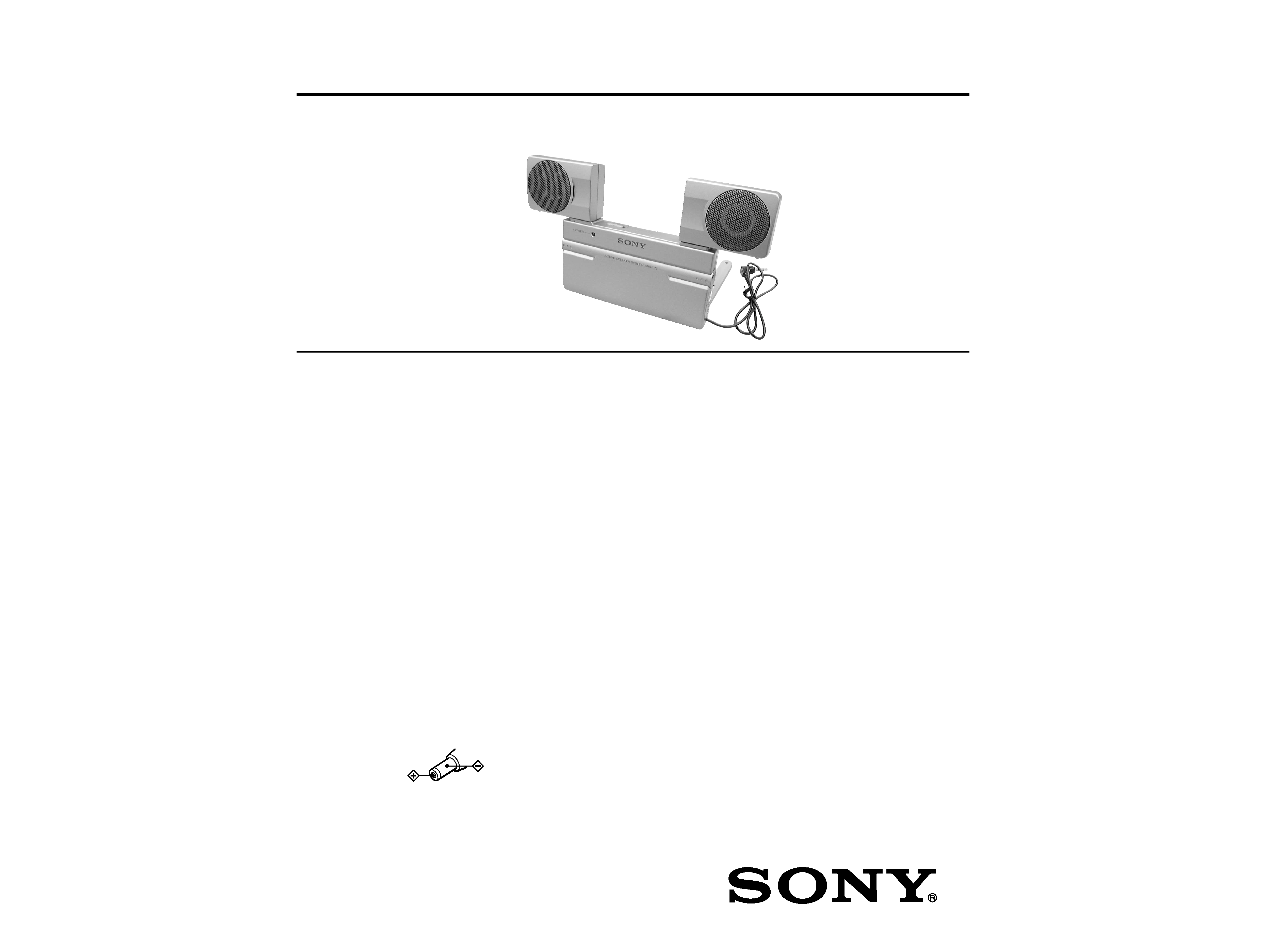
· The Sony SRS-T77 is a compact (CD case-sized) speaker
system with a built-in power amplifier. This system can be
connected to a Discman, WALKMAN*, headphone
stereo, etc.
· The SRS-T77 has a dual power supply system. When you
operate the SRS-T77 outdoors, use battery power, and
when you operate it indoors, use an AC power adaptor
(supplied).
Rich and powerful bass
· Power output of 2 W + 2 W
· The embedded MEGA BASS delivers rich bass regardless
of the sound volume.
*WALKMAN is a registered trademark of Sony
Corporation.
Note on the AC power adaptor
Use only the AC-E90A (supplied) AC power adaptor.
Do not use any other AC power adaptor.
Polarity of the plug
ACTIVE SPEAKER SYSTEM
US Model
Canadian Model
Tourist Model
SRS-T77
Ver 1.0 2001.02
9-927-993-11
Sony Corporation
2001B0500-1
Audio Entertainment Group
C
2001.2
General Engineering Dept.
Notes on chip component replacement
· Never reuse a disconnected chip component.
· Notice that the minus side of a tantalum capacitor may be dam-
aged by heat.
SPECIFICATIONS
2
SRS-T77
SECTION 1
GENERAL
This section is extracted from
instruction manual.
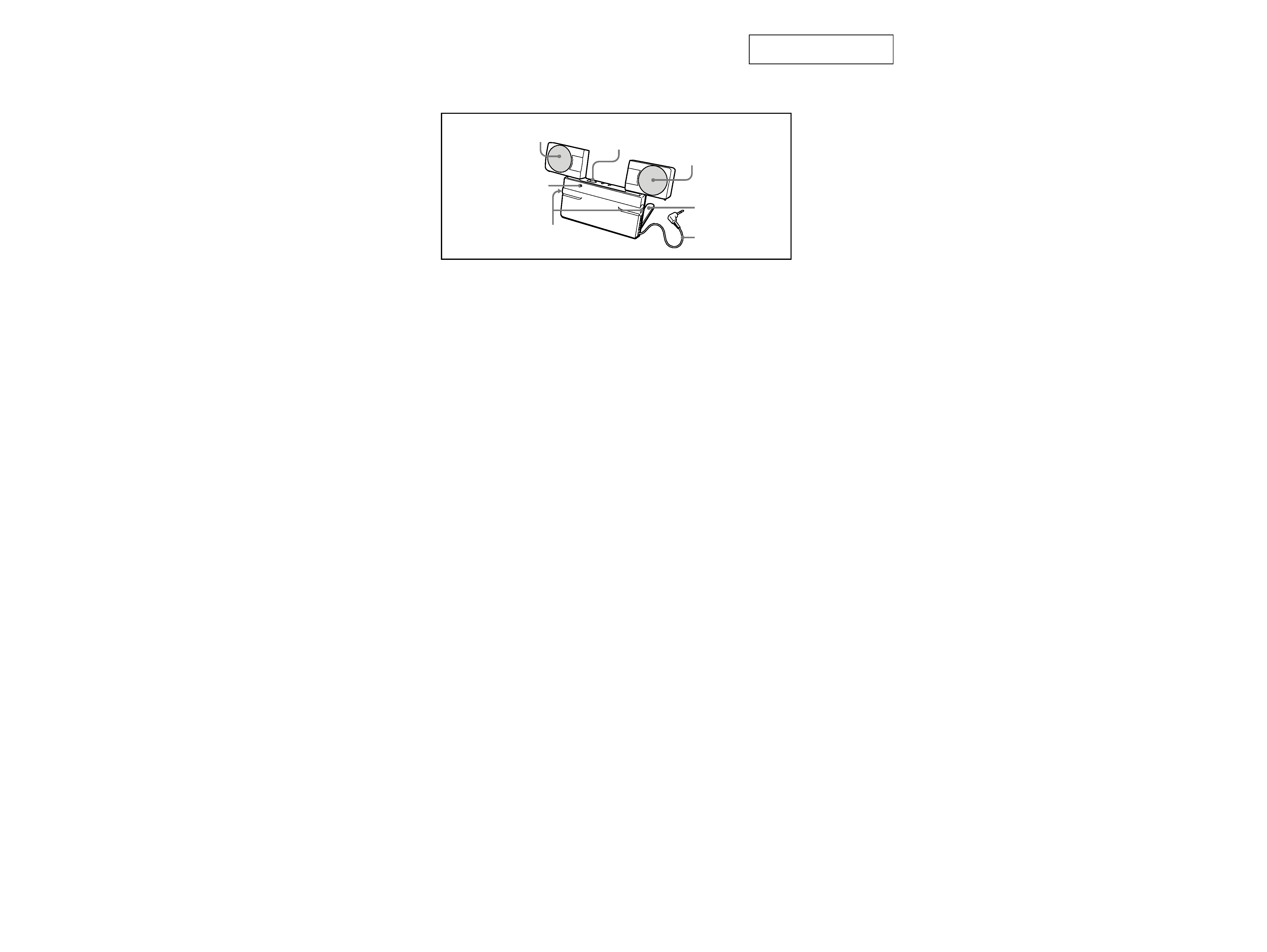
· LOCATION OF CONTROL
Right speaker
Left speaker
POWER switch
Speaker cord
Stand
Bass reflex duct
POWER indicator
3
SRS-T77
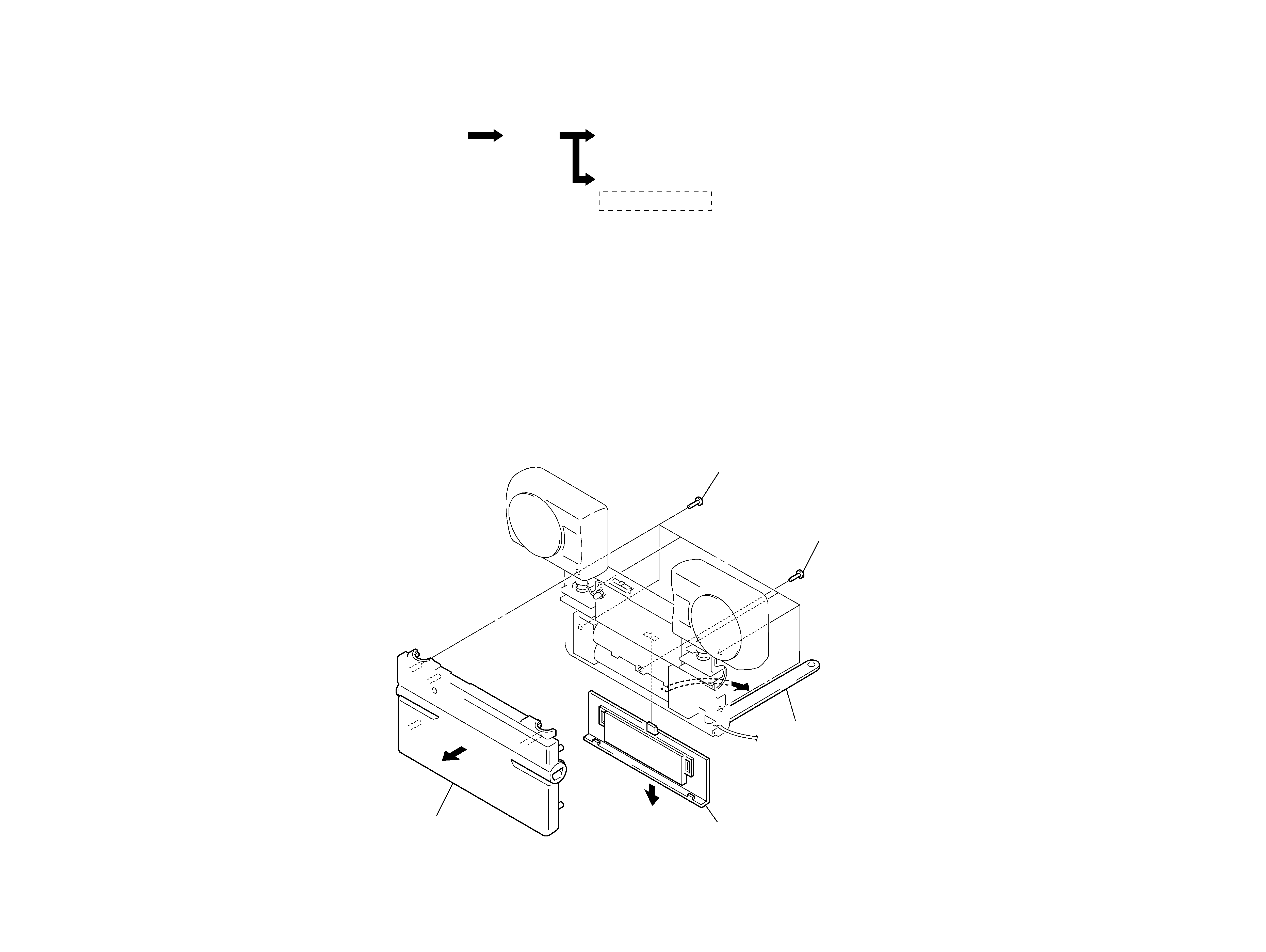
2-2.
CASE, FRONT
· This set can be disassembled in the order shown below.
2-1.
DISASSEMBLY FLOW
SECTION 2
DISASSEMBLY
Note: Follow the disassembly procedure in the numerical order given.
Set
Speaker unit (SP1) (L ch)/(SP2) (R ch)
AMP board, Jack board
Draw Around Lead Wires
Case, Front
3
six screws
(P2.6
× 10)
4
screw
(P2
× 5)
1
Open stand
in the direction of arrow A.
2
lid, battery case
5
case, front
A
4
SRS-T77
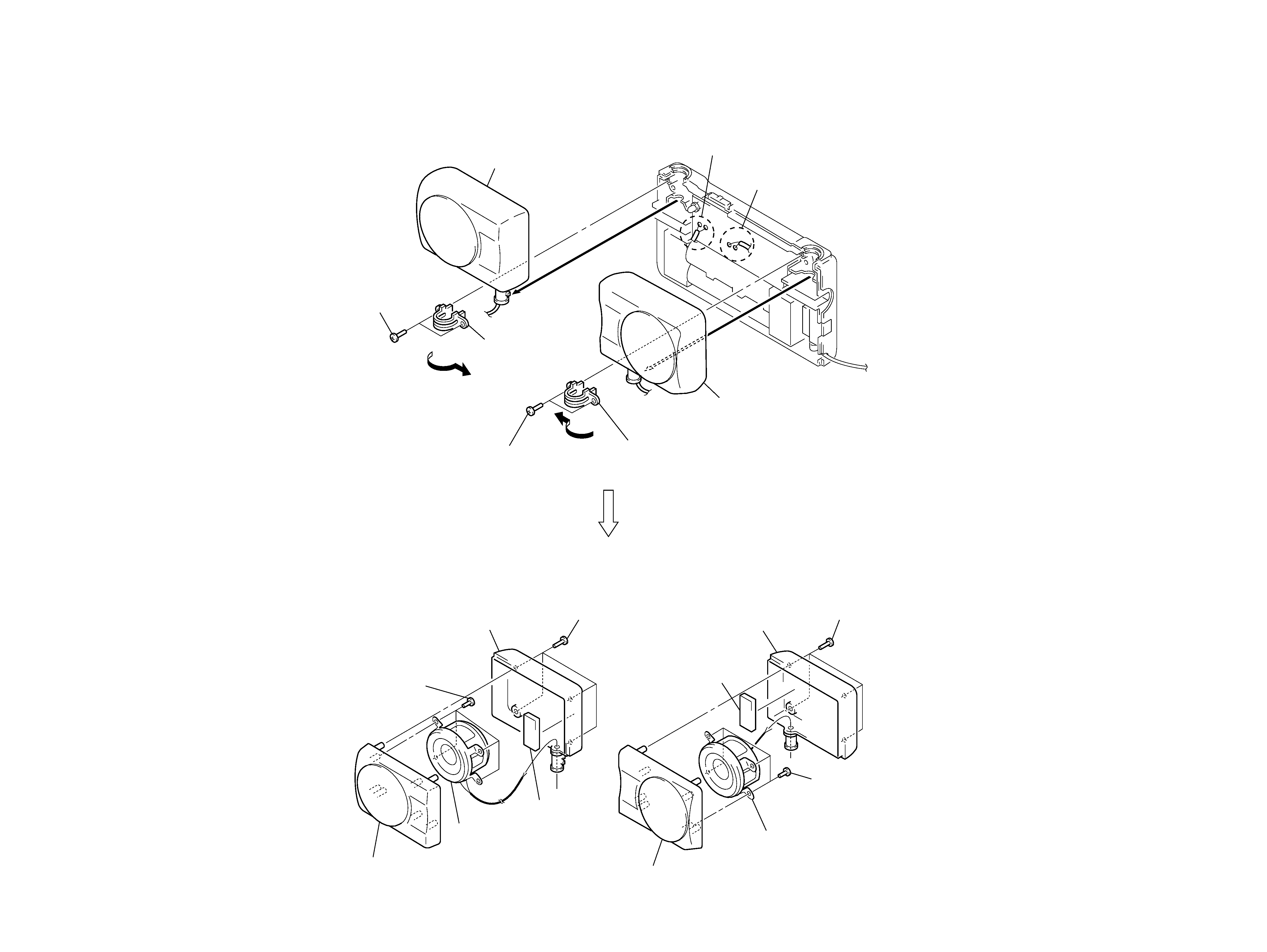
2-3.
SPEAKER UNIT (SP1) (L ch)/(SP2) (R ch)
1
Remove two solders of lead
from speaker unit (SP1) (L ch).
6
Remove two solders of lead
from speaker unit (SP2) (R ch).
2
two screws
(P2.6
× 6)
7
two screws
(P2.6
× 6)
4
Remove "holder, rotary shaft"
in the direction of arrow A.
A
9
Remove "holder, rotary shaft"
in the direction of arrow B.
8
B
3
5
speaker unit (L ch) assy
0
speaker unit (R ch) assy
Note:
It is not necessary to remove speaker unit (L ch) assy
to remove speaker unit (R ch) assy.
qf
four screws
(P2.6
× 6)
w;
four screws
(P2.6
× 6)
qj
four screws
(P2.6
× 6)
qa
four screws
(P2.6
× 6)
qs
cabinet (L), rear
qk
cabinet (R), rear
qh
cabinet (L) assy, front
ws
cabinet (R) assy, front
qg
speaker unit (SP1) (L ch)
wa
speaker unit (SP2) (R ch)
qd
absorbent, acoustic
ql
absorbent, acoustic
Note:
It is not necessary to remove speaker unit (SP1) (L ch)
to remove speaker unit (SP2) (R ch).
SRS-T77
5
5
SECTION 3
DIAGRAMS
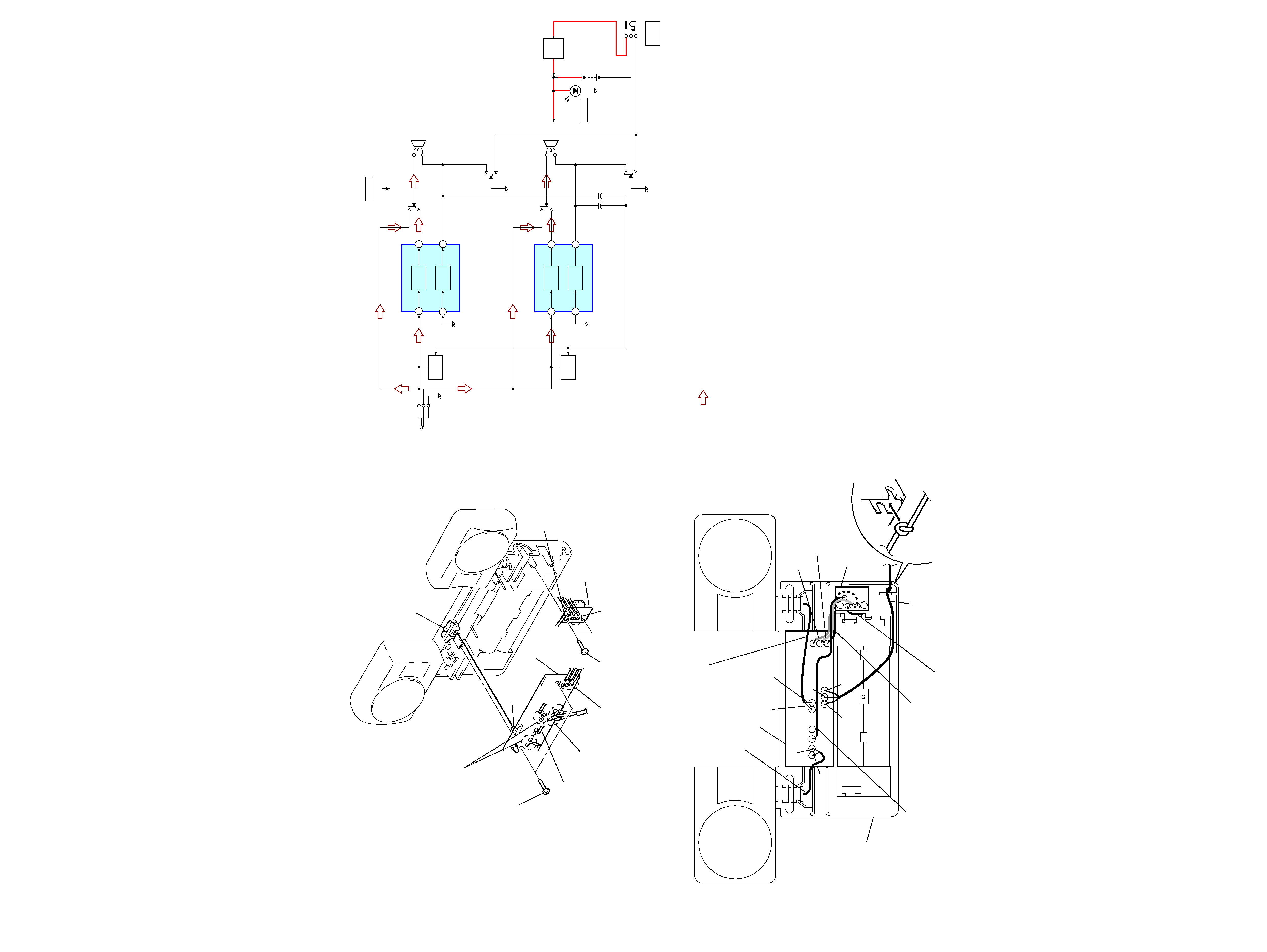
3-1.
BLOCK DIAGRAM
2-4.
AMP BOARD, JACK BOARD
2-5.
DRAW AROUND LEAD WIRES
2
two screws
(P2
× 5)
3
AMP board
S1
knob, switch
1
Remove four solders of lead
from speaker unit (SP1/SP2).
1
Remove two solders of lead (yellow, brown)
from jack board and solder of lead (red)
from "spring, plug battery".
4
Remove two solders of lead (yellow, brown)
from AMP board and solder of lead (black)
from "spring, minus battery".
4
Remove solder
of lead.
6
jack board
1
Remove three solders of cord (with plug).
1
Remove solder of lead.
5
two screws
(P2
× 5)
Note 3: When installation AMP board,
fit switch (S1) and "knob, switch".
Note 1: When installation leads and assembling set,
refer to DRAW AROUND LEAD WIRE.
Note 2: It is not necessary to remove AMP board
to remove jack board.
+
Note 1: It is possible that lead wire are caught between the "case, front" and "case, rear" and cut.
Draw around lead wires as shown in the figure.
Note 2: Put the knot of the cord (with plug)
in the groove of "case, rear".
lead wire
(speaker unit (SP2) (R ch)
-AMP board)
lead wire
(speaker unit (SP1) (L ch)
-AMP board)
lead wire (red)
(AMP board-"spring, plus battery")
lead wire (yellow)
(AMP board-jack board)
lead wire (blown)
(AMP board-jack board)
lead wire (black)
(jack board-"spring, minus battery")
cord (with plug)
"case, rear"
lead wire
(AMP board condenser (C22) minus side
-jack board)
jack board
AMP board
red
natural color
natural color
natural color
red
green
green
· SIGNAL PATH
: LINE INPUT
S1 (1/4)
S1 (2/4)
S1 (3/4)
S1 (4/4)
B+
SP1
(L-CH)
SP2
(R-CH)
P1
(LINE INPUT)
POWER AMP
IC1
OUT1
IN1+
POWER
AMP
19
12
OUT2
IN2+
POWER
AMP
MUTING
Q1
MUTING
Q2
2
9
POWER AMP
IC2
OUT1
IN1+
POWER
AMP
19
12
OUT2
IN2+
POWER
AMP
2
9
+
+
JK1
DC IN 9V
!
DRY BATTERY
SIZE "AA"
(IEC DESIGNATION R6)
4PCS. 6V
D2
POWER
S1
POWER
OFF/DIRECT
ON
LIMITER
Q3