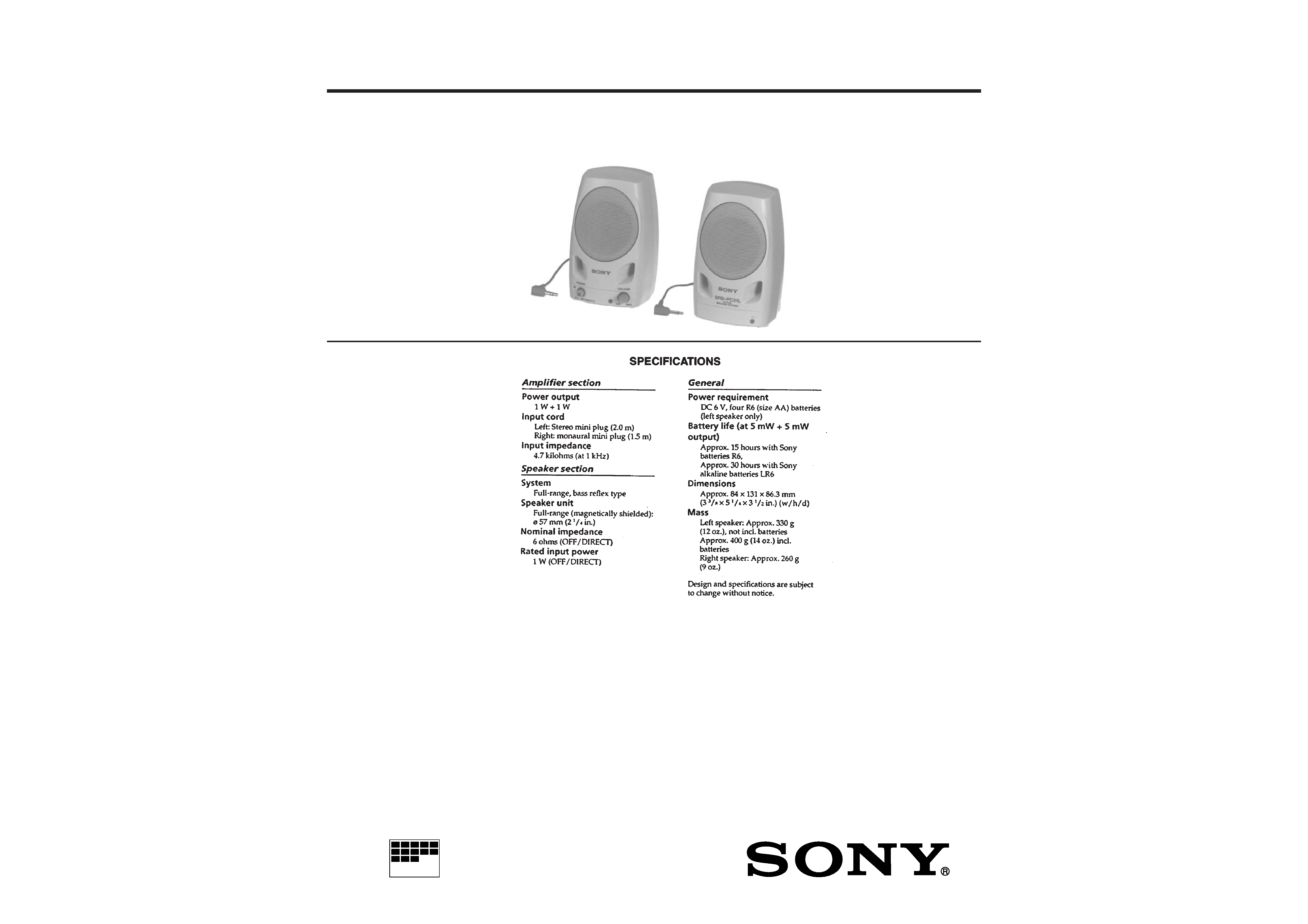
ACTIVE SPEAKER SYSTEM
MICROFILM
AEP Model
E Model
SERVICE MANUAL
SRS-PC21L
2
This section is extracted from
instruction manual.
SECTION 1
GENERAL
SECTION 3
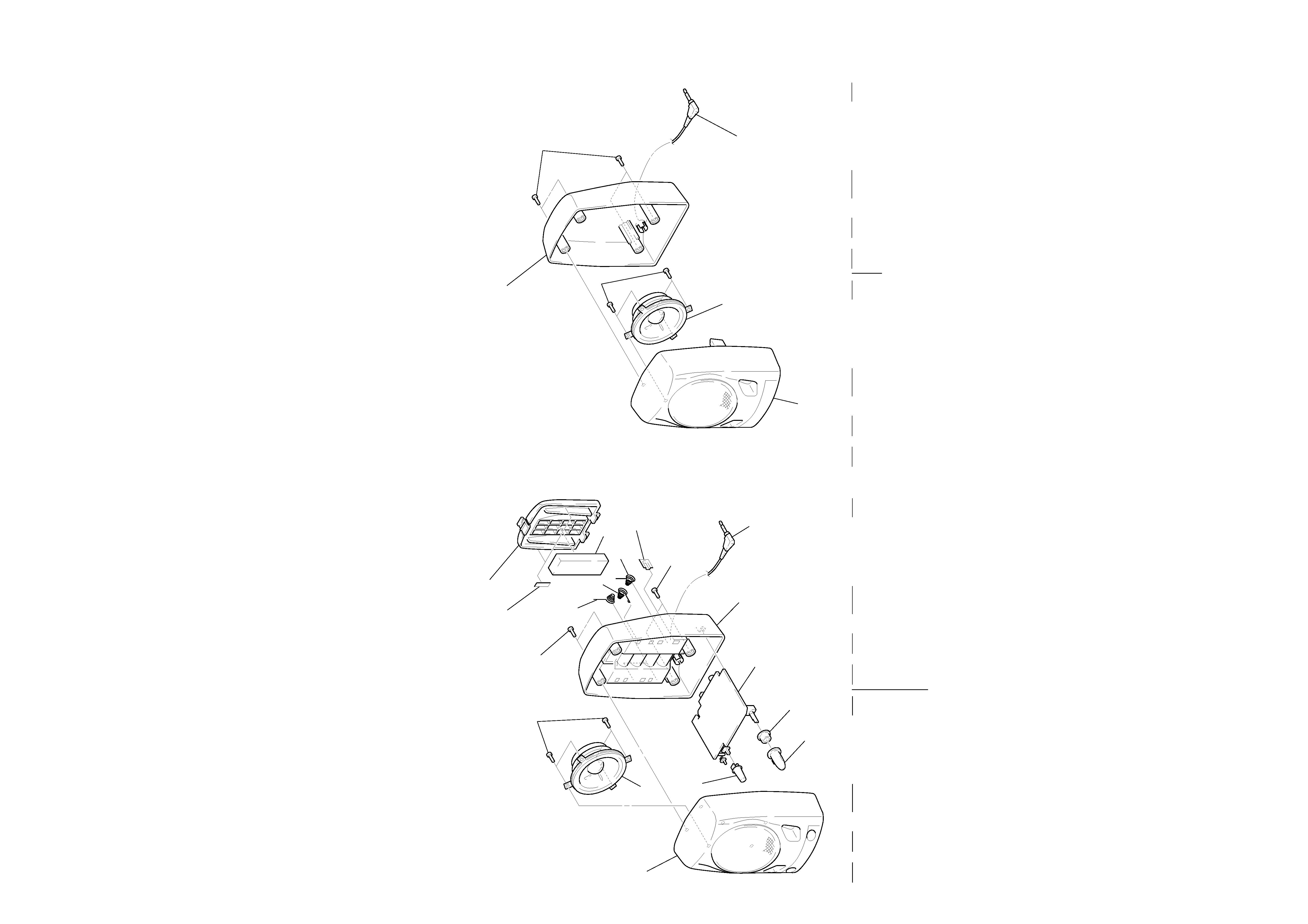
EXPLODED VIEWS
· Items marked "*" are not stocked since they
are seldom required for routine service. Some
delay should be anticipated when ordering these
items.
· The mechanical parts with no reference num-
ber in the exploded views are not supplied.
NOTE:
· -XX and -X mean standardized parts, so they
may have some difference from the original one.
· Color Indication of Appearance Parts
Example:
KNOB, BALANCE (WHITE) . . . (RED)
Parts Color
Cabinet's Color
Ref. No.
Part No.
Description
Remark
Ref. No.
Part No.
Description
Remark
(1) CABINET SECTION (L)
1
X-4947-114-1 CABINET (L) ASSY, FRONT
2
7-685-645-79 SCREW +BVTP 3X6 TYPE2 N-S
3
4-980-945-21 LID, BATTERY CASE
4
4-308-878-XX CUSHION
5
3-895-784-01 SPRING
6
4-967-264-01 SPRING (MINUS), BATTERY COIL
7
4-941-496-01 TERMINAL, BATTERY
8
7-685-135-19 SCREW +P 2.6X10 TYPE2 SLIT
9
4-980-943-21 CABINET (L), REAR
*10
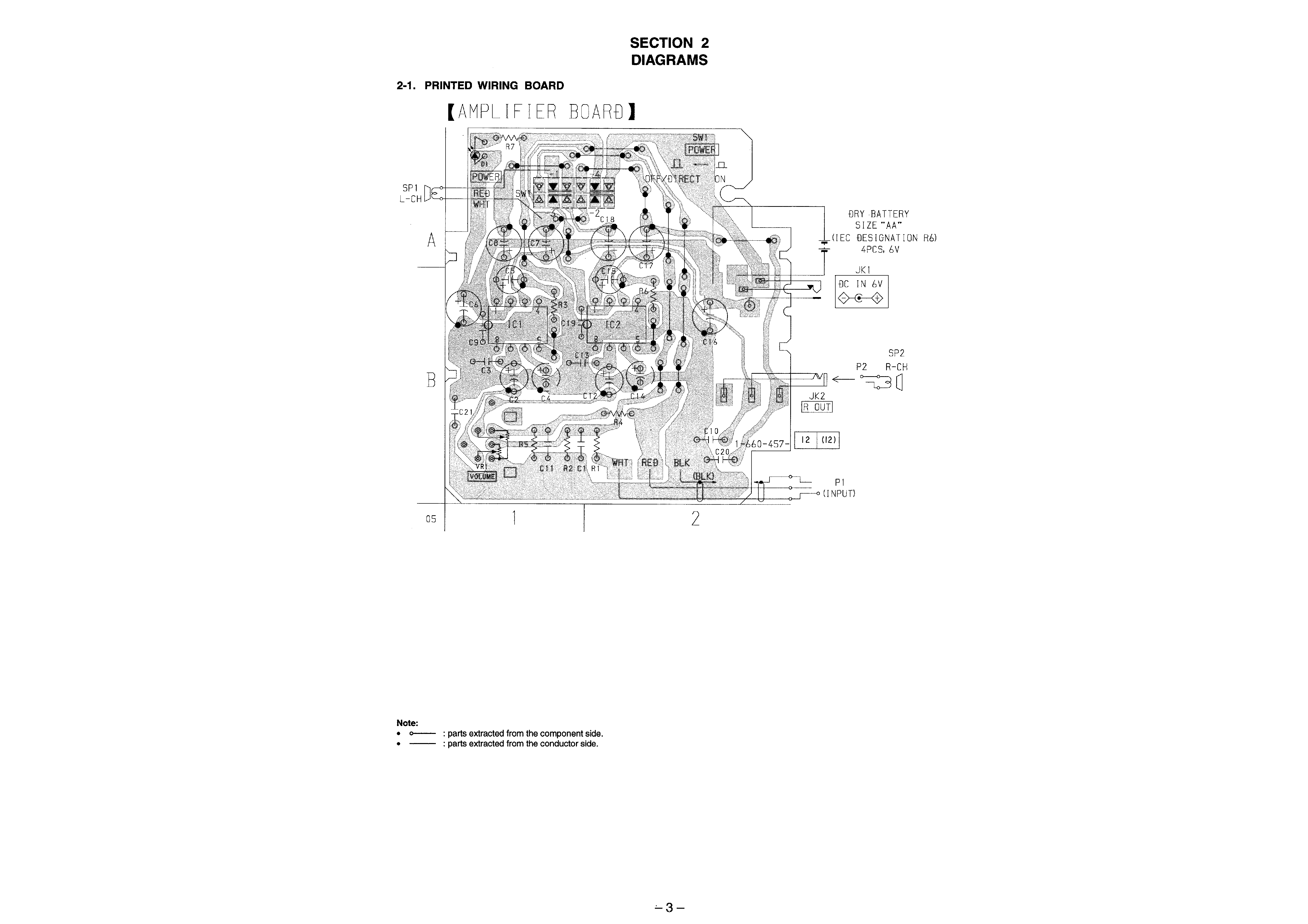
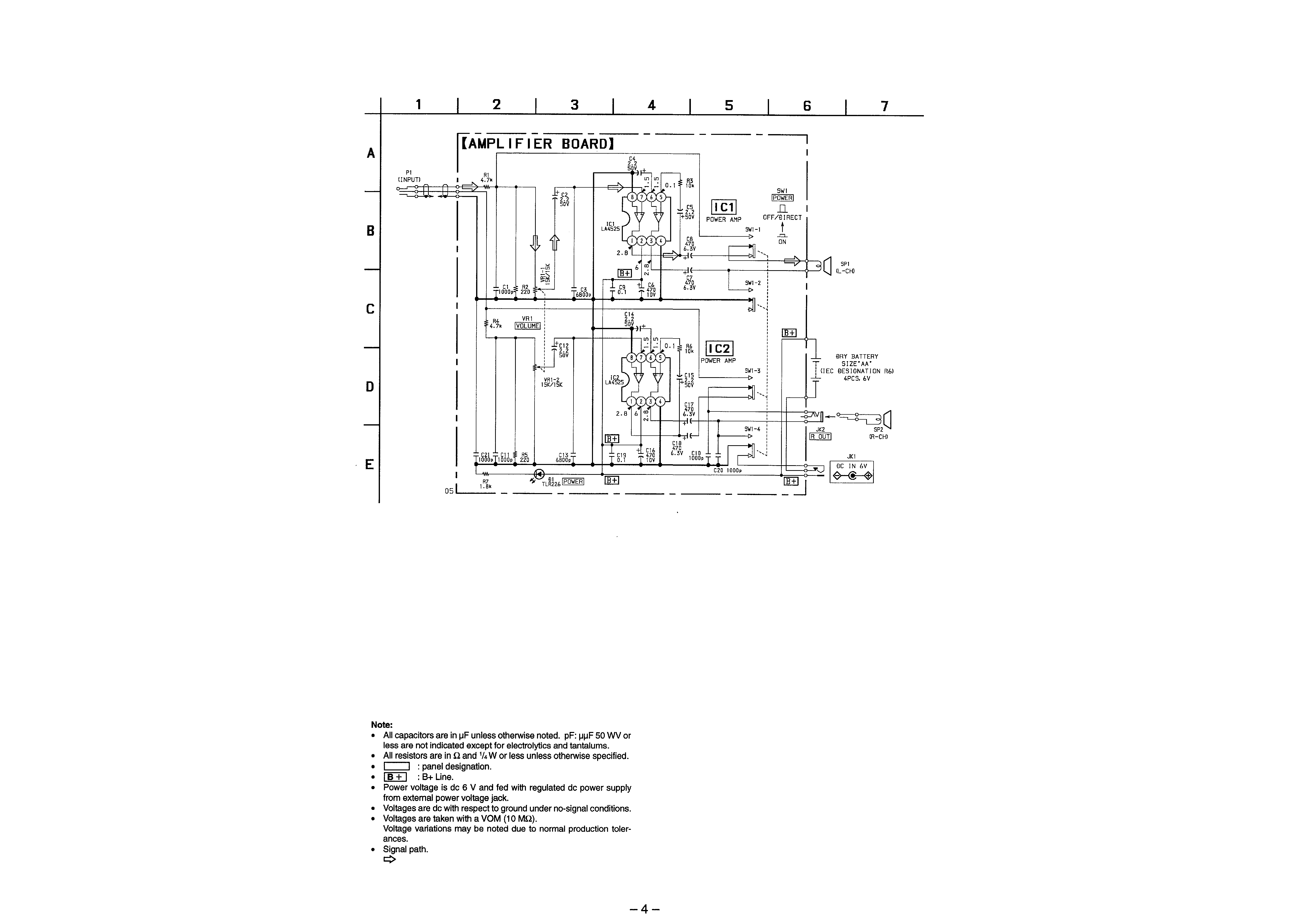
1-660-457-11 AMPLIFIER BOARD
11
4-980-946-21 BUTTON (POWER)
12
2-141-216-01 SPACER (VOL)
13
4-980-949-21 KNOB, VOLUME
14
3-831-441-11 CUSHION, CABINET UPPER 10X7X0.5
P1
1-559-891-41 CORD (WITH PLUG)(L)
SP1
1-505-281-11 SPEAKER (057F005)(L)
3
14
8
2
5
5
4
7
8
9
10
12
13
11
1
6
P1
SP1
53
54
52
51
SP2
P2
(2) CABINET SECTION (R)
51
X-4949-021-1 CABINET (R) ASSY, FRONT
52
7-685-645-79 SCREW +BVTP 3X6 TYPE2 N-S
53
4-980-944-21 CABINET (R), REAR
54
7-685-135-19 SCREW +P 2.6X10 TYPE2 SLIT
P2
1-696-003-41 CORD (WITH PLUG)(R)
SP2
1-505-281-11 SPEAKER (057F005)(R)
Ref. No.
Part No.
Description
Remark
Ref. No.
Part No.
Description
Remark
5
6