SERVICE MANUAL
ACTIVE SPEAKER SYSTEM
US Model
Canadian Model
AEP Model
UK Model
SPECIFICATIONS
SRS-NWM10
Ver. 1.0 2005.11
9-879-975-01
2005K05-1
© 2005.11
Sony Corporation
Personal Audio Division
Published by Sony Engineering Corporation
Speaker section
Speaker system
39 mm, Full range, magnetically
shielded
Enclosure type
Bass reflex
Impedance
4
Rated input power
2 W
Maximum input power
3 W
Amplifier section
Rated output
2 W + 2 W
(10% T.H.D., 1 kHz, 4
)
Audio input
Multiple connector
× 1
Stereo minijack
× 1
Data input/output
Multiple connector
× 1
Input impedance
Multiple connector 6.5 k
(at 1 kHz)
Stereo minijack 8.0 k
(at 1 kHz)
General
Power
Three R6 (size AA) batteries, DC 5.2
V (supplied AC power adaptor)
Dimensions (w/h/d)
Approx. 242
× 137 × 58 mm
(9 5/8
× 5 1/
2
× 2 3/
8 in.)
Mass
Approx. 560 g (1 lb. 4 oz.)
including batteries
Supplied accessories
Attachment for NW-A1000 series (1)
Attachment for NW-A3000 series (1)
Carrying pouch (1)
Power cord (1)
AC power adaptor (1)
Operating Instructions (1)
Design and specifications are subject to change without
notice.
Battery life
(5 mW + 5 mW output, illumination off)
Battery type
Usage time
Sony alkaline battery LR6 (SG)
Approx. 80 hours*
Sony manganese battery R6
Approx. 35 hours*
* Usage time stated above may vary according to the temperature
or conditions of use.
* Battery life will be shorter when the illumination is on.
Note on the AC power adaptor
Use only the supplied AC power adaptor. Do not use any
other AC power adaptor to avoid damaging the speaker.
Polarity of the plug

2
SRS-NWM10
UNLEADED SOLDER
Boards requiring use of unleaded solder are printed with the lead-
free mark (LF) indicating the solder contains no lead.
(Caution: Some printed circuit boards may not come printed with
the lead free mark due to their particular size)
: LEAD FREE MARK
Unleaded solder has the following characteristics.
· Unleaded solder melts at a temperature about 40 °C higher
than ordinary solder.
Ordinary soldering irons can be used but the iron tip has to be
applied to the solder joint for a slightly longer time.
Soldering irons using a temperature regulator should be set to
about 350
°C.
Caution: The printed pattern (copper foil) may peel away if
the heated tip is applied for too long, so be careful!
· Strong viscosity
Unleaded solder is more viscou-s (sticky, less prone to flow)
than ordinary solder so use caution not to let solder bridges
occur such as on IC pins, etc.
· Usable with ordinary solder
It is best to use only unleaded solder but unleaded solder may
also be added to ordinary solder.
ATTENTION AU COMPOSANT AYANT RAPPORT
À LA SÉCURITÉ!
LES COMPOSANTS IDENTIFIÉS PAR UNE MARQUE 0 SUR
LES DIAGRAMMES SCHÉMATIQUES ET LA LISTE DES
PIÈCES
SONT
CRITIQUES
POUR
LA
SÉCURITÉ
DE
FONCTIONNEMENT. NE REMPLACER CES COM- POSANTS
QUE PAR DES PIÈCES SONY DONT LES NUMÉROS SONT
DONNÉS DANS CE MANUEL OU DANS LES SUPPLÉMENTS
PUBLIÉS PAR SONY.
SAFETY-RELATED COMPONENT WARNING!!
COMPONENTS IDENTIFIED BY MARK 0 OR DOTTED LINE
WITH MARK 0 ON THE SCHEMATIC DIAGRAMS AND IN
THE PARTS LIST ARE CRITICAL TO SAFE OPERATION.
REPLACE THESE COMPONENTS WITH SONY PARTS WHOSE
PART NUMBERS APPEAR AS SHOWN IN THIS MANUAL OR
IN SUPPLEMENTS PUBLISHED BY SONY.
3
SRS-NWM10
SECTION 1
GENERAL
This section is extracted from
instruction manual.
D
C
B
1
(rear)
(arrière)
(parte posterior)
2
Three R6 (size AA) batteries
Trois piles R6 (format AA)
Tres pilas R6 (tamaño AA)
A
to DC IN 5.2 V jack
Vers la prise DC IN 5,2 V
a la toma DC IN 5,2 V
AC power adaptor (supplied)
Adaptateur secteur (fourni)
Adaptador de alimentación de ca
(suministrado)
to wall outlet
Vers la prise murale
a la toma de pared
E
(rear)
(arrière)
(parte posterior)
F
VOLUME
STANDBY
ON
POWER/CHARGE indicator
Témoin POWER/CHARGE
Indicador POWER/CHARGE
POWER
* "Walkman" is a registered trademark of Sony Corporation to represent Headphone Stereo products.
« Walkman » est une marque déposée par Sony Corporation pour représenter les produits stéréo dotés d'écouteurs.
"Walkman" es una marca registrada de Sony Corporation que representa los productos audífonos estéreo.
To LINE OUT or to headphones
jack (stereo mini jack)
Vers LINE OUT ou vers la prise de
casque (mini-prise stéréo)
a la toma LINE OUT o a la toma de
auriculares (minitoma estéreo)
CD/MD Walkman*, PC, etc.
Walkman* CD et MD, Ordinateur ou un autre appareil
Walkman de CD/MD*, PC, etc.
To multiple connector
(personal computer connection)
Vers un connecteur multibroche
(raccordement d'un ordinateur)
A un conector múltiple
(conexión a una computadora
personal)
PC, etc.
Ordinateur, etc.
PC, etc.
Series NW-A1000
Series NW-A3000
Série NW-A1000
Série NW-A3000
Serie NW-A1000
Serie NW-A3000
To multiple connector
(Walkman* connection)
Vers un connecteur multibroche
(raccordement d'un Walkman*)
A un conector múltiple
(conexión al Walkman*)
Installing
Installation
Instalación
Removing
Retrait
Extracción
USB cable (supplied with NW-A1000
and NW-A3000 series Walkman)
Câble USB (fourni avec les Walkmans
des séries NW-A1000 et NW-A3000)
Cable USB (suministrado con los
Walkman de las series NW-A1000 y
NW-A3000)
RK-G136 connecting cord
(optional)
Cordon de raccordement
RK-G136 (en option)
Cable de conexión RK-
G136 (opcional)
VOLUME
(rear)
(arrière)
(parte posterior)
(front)
(avant)
(parte frontal)
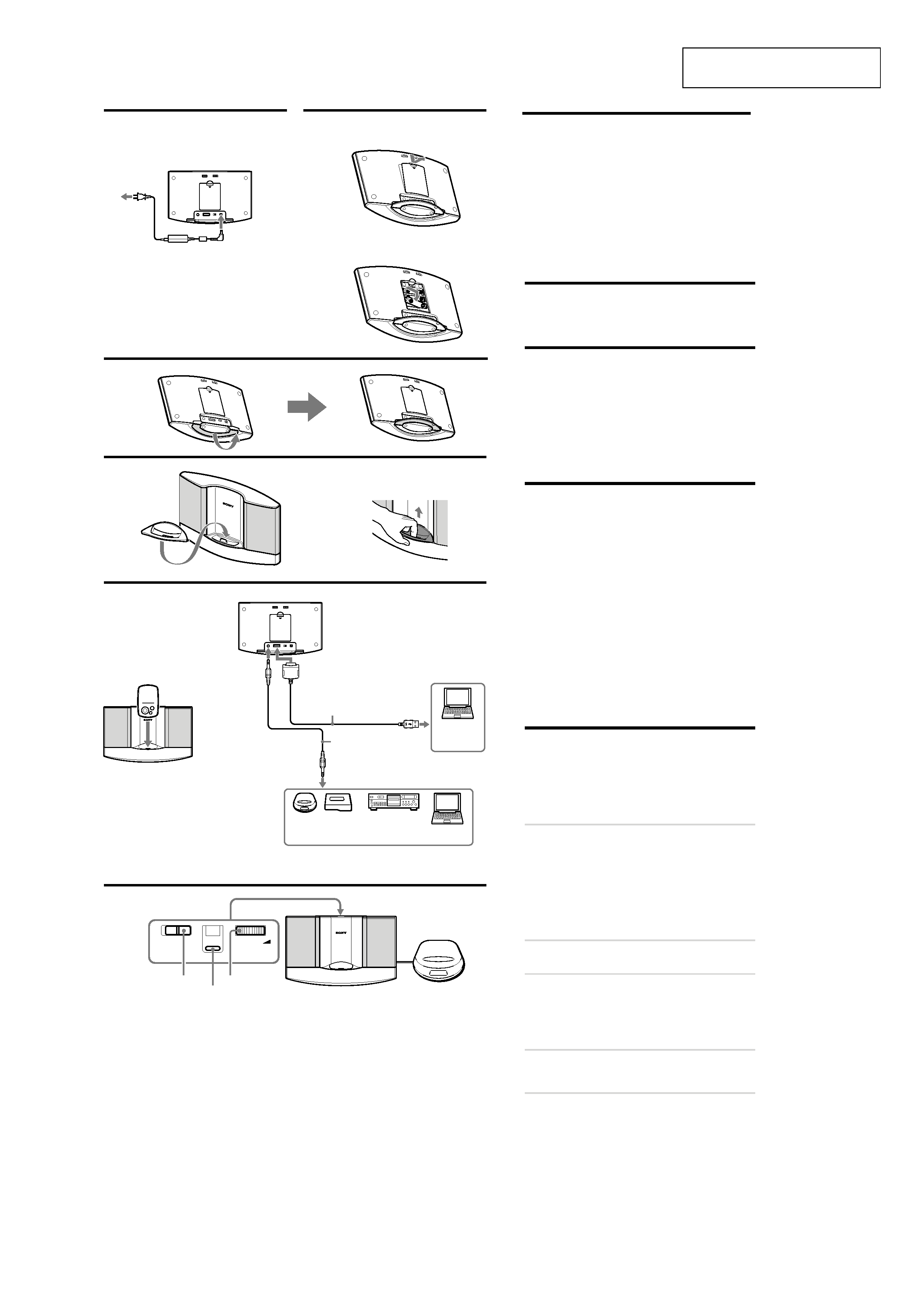
Power Sources
Using on house current
(See fig.
A)
When the AC power adaptor is connected to the system,
internal batteries are automatically disconnected.
Setting the stand
(See fig.
C)
Retract into the stand when carrying the speaker.
Installing/Removing the
attachment
(See fig.
D)
Installing the attachment according to the Walkman
you are using
Use the dedicated attachment for either NW-A1000 or
NW-A3000 series. The corresponding model number is
marked on the rear of the attachment. Exchange attachments,
as shown.
Hooking up the speaker
(See fig.
E)
Connect the speaker to the source equipment.
When the system is connected to the monaural jack
of a radio, etc., the sound may not come through the right
speaker. In such a case, use the optional* plug adaptor PC-
234S or PC-236MS.
To connect to a stereo phone-type
headphones jack
Use the optional* plug adaptor PC-234S/PC236MS or
connecting cord RK-G136/RK-G138.
* The above optional accessories are not provided in some areas.
Notes
·NW-A1000/A3000 series use the multiple connector (Walkman
connection).
· Do not carry the speaker with a Walkman set on the multiple
connector, as malfunction may result.
Playing back sound of the
connected device
(See fig.
F)
Adjust VOLUME to minimum to avoid any sudden loud
sounds that may hurt your ears and set the volume of the
connected device to a moderate level.
1
Disconnect the USB cable used for the
speaker and personal computer, or set
the POWER switch of the connected
personal computer to OFF.
· When a USB cable is connected between the speaker
and a personal computer, no sound will be heard from
a Walkman set on the multiple connector, as data
transfer mode takes place. Sound from the device
connected to INPUT will be heard instead.
2
Set the POWER switch to ON.
The POWER/CHARGE indicator lights up.
3
Play back the connected device.
Adjust VOLUME accordingly.
· When both a Walkman set on the multiple connector
and a device connected to INPUT are used, both
sounds can be heard. Control on/off on the connected
device itself.
4
Set the POWER switch to OFF after
using.
The POWER/CHARGE indicator goes off.
Notes
· If connecting the speaker to a device with built-in a radio or
tuner, radio reception may not occur or sensitivity may be
reduced significantly.
· Release the bass boost function of the connected Walkman, etc.,
to avoid distortion.
· The USB cable connecting the speaker with personal computer
is used for transferring Walkman's data and recharging. When
playing back sound of a personal computer using the speaker,
connect through the INPUT.
· If the connected device's headphone output has a line switch,
better sound will be heard if it is set to on. See the operating
instructions of the connected device.
Battery installation (See fig. B)
Battery replacement
When the batteries are weak, the POWER/CHARGE
indicator will start flickering and become faint, or the
playback sound will become distorted or unstable. In such a
case, replace all the batteries with new ones.
SRS-NWM10
4
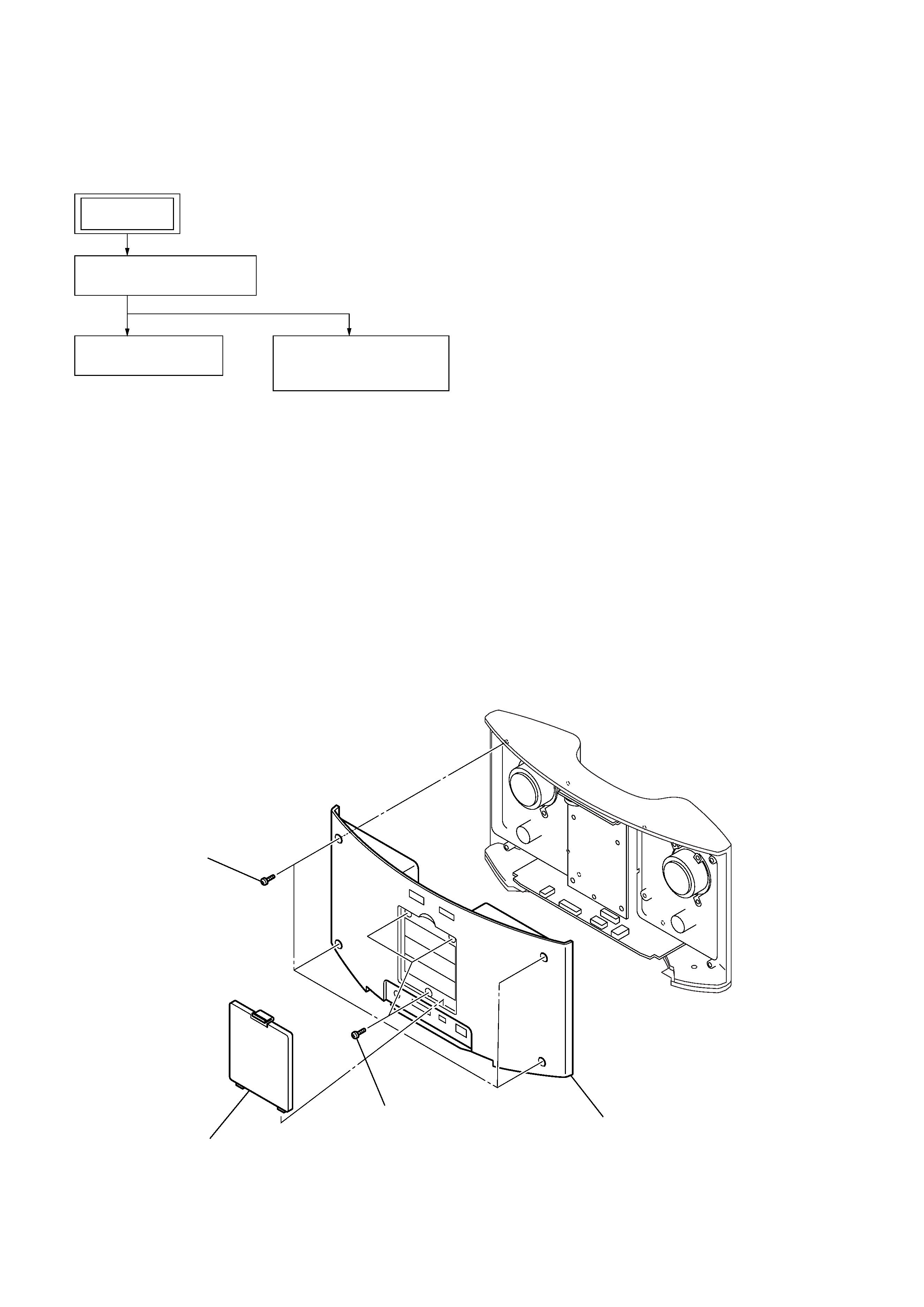
Note: Follow the disassembly procedure in the numerical order given.
2-2. REAR CABINET ASSY
· This set can be disassembled in the order shown below.
2-1. DISASSEMBLY FLOW
SECTION 2
DISASSEMBLY
3
four screws (B2.6)
2
three screws (B2.6)
4
rear cabinet assy
1
battery cover
2-2. REAR CABINET ASSY
(Page 4)
2-3. POWER BOARD
(Page 5)
2-4. AMPLIFIRER BOARD,
CONTROL BOARD
(Page 5)
SET
SRS-NWM10
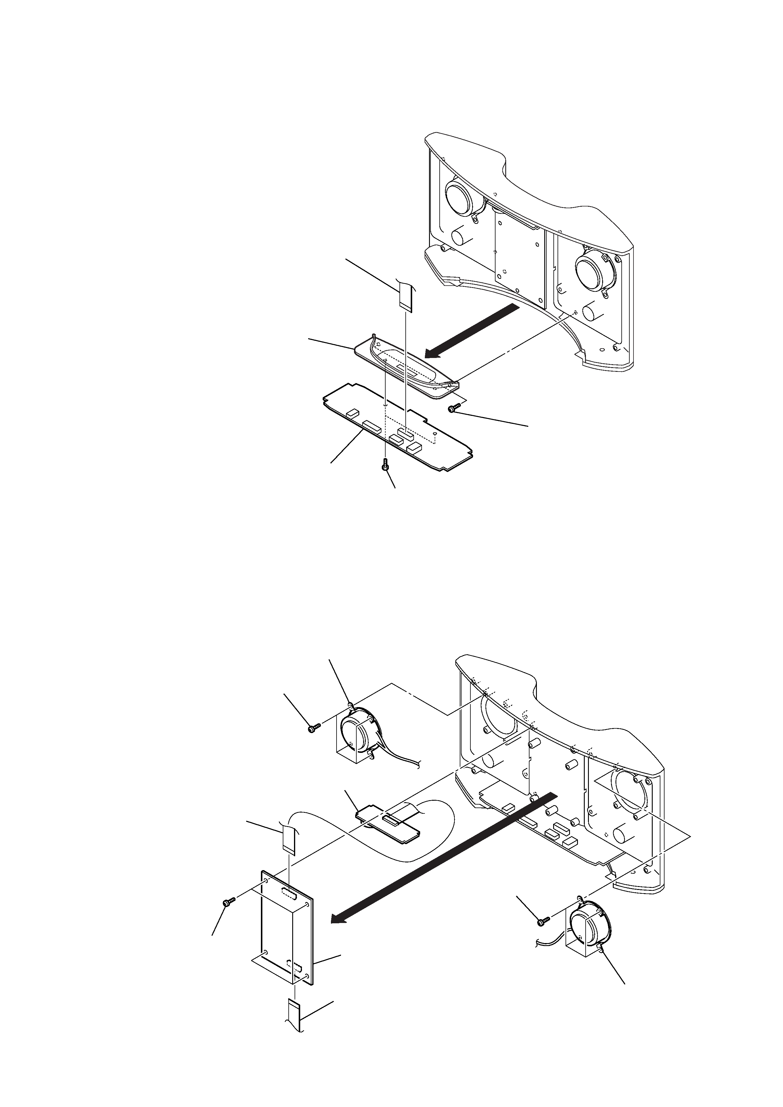
5
2-3. POWER BOARD
2-4. AMPLIFIRER BOARD, CONTROL BOARD
1
two screws (B2.6)
3
wire (flat type) (13 core)
(CN903)
5
connector panel
6
POWER board
4
two screws (B2.6)
2
3
speaker (R-ch) (SPK201)
5
speaker (L-ch) (SPK101)
2
four screws (B2.6)
0
CONTROL board
8
wire (flat type) (13 core)
(CN501)
7
wire (flat type) (13 core)
(CN502)
9
AMPLIFIER board
1
four screws (B2.6)
4
four screws (B2.6)
6