SRS-D4100/D5100
US Model
AEP Model
SRS-D4100/D5100
Canadian Model
UK Model
Korean Model
SRS-D5100
SERVICE MANUAL
ACTIVE SPEAKER SYSTEM
Sony Corporation
Parsonal Audio Company
Published by Sony Engineering Corporation
9-877-701-02
2004E02-1
© 2004.05
SPECIFICATIONS
Ver 1.1 2004. 05
Subwoofer
Satellite
Speaker
Control Box
Photo : SRS-D5100
Speaker section
Satellite speaker
Speaker system
Full range, magnetically shielded
Speaker units
5.6 cm, cone type
Enclosure type
Closed type
Impedance
6
Cord length
3 m
Subwoofer
Speaker system
Woofer
Speaker units
16 cm, cone type
Enclosure type
Bass reflex
Impedance
6
Amplifier section
Rated output
12 W (10% T.H.D., 1 kHz, 6
)
(Satellite speaker)
80 W (10% T.H.D., 100 Hz, 6
)
(Subwoofer)
Input
Stereo mini jack x 3
(INPUT 1 for 5.1 channel signal input)
(D5100)
Stereo mini jack x 2
(INPUT 1 for 4 channel signal input)
(D4100)
Stereo mini jack x 1
(INPUT 2 for 2 channel signal input)
Input impedance
4.7 k
(at 1 kHz)
Output
Stereo mini jack x1 (PHONES)
General
Dimensions (w/h/d)
Approx. 166 x 40 x 83 mm
(6 5/
8 x 1
5/
8 x 3
3/
8 in.) (Control box)
Approx. 95 x 135 x 150 mm
(3 3/
4 x 5
3/
8 x 6 in.)
(Satellite speaker, on a desk)
Approx. 95 x 100 x180 mm
(3 3/
4 x 4 x 7
1/
8 in.)
(Satellite speaker, attached to a wall)
Approx. 285 x 285 x 462 mm
(11 1/
4 x 11
1/
4 x 18
1/
4 in.)(Subwoofer)
Mass
Approx. 240 g (8 oz.) (Control box)
Approx. 490 g (1 lb. 1 oz.)
(Satellite speaker)
Approx. 8.7 kg (19 lb. 3 oz.)(Subwoofer)
(D5100)
Approx. 8.6 kg (18 lb. 15 oz.)(Subwoofer)
(D4100)
Cord length
2 m (Control box to subwoofer)
2 m (Power cord)
Power consumptions
42 W (D5100)
41 W (D4100)
Power requirements
Where purchased
Operating voltage
US, Canadian model
120 V AC, 60 Hz
AEP, UK, Korean model
220 230 V AC, 50 Hz
Supplied accessories
Connecting Cable (for 5.1 channel signal input) (D5100)
Connecting Cable (for 4 channel signal input) (D4100)
Design and specifications are subject to change without notice.
2
SRS-D4100/D5100
TABLE OF CONTENTS
Specifications ............................................................................ 1
1.
GENERAL ................................................................... 3
2.
DIAGRAMS
2-1.
Schematic Diagram Amp Section ............................... 5
2-2.
Printed Wiring Boards Amp Section (Side A) ............. 6
2-3.
Printed Wiring Boards Amp Section (Side B) ............. 7
2-4.
Printed Wiring Boards Control Section (D5100) ....... 8
2-5.
Printed Wiring Boards Control Section (D4100) ....... 9
2-6.
Schematic Diagram Control Section .......................... 10
3.
EXPLODED VIEWS
3-1.
Subwoofer Section .......................................................... 11
3-2.
Control Box, Satellite Speaker Section ........................... 12
4.
ELECTRICAL PARTS LIST .................................. 13
SAFETY CHECK-OUT
After correcting the original service problem, perform the following
safety checks before releasing the set to the customer:
Check the antenna terminals, metal trim, "metallized" knobs, screws,
and all other exposed metal parts for AC leakage. Check leakage as
described below.
LEAKAGE
The AC leakage from any exposed metal part to earth Ground and
from all exposed metal parts to any exposed metal part having a
return to chassis, must not exceed 0.5 mA (500 microampers).
Leakage current can be measured by any one of three methods.
1. A commercial leakage tester, such as the Simpson 229 or RCA
WT-540A. Follow the manufacturers' instructions to use these
instruments.
2. A battery-operated AC milliammeter. The Data Precision 245
digital multimeter is suitable for this job.
3. Measuring the voltage drop across a resistor by means of a
VOM or battery-operated AC voltmeter. The "limit" indication
is 0.75 V, so analog meters must have an accurate low-voltage
scale. The Simpson 250 and Sanwa SH-63Trd are examples
of a passive VOM that is suitable. Nearly all battery operated
digital multimeters that have a 2V AC range are suitable. (See
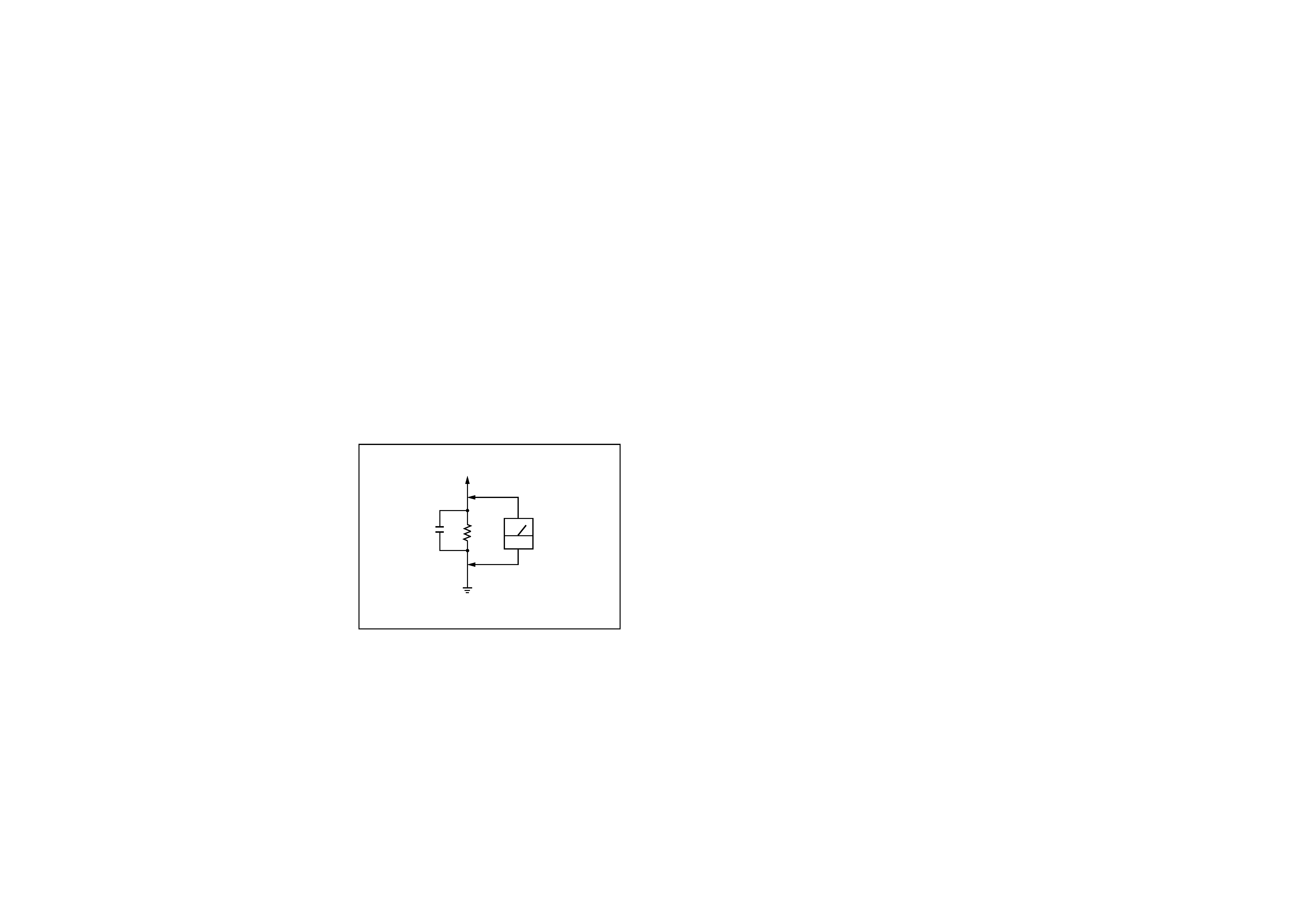
Fig. A)
Fig. A. Using an AC voltmeter to check AC leakage.
0.15
µF
To Exposed Metal
Parts on Set
1.5k
AC
voltmeter
(0.75V)
Earth Ground
SAFETY-RELATED COMPONENT WARNING!!
COMPONENTS IDENTIFIED BY MARK 0 OR DOTTED LINE
WITH MARK 0 ON THE SCHEMATIC DIAGRAMS AND IN THE
PARTS LIST ARE CRITICAL TO SAFE OPERATION. REPLACE
THESE COMPONENTS WITH SONY PARTS WHOSE PART
NUMBERS APPEAR AS SHOWN IN THIS MANUAL OR IN
SUPPLEMENTS PUBLISHED BY SONY.
ATTENTION AU COMPOSANT AYANT RAPPORT
À LA SÉCURITÉ!!
LES COMPOSANTS IDENTIFIÉS PAR UNE MARQUE 0 SUR LES
DIAGRAMMES SCHÉMATIQUES ET LA LISTE DES PIÈCES
SONT CRITIQUES POUR LA SÉCURITÉ DE FONCTIONNEMENT.
NE REMPLACER CES COMPOSANTS QUE PAR DES PIÈCES
SONY DONT LES NUMÉROS SONT DONNÉS DANS CE MANUEL
OU DANS LES SUPPLÉMENTS PUBLIÉS PAR SONY.
3
SRS-D4100/D5100
SECTION 1
GENERAL
This section is extracted
from instruction manual.
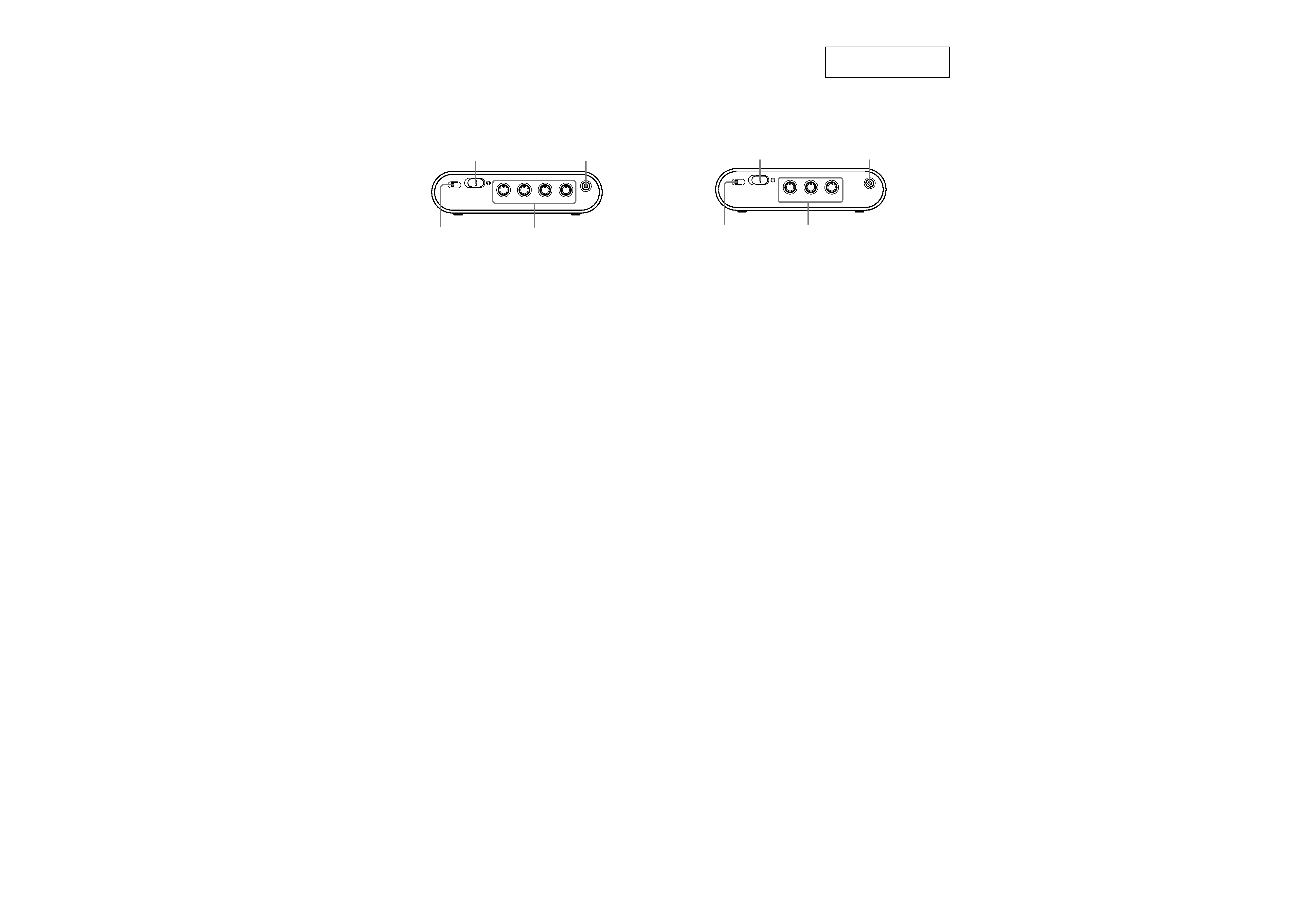
LOCATING THE CONTROLS
VOLUME
BASS
REAR
CENTER
PHONE
ON
OFF
POWER
ON
OFF
Dual Stereo
MIN
MAX
POWER
VOLUME
PHONES
DUAL STEREO
Control box
VOLUME
BASS
REAR
PHONE
ON
OFF
POWER
ON
OFF
DUAL STEREO
MIN
MAX
POWER
VOLUME
PHONES
DUAL STEREO
Control box
D5100
D4100

4
SRS-D4100/D5100
SECTION 2
DIAGRAMS
For schematic diagrams.
Note:
· All capacitors are in
µF unless otherwise noted. pF: µµF 50 WV or
less are not indicated except for electrolytics and tantalums.
· All resistors are in
and 1/4 W or less unless otherwise specified.
· C : panel designation.
· A : B+ Line.
· B : B Line.
·Voltages are dc with respect to ground under no-signal conditions.
· no mark : Power on
·Voltages are taken with a VOM (Input impedance 10 M
).
Voltage variations may be noted due to normal production toler-
ances.
· Signal path.
F
: AUDIO
· Abbreviation
CND : Canadian model
KR
: Korean model
THIS NOTE IS COMMON FOR PRINTED WIRING BOARDS AND SCHEMATIC DIAGRAMS.
(In addition to this necessary note is printed in each block.)
Note:
The components identi-
fied by mark 0 or dotted
line with mark 0 are criti-
cal for safety.
Replace only with part
number specified.
Note:
Les composants identifiés par
une marque 0 sont critiques
pour la sécurité.
Ne les remplacer que par une
piéce portant le numéro
spécifié.
For printed wiring boards.
Note:
· X : parts extracted from the component side.
·
: Pattern from the side which enables seeing.
· Abbreviation
CND : Canadian model
KR
: Korean model
Ver 1.1
SRS-D4100/D5100
5
5
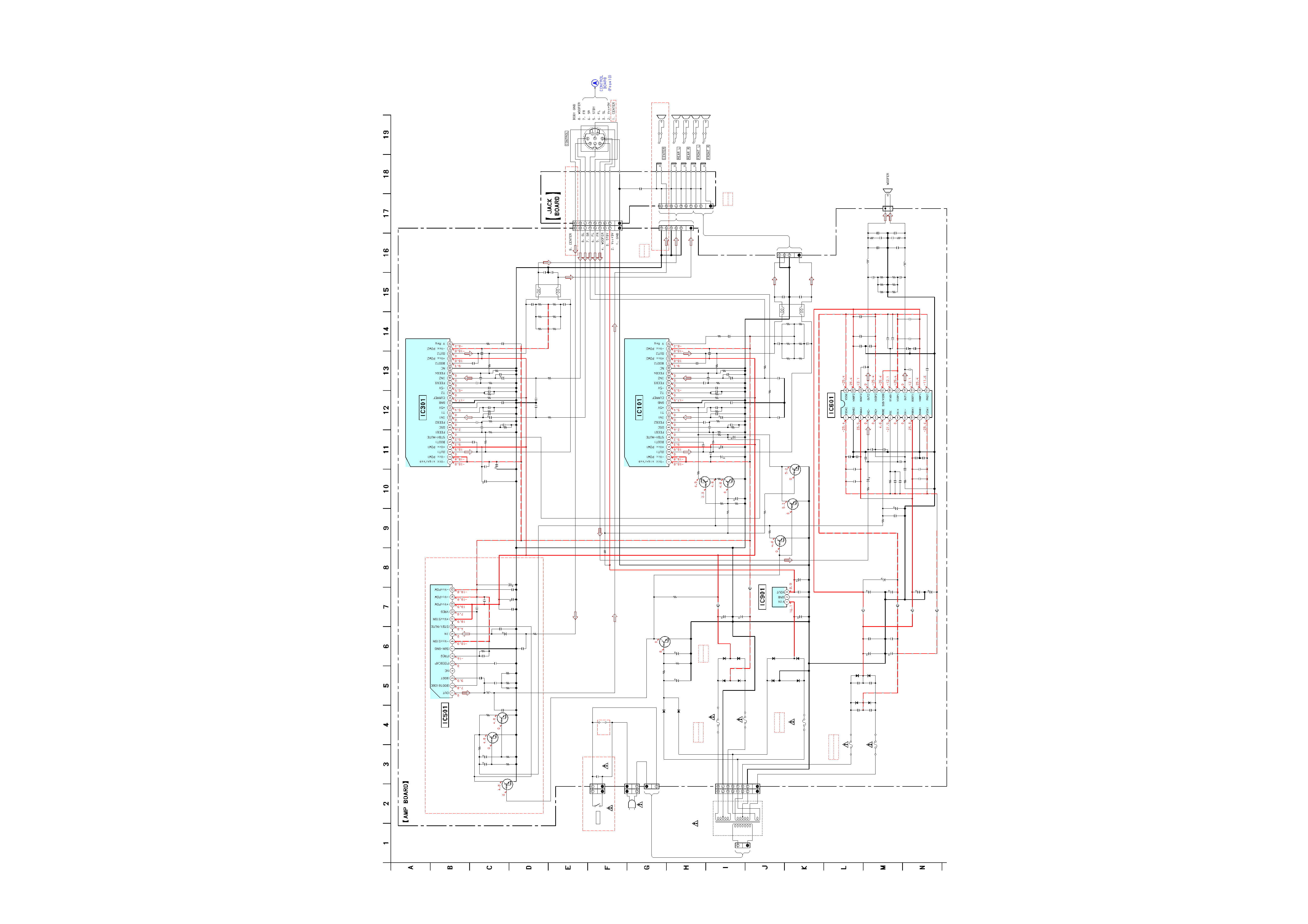
2-1. SCHEMATIC DIAGRAM AMP SECTION
C903
C904
C901
C902
R625
R624
R626
R627
R523
R522
R360
R353
R355
R354
R356
R357 R358
R359
R362
R361
R351
R427
C905
R160
C152
C151
R153
R155
R154
R156
R157 R158
R159
R162
R161
R151
R125
R226
C155
R152
FB601
FB602
FB603
FB604
CNP903
R57
R56
R59
R55
C54
C55
R60
R61
R62
R63
R524
D51
D52
R51
R52
R53
R64
R126
R127
R225
R227
R325
R326
R327
R425
R426
R630
R631
R632
R633
R581
R481
R381
R281
C56
R65
CNP901
CN901
CN903
C58
C59
FB101
R623
C638
C632
R622
R621
C666
C667
C910
C663
C664
IC301
C357
C360
C362
IC101
C157
C160
C162
C127
CNP904
CN904
CN601
CN101
C621
C225
C125
C425
C325
C51
R629
C53
C642
C126
C226
C326
C426
C906
CN902
T901
L501
60
µH
L602
33
µH
33
µH
L601
L101
33
µH
L301
33
µH
C647
C646
C648
C649
C651
C650
C644
C645
C639
C634
C640
C629
C628
C627
C625
C624
C622
C652
C661
C662
C964
C961
C963
C962
C356
C358
C359
C361
C364
C363
C365
C369
C327
C328
C428
C427
C165
C169
C164
C161
C163
C159
C158
C156
C154
C153
C281
C181
C128
C228
C522
C521
C523
C524
C581
C528
C529
C52
JW901
C909
Q58
Q59
Q51
Q57
Q53
Q54
Q55
Q56
C534
R521
IC501
C481 C381
R181
IC601
IC901
R66
C533
C526
C525
J105
C530
C531
C532
FH901
FH902
FH903
FH904
FH910
FH909
F902
F903
F904
FH906
FH905
FH907
FH908
D901
D902
D903
D904
D909
D910
D911
D912
D905
D906
D907
D908
C653
C623
C626
C654
C655
C631
C637
C657
C635
C656
C641 C658
C633
C57
CNP101
CN102
CNP1
C166
C366
R54
CNP102
FB102
F905
C643
C630
C227
C354
C353
C352
C351
F901
Q52
J110
J108
J107
J106
J109
S901
6800
35V
6800
35V
6800
35V
6800
35V
15
1/10W
15
1/10W
22
1W
22
1W
470
1/10W
12k
4.7k
4.7k
68k
10k
22k
130k 22k
68k
6.8
51k
51k
330
1/10W
1000
25V
4.7k
470
35V
470
35V
4.7k
68k
10k
22k
130k 22k
68k
6.8
51k
51k
330
1/10W
330
1/10W
10
50V
30k
0UH
0UH
0UH
0UH
2P
47k
4.7k
100
4.7k
4.7
50V
10
50V
47k
47k
12k
10k
470
1/10W
1SS355TE-17
1SS355TE-17
47k
47k
4.7k
100
330
1/10W
330
1/10W
330
1/10W
330
1/10W
330
1/10W
330
1/10W
330
1/10W
330
1/10W
330
1/10W
15
1/10W
15
1/10W
15
1/10W
15
1/10W
4.7k
4.7k
4.7k
4.7k
22
16V
2.2k
2P
2P
2P
2200p
2200p
0UH
5.6k
0.015
0.015
30k
5.6k
47
35V
47
35V
47
16V
470
35V
470
35V
TDA7490L
24p
0.1
0.1
TDA7490L
24p
0.1
0.1
560p 50V CH
8P
8P
2P
9P
0.47
50V
0.33
50V
0.33
50V
0.33
50V
0.33
50V
0.1
50V
100
100
10V
47
63V
1000p
1000p
1000p
1000p
2200p/250V
0.68
0.68
0.22
0.22
0.015
0.015
560p
560p
0.1
0.1
0.1
0.1
0.47
330p
330p
0.1
0.1
0.01
0.1
0.1
0.047
0.047
0.047
0.047
470p
470p
330p
330p
470p
470p
0.033
0.1
560p
0.68
0.68
560p
0.033
0.1
470p
330p
470p
330p
470p
470p
0.033
0.1
0.001
0.001
0.68
0.68
0.1
560p
0.0047
270p
0.001
0.1
0.1
0.01
DTC144EUA
MUTE
DTC144EUA
MUTE
DTC144EUA
AC DETECT
DTC144EUA
MUTE
SWITCH
DTC144EUA
MUTE
DTC144EUA
MUTE
DTA144EUA
MUTE
DTC144EUA
MUTE
0.68
470
1/10W
TDA7481
0.001 0.001
4.7k
TDA8921TH
KIA78S09
1k
470
35V
0.001
0.33
50V
8P
0.1
470
35V
0.1
U15G
U15G
U15G
U15G
10E2
10E2
10E2
10E2
U15G
U15G
U15G
U15G
0.1
100V
0.1
100V
0.1100V
0.1100V
0.1
100V
0.1
100V
0.1 100V
0.1 100V
0.1
100V
0.1
100V
0.1
100V
0.1
100V
0.1
100p
9P
0.1
100V
0.1
100V
10k
4P
0UH
47p
0.1
560p
0.033
0.1
470
35V
470
35V
DTC144EUA
MUTE
DRIVE
*
*2
*3
*3
*3
*2
*4
*2
AEP,UK,KR
US,CND
0.1/50V
1/50V
AEP,UK,KR
US,CND
D5100
T901
POWER
TRANSFORMER
SATELLITE
AMP
POWER
+9V REG.
AMP
POWER
AMP
POWER
AMP
POWER
*1 C52
AEP,UK,KR
US,CND
*2 F901,902
5A/125V
T5AL/250V
AEP,UK,KR
US,CND
AEP,UK,KR
US,CND
*4 F905
1A/125V
T1AL/250V
*3 F903,904
6.3A/125V
T6.3AL/250V
D5100
D4100
D5100
SPEAKERS
D4100
D5100
4P
6P
8P
10P
D5100
*2 CNP103
*3 CN102
D5100
AC IN
POWER
Ver 1.1