SRS-A57
SERVICE MANUAL
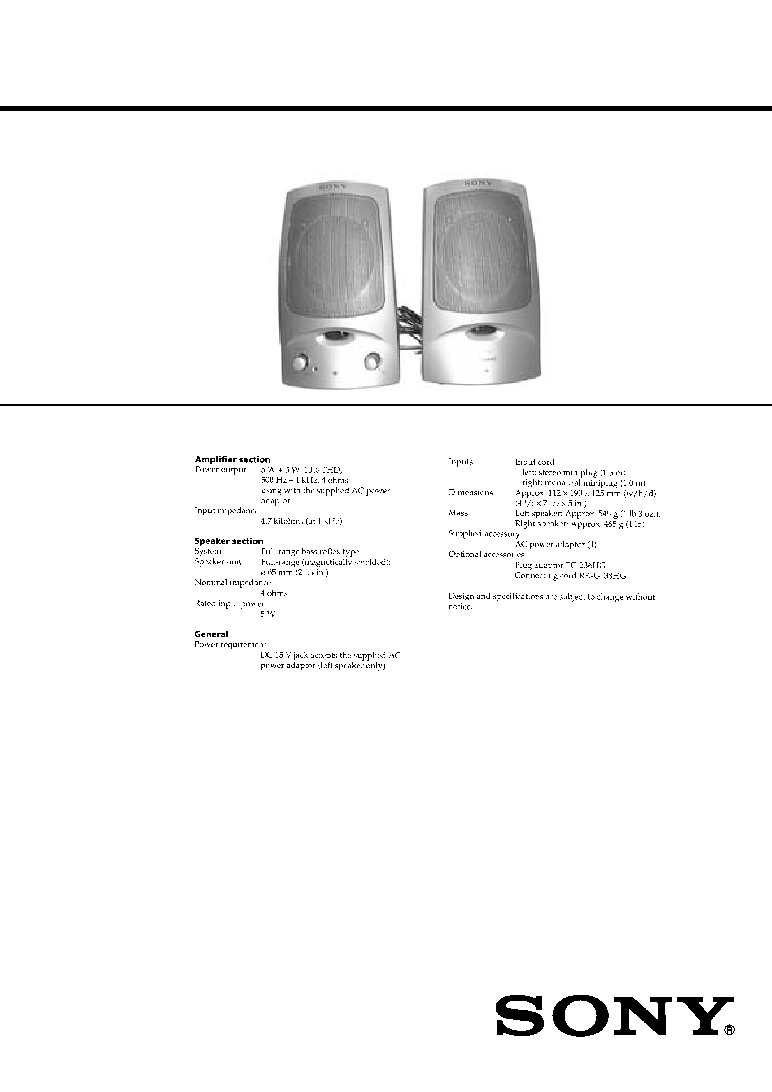
ACTIVE SPEAKER SYSTEM
SPECIFICATIONS
US Model
Canadian Model
AEP Model
UK Model
Australian Model
E Model
Sony Corporation
Personal Audio Company
Shinagawa Tec Service Manual Production Group
9-927-655-12
2001G0200-1
© 2001.7
Ver 1.1 2001.07
2
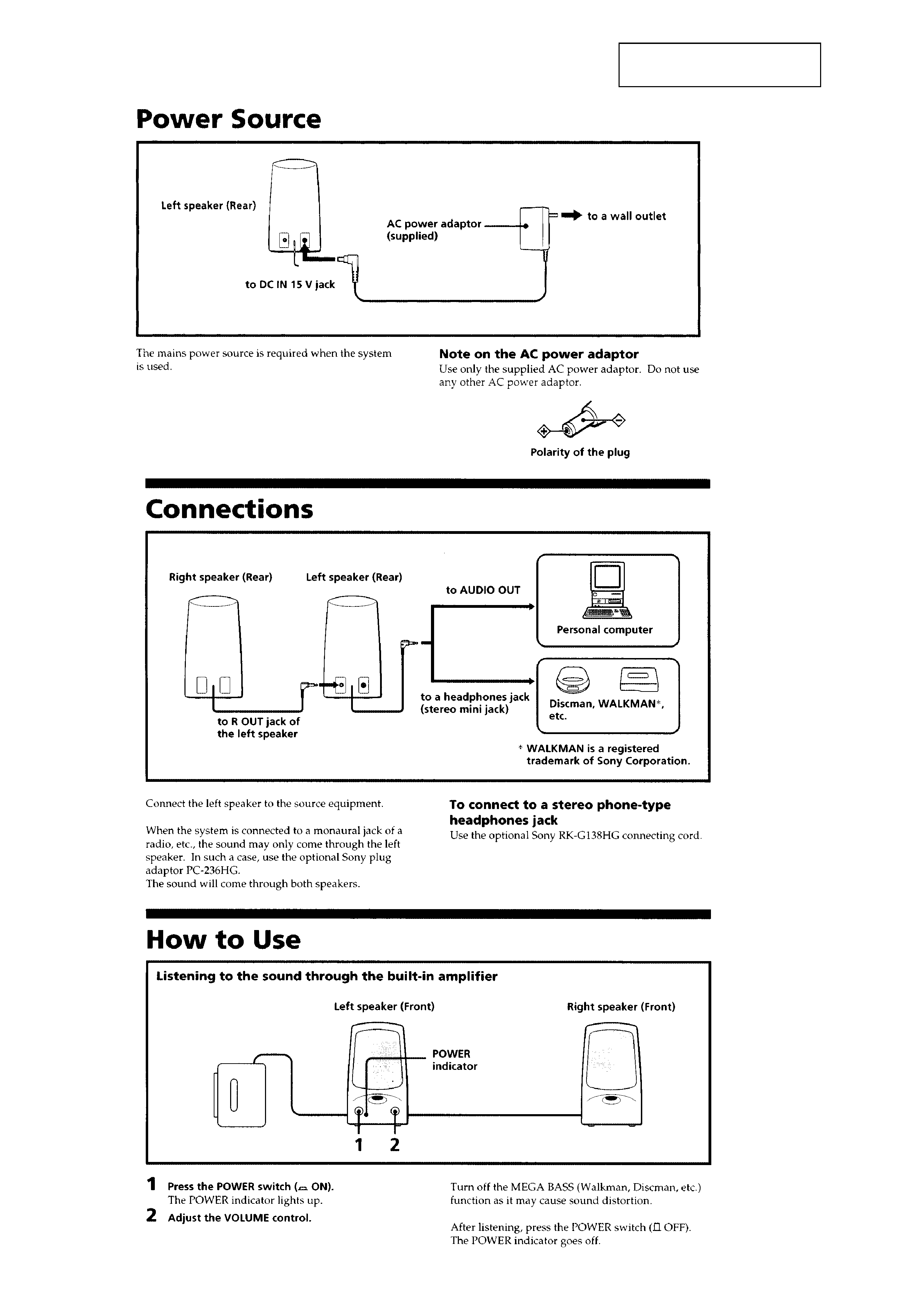
SECTION 1
GENERAL
This section is extracted from
instruction manual.
SRS-A57
SECTION 2
DIAGRAMS
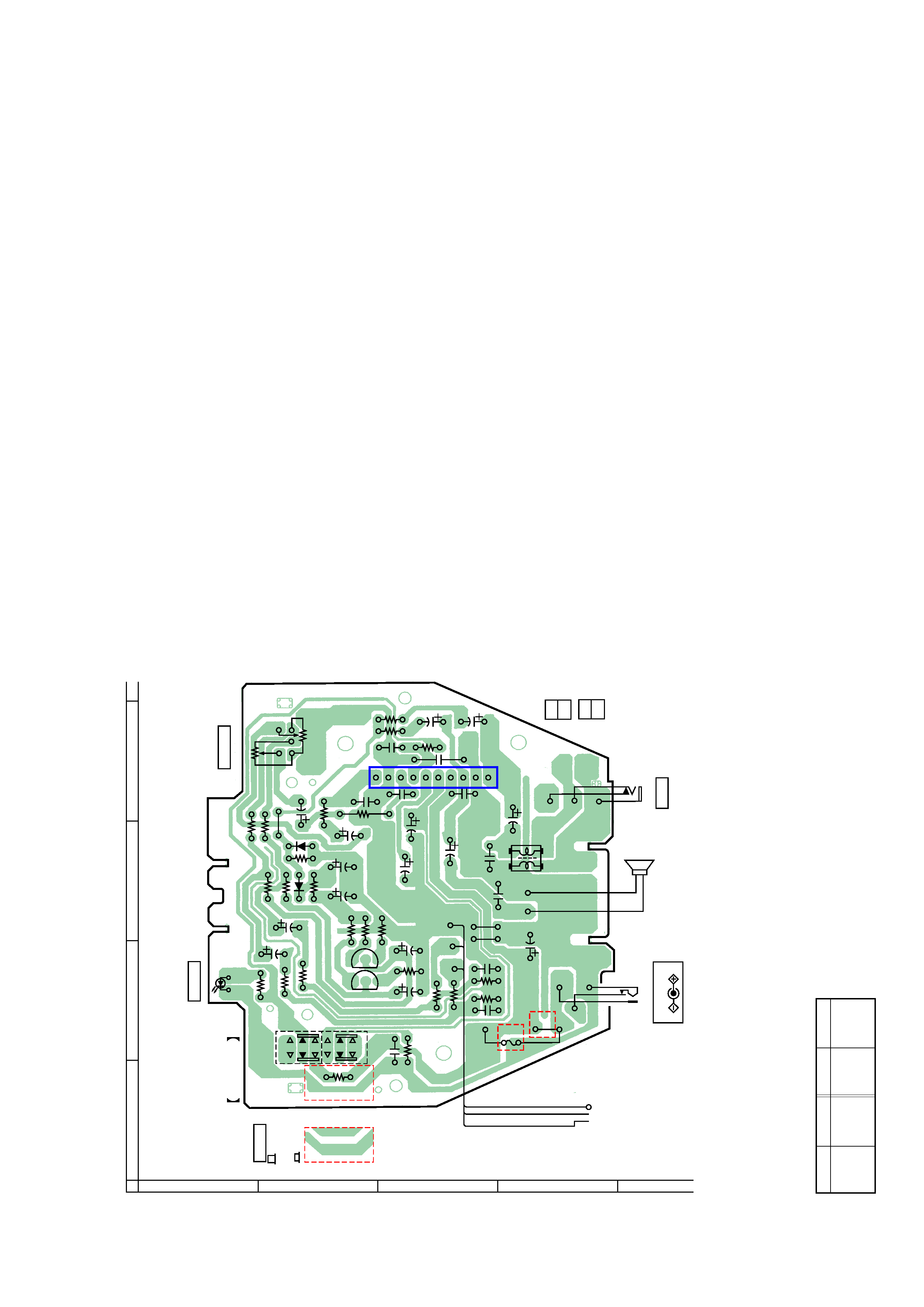
2-1. PRINTED WIRING BOARDS
3
4
Note:
· X : parts extracted from the component side.
· b : Pattern on the side which is seen.
D1
B-3
D2
B-3
D4
A-2
Ref. No.
Location
z
Semiconductor Location
Ref. No.
Location
IC1
C-4
Q1
B-2
Q2
B-2
2
3
4
A
1
B
C
D
E
12
(12)
1-675-921-
11
(11)
SW1
-1
-2
SW1
POWER
OFF
R
ON
D4
POWER
D4
R16
R23
R14
R24
R4
R3
R20
R5
R6
R9
R7
R8
R10
R15
R22
R12
R11
R13
R2
R1
R21
JW4
C1
C2
C7
C4
C3
C8
C5
C6
D1
D2
B
C
E
Q2
B
C
E
Q1
C25
C13
C12
C15
C16
C19
C20
C21
C18
C17
C26
C27
R19
R18
R17
C10
C9
C22
C23
10
1
5
IC1
RV1
VOLUME
RV1-2
RV1-1
JW1
JW6
JW2
C11
FU1
US MODEL
EXCEPT
US MODEL
DC IN 15V
JK1
L1
JK2
R OUT
SP1
SPEAKER
(L-CH)
+
+
RED
WHT
RED
WHT
BLK
P1
(INPUT)
RH BOARD
Last digit: -12
Last digit: -11
Ver 1.1 2001.07
SRS-A57
Ver 1.1 2001.07
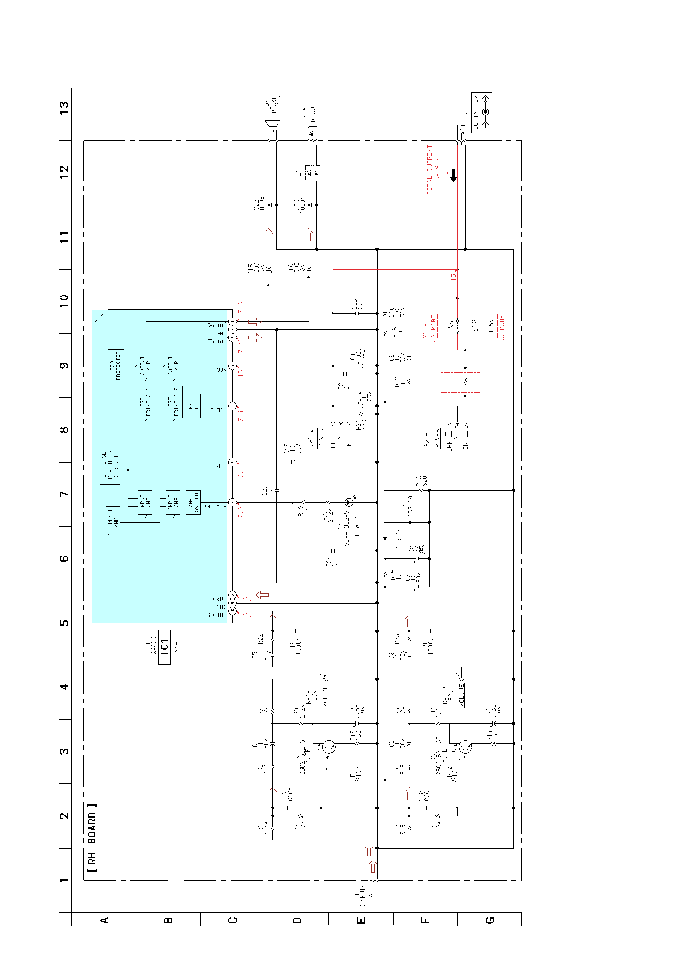
2-2. SCHEMATIC DIAGRAM
6
5
Note:
· All capacitors are in F unless otherwise noted. pF:
F
50 WV or less are not indicated except for electrolytics
and tantalums.
· All resistors are in
and 1/4 W or less unless otherwise
specified.
·
: B+ Line.
· Power voltage is dc 15V and fed with regulated dc power
supply from external power voltage jack.
· Voltages are dc with respect to ground under no-signal
conditions.
· Voltages are taken with a VOM (Input impedance 10 M ).
Voltage variations may be noted due to normal produc-
tion tolerances.
· Signal path.
R24
1k
2.5A
Last digit: -12
Last digit: -11
7
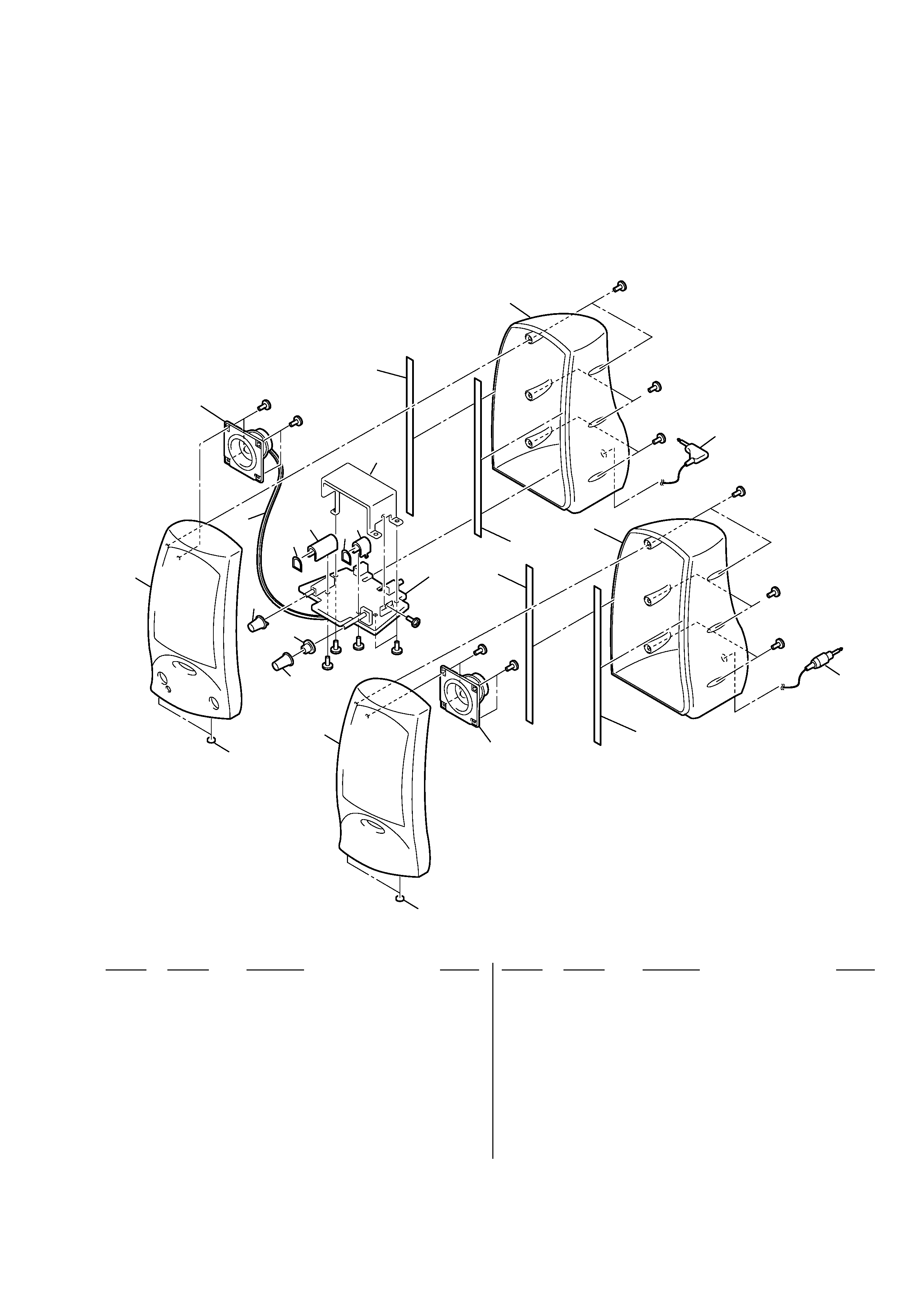
SECTION 3
EXPLODED VIEW
NOTE :
· -XX, -X mean standardized parts, so they
may have some difference from the original
one.
· Items marked " * "are not stocked since they
are seldom required for routine service. Some
delay should be anticipated when ordering
these items.
· The mechanical parts with no reference
number in the exploded views are not
supplied.
· Hardware (# mark) list and accessories and
packing materials are given in the last of this
parts list.
Ref. No.
Part No.
Description
Remark
Ref. No.
Part No.
Description
Remark
1
4-225-536-01 FOOT,RUBBER
2
X-3378-878-1 CABINET (R) ASSY, FRONT
3
X-3378-877-1 CABINET (L) ASSY, FRONT
4
4-224-723-01 SPACER
5
4-224-721-01 KNOB(VOL)
6
4-224-722-01 KNOB(POWER)
7
3-045-507-01 CUSHION (A)
8
4-226-147-01 HOLDER, POWER
9
4-226-146-01 HOLDER, VOLUME
* 10
A-4541-197-A RH BOARD, COMPLETE (US)
* 10
A-4541-200-A RH BOARD, COMPLETE (EXCEPT US)
11
3-045-508-01 CUSHION (B)
12
4-224-718-01 CABINET (L), REAR
13
1-791-865-11 CORD(WITH PLUG) (INPUT)
14
4-224-719-01 CABINET (R), REAR
15
1-791-864-11 CORD(WITH PLUG) (R-CH SPEAKER INPUT)
16
1-792-607-11 CORD, SPEAKER
SP1
1-529-542-11 SPEAKER (L-CH)
SP2
1-529-542-11 SPEAKER (R-CH)
not supplied
#1
#1
#2
#2
#2
#3
#3
#3
#3
#3
#3
#2
#2
#2
#2
1
3
1
2
6
5
10
11
11
14
11
11
12
13
15
4
9
7
7
8
16
SP1
SP2