Ver 1.0 1999.10
MICROFILM
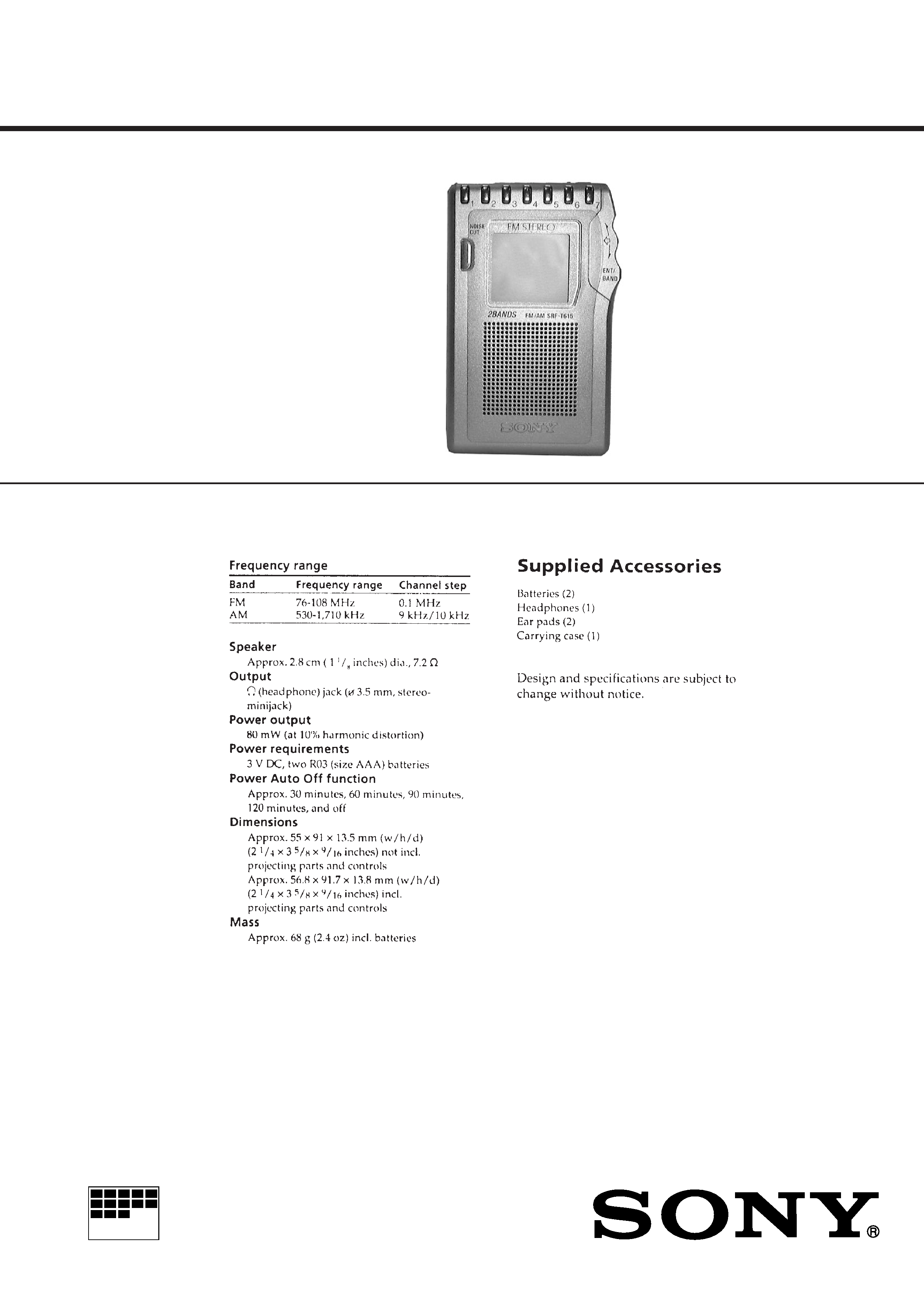
SRF-T615
SERVICE MANUAL
FM STEREO/AM PLL SYNTHESIZED RADIO
SPECIFICATIONS
Tourist Model
2
Specifications ........................................................................... 1
1. GENERAL
Location and Function of Controls .................................... 2
2. DISASSEMBLY
2-1. Cover (JOG) (A) ......................................................... 3
2-2. Lid, Battery Case ........................................................ 3
2-3. Cabinet (Rear) ............................................................. 4
2-4. Main Board ................................................................. 4
3. ADJUSTMENTS .......................................................... 5
4. DIAGRAMS
4-1. Explanation of IC Terminals ....................................... 7
4-2. Block Diagrams .......................................................... 9
4-3. Printed Wiring Boards .............................................. 12
4-4. Schematic Diagram ................................................... 15
5. EXPLODED VIEW ..................................................... 19
6. ELECTRICAL PARTS LIST .................................... 20
Flexible Circuit Board Repairing
· Keep the temperature of the soldering iron around 270°C during
repairing.
· Do not touch the soldering iron on the same conductor of the
circuit board (within 3 times).
· Be careful not to apply force on the conductor when soldering or
unsoldering.
Notes on chip component replacement
· Never reuse a disconnected chip component.
· Notice that the minus side of a tantalum capacitor may be dam-
aged by heat.
TABLE OF CONTENTS
SECTION 1
GENERAL
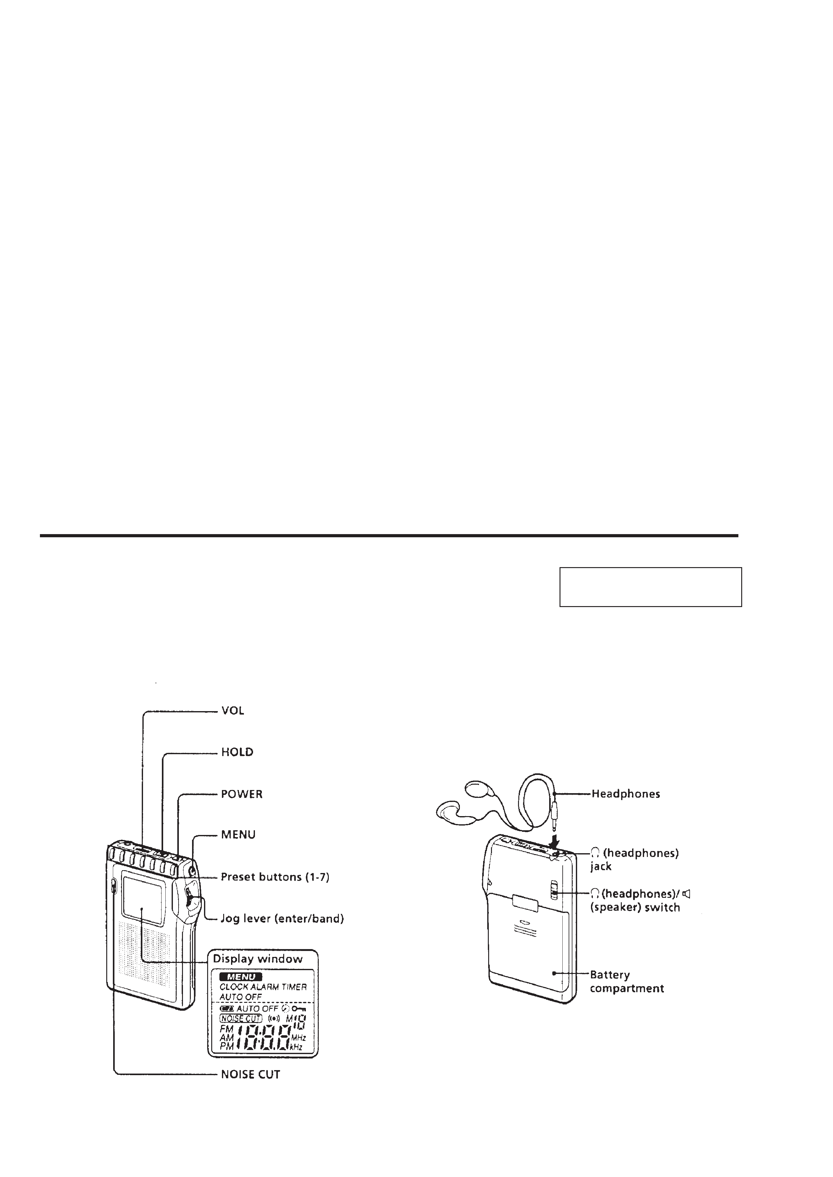
LOCATION AND FUNCTION OF CONTROLS
This section is extracted from
instruction manual.
3
SECTION 2
DISASSEMBLY
Note : Follow the disassembly procedure in the numerical order given.
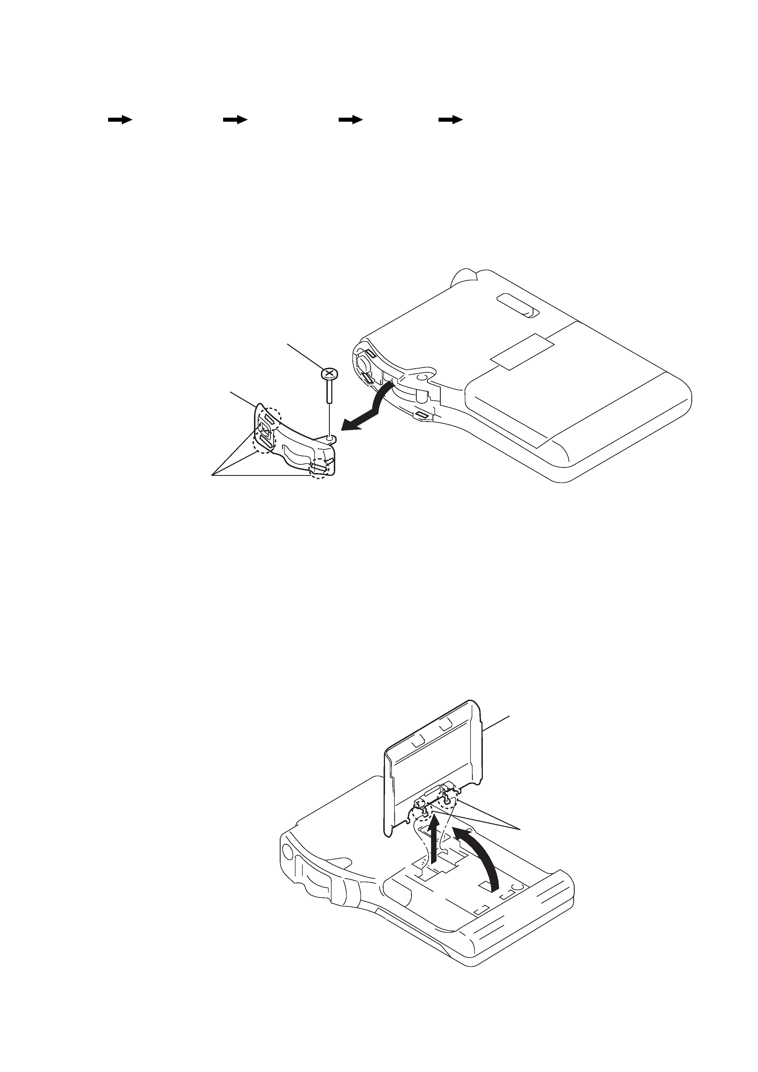
2-1. COVER (JOG) (A)
2-2. LID, BATTERY CASE
r
The equipment can be removed using the following procedure.
Cover (JOG) (A)
Set
Lid, Battery Case
Cabinet (Rear)
Main Board
1
Screw (B1.7x9)
2
Three claws
3
Turn from upper side
of the cover (JOG) (A),
and remove it.
Cover (JOG) (A)
3
Two claws
1
2
Lid, battery case
4
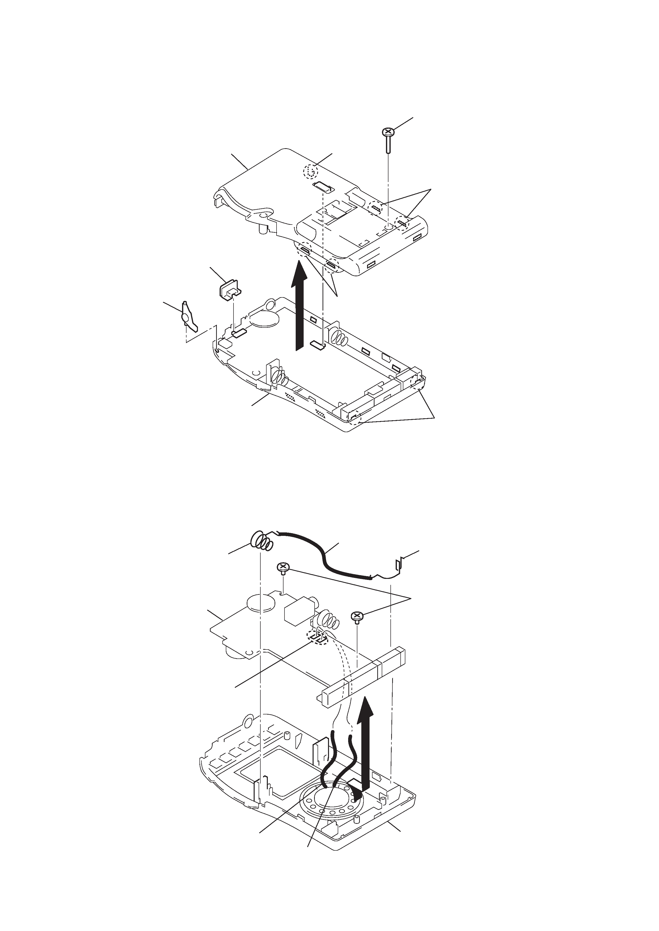
2-3. CABINET (REAR)
2-4. MAIN BOARD
1
Screw (1.7x9)
2
Two claws
2
Two claws
2
Two claws
3
2
Claw
5
Button (MENU)
4
Knod (HOLD)
Cabinet (front) ASSY
Cabinet (rear)
1
Lead wire (Black)
3
Remove solder
Main board
2
Screws (1.4)
4
Terminal (+) (A), battery
Terminal () (A), battery
Cabinet (front) ASSY
Black
Brown
5
TUNER SECTION
AM Section
Band : AM
Volume : MIN
FM Section
Band : FM
Volume : MIN
· Repeat the procedures in each adjustment several times, and the
frequency coverage and tracking adjustments should be finally
done by the trimmer capacitors.
AM IF ADJUSTMENT
Adjust for a maximum reading on level meter.
T101
450kHz
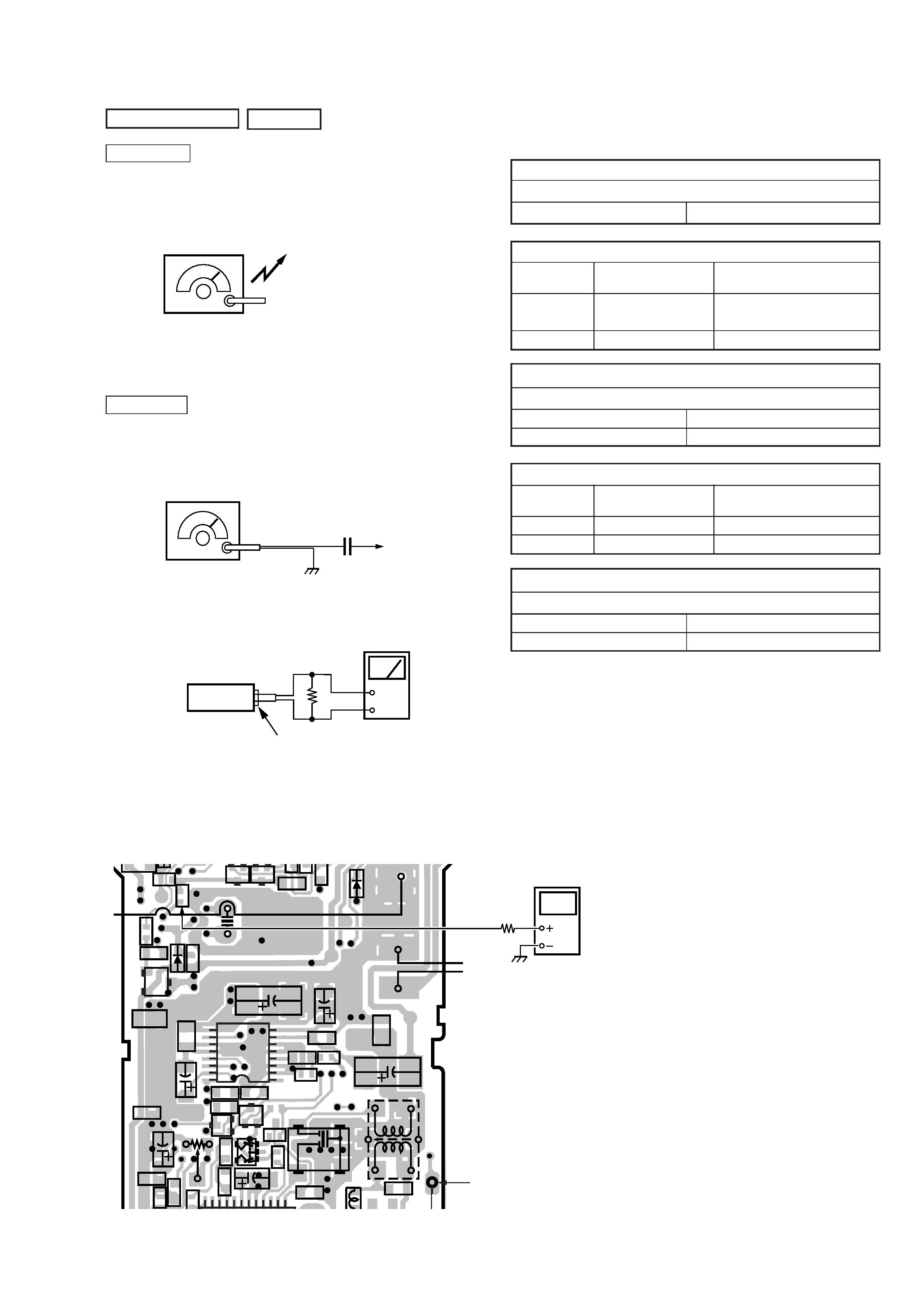
AM FREQUENCY COVERAGE ADJUSTMENT
Adjust part
Frequency display
reading on digital
voltmeter.
L103
531kHz
Adjustment Value : 2.5V
Standard Value : 2.45 2.55V
Confirmation
1,710kHz
7.8 10.8V
AM TRACKING ADJUSTMENT
Adjust for a maximum reading on level meter.
L104
585kHz
CT101
1,485kHz
FM FREQUENCY COVERAGE CONFIRMATION
Adjust part
Frequency display
reading on digital
voltmeter.
Confirmation
76.0MHz
2.2 4.2V
Confirmation
108.0MHz
7.5 10.5V
FM TRACKING ADJUSTMENT
Adjust for a maximum reading on level meter.
L101
76.0MHz
CT102
108.0MHz
SECTION 3
ADJUSTMENTS
AM RF signal
generator
30% amplitude modulation by 400Hz
signal.
Output level : as low as possible
Put the lead-wire
antenna close to
the set.
FM RF signal
generator
22.5kHz frequency deviation by
400Hz signal.
Output level : as low as possible
TP102 (RF IN)
MAIN board
0.01
µF
set
16
+
Headphone jack (J301)
level meter
0dB = 1
µ V
Frequency Coverage Adjustment
Connect Location :
R541
R603
R542
R533
C120
C608
D
C603
C605
X501
D501
D104
C311
C309
C310
C301
C314
Q201
CF102
13
15
20
24
T101
Q602
B
E
C
C127
C204
C131
C51
R119
R309
R310
R607
R201
R
116
R120
R
5
R
5
C124
C207
C313
C308
C307
C312
C201
C504
ECB
Q504
ECB
Q503
C17
BCE
BCE
Q202
C121
L
106
Q103
C206
1
5
8
9
12
16
IC301
RV201
-1
Digital
voltmeter
100k
TP102
(RF IN)
R533
[MAIN BOARD] (SIDE B)