
SRF-QT1
E Model
SERVICE MANUAL
FM STEREO RADIO
MICROFILM
SPECIFICATIONS
Frequency range:
FM 87.5 108 MHz
Output:
i
(headphones) jack
(ø 3.5 mm stereo minijack)
Power output:
1.5 mW + 1.5 mW
(at 10 % harmonic distortion)
Power requirements:
1.5 V DC, one R03 (size AAA) battery
Dimensions:
Approx. 49.8
× 64.8 × 26.0 mm (w/h/d)
(2
× 2 5/8 × 1 1/16 inches) not incl.
projecting parts and controls
Mass:
Approx. 50 g (1.8 oz) incl. a battery and
headphones
Accessories supplied:
Stereo headphones (1)
Carrying pouch (1)
Design and specifications are subject to change without notice
Ver 1.0 1999. 12
This section is extracted from
instruction manual.
SECTION 1
GENERAL
1. GENERAL .......................................................................... 2
2. DISASSEMBLY
2-1. Lid, Battery Case ................................................................... 3
2-2. Cabinet (Front), Knob (Tune) ............................................... 3
2-3. Main Board ........................................................................... 4
3. ELECTRICAL ADJUSTMENT .................................... 5
4. DIAGRAMS
4-1. Printed Wiring Board -- Main Board -- .............................. 7
4-2. Schematic Diagram -- Main Board -- ................................. 9
5. EXPLODED VIEWS ...................................................... 11
6. ELECTRICAL PARTS LIST ....................................... 12
-- 2 --
-- 3 --
SECTION 2
DISASSEMBLY
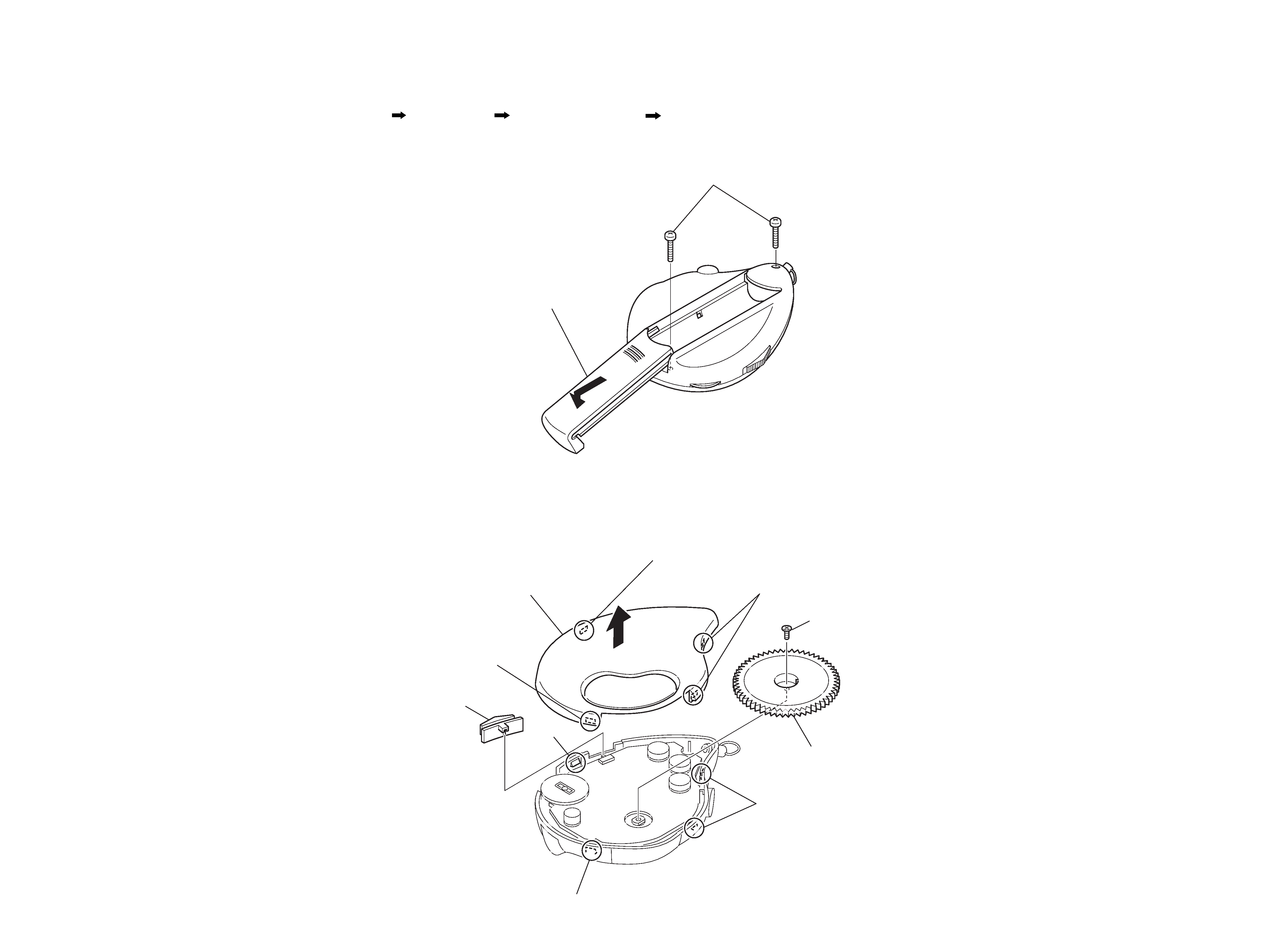
Note :
Follow the disassembly procedure in the numerical order given.
· The equipment can be removed using the following procedure.
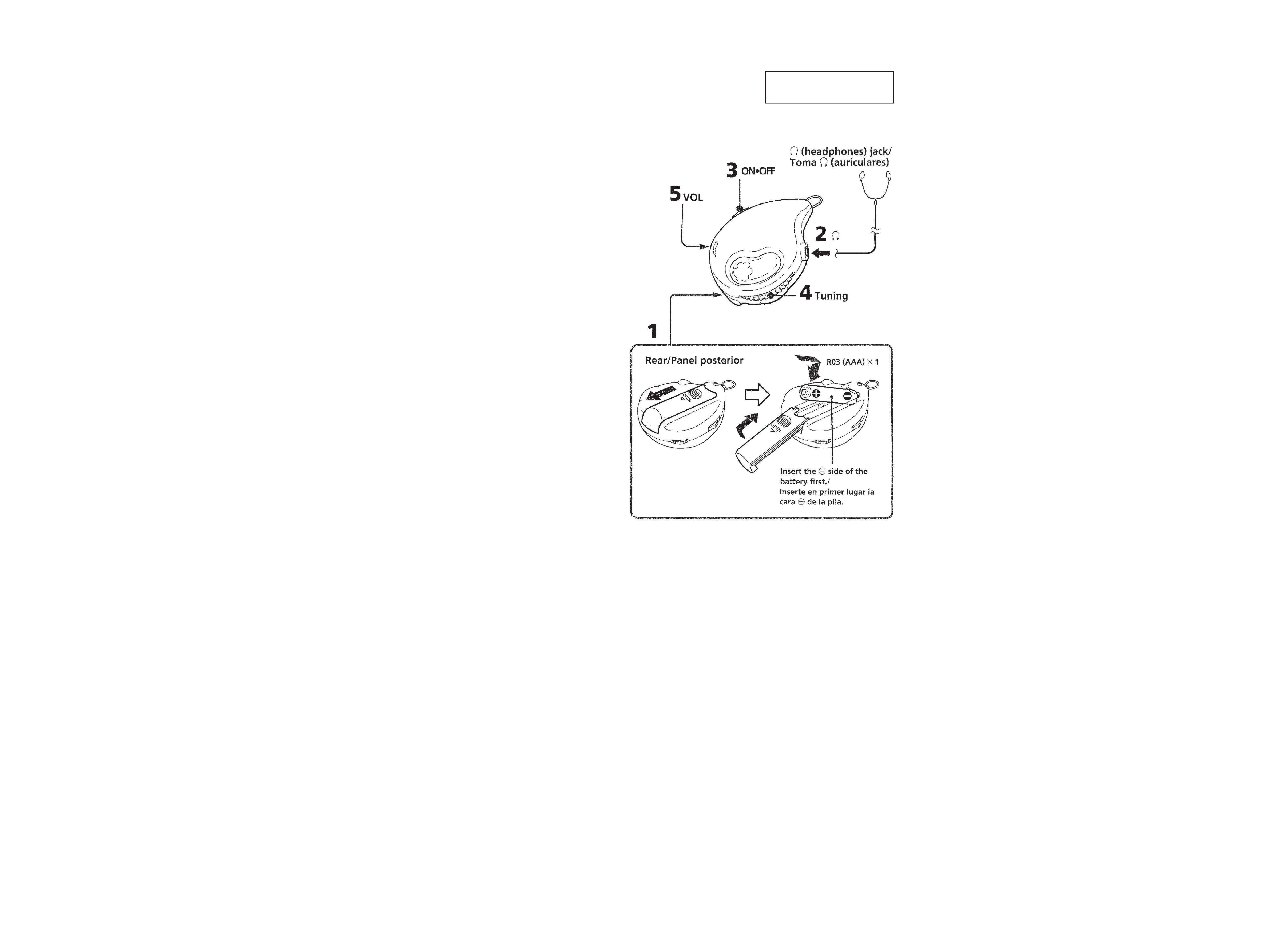
2-2. CABINET (FRONT), KNOB (TUNE)
Lid ,Battery Case
Cabinet (Front), Knob (Tune)
Main Board
Set
2
Two screws (B1.7
× 8)
1
Slide Lid, Battery Case in
the direction of the arrow.
6
Screw (P1.7
× 2.5)
claw
two claws
7
Knob (Tune)
claw
5
Knob (Power)
3
Release from the claw.
4
Remove the Cabinet (Front)
in the direction of the arrow.
2
Release them
from the two claws.
1
Release from the claw.
10
8
88
96
2-1. LID, BATTERY CASE

-- 4 --
2-3. MAIN BOARD
2
Remove the MAIN board
in the direction of the arrow.
1
Remove the leads at the two
points of battery terminals
(+)/(-) by unsoldering.
Lead wire (white)
Lead wire (red)
SRF-QT1
-- 5 --
-- 6 --
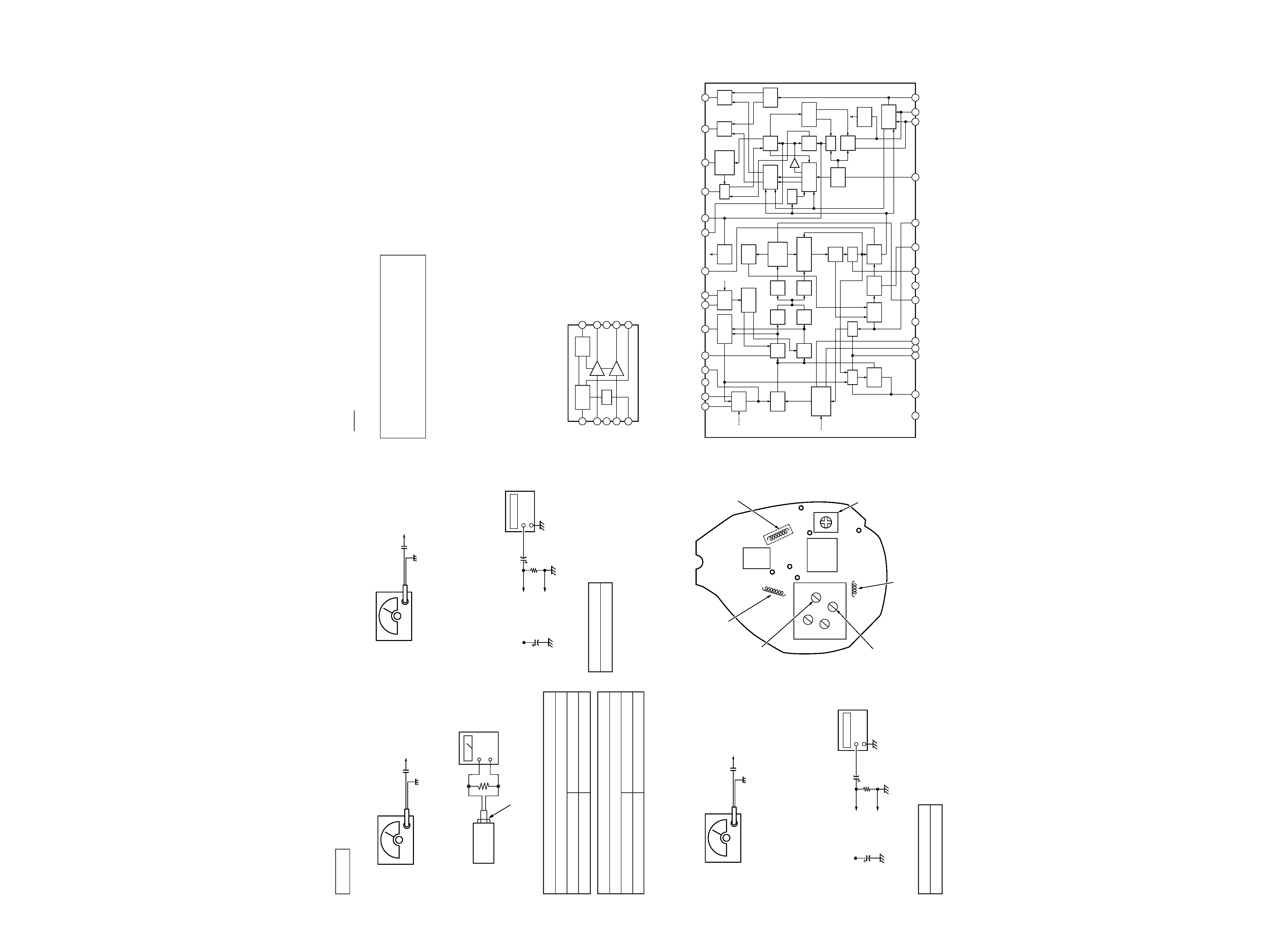
· Repeat the procedures in each adjustment several times.
FM TRACKING ADJUSTMENT
Adjust for a maximum reading on level meter.
L1
86.5MHz
CT1
109.5MHz
FM VCO Adjustment
Procedure :
1. Connect frequency counter to the positions shown below.
2. Tune the set to 98 MHz.
3. Adjust L4 so that the value of the frequency counter reading
becomes 38 kHz.
Specification Value :
Frequency counter
37.95 38.05 kHz
0dB=1µV
Adjustment Location: MAIN board (Side B)
FM FREQUENCY COVERAGE ADJUSTMENT
Adjust for a maximum reading on level meter.
L6
86.5MHz
CT2
109.5MHz
SECTION 3
ELECTRICAL ADJUSTMENT
0.01
µF
FM RF signal
generator
to ANT (TP6)
75kHz (100%) amplitude modulation
by 1kHz signal.
Output level : as low as possible
16
Set
+
Level meter
Headphones jack (J1)
0.01
µF
FM RF signal
generator
to ANT (TP6)
Carrier frequency : 98MHz
Modulation : no modulation
Output level : 0.1V (100dB)
Frequency counter
1
µF
+
100k
TP9
TP (GND)
TP8
10
µF
SECTION 4
DIAGRAMS
· IC BLOCK DIAGRAMS
IC1
CXA1129N
IC3
LA4535M
Note on Printed Wiring Board:
· X : parts extracted from the conductor side.
·
: parts extracted from the component side.
·
a
: Through hole.
· b : Pattern from the side which enables seeing.
Caution:
Pattern face side:
Parts on the pattern face side seen from
(SIDE A)
the pattern face are indicated.
Parts face side:
Parts on the parts face side seen from
(SIDE B)
the parts face are indicated.
Note on Schematic Diagram:
· All capacitors are in µF unless otherwise noted. pF: µµF
50 WV or less are not indicated except for electrolytics
and tantalums.
· All resistors are in
and 1/4 W or less unless otherwise
specified.
· C : panel designation.
· U : B+ Line.
· H : adjustment for repair.
· Power voltage is dc 1.5 V and fed with regulated dc power
supply from battery terminal.
· Voltages and waveforms are dc with respect to ground
under no-signal (detuned) conditions.
no mark : FM
· Voltages are taken with a VOM (Input impedance 10 M
).
Voltage variations may be noted due to normal produc-
tion tolerances.
· Signal path.
F
: FM
FM 2nd OSC Adjustment
Procedure :
1. Connect frequency counter to the positions shown below.
2. Tune the set to 98 MHz.
3. Adjust L2 so that the value of the frequency counter reading
becomes 57.1 MHz.
Specification Value :
0.01
µF
FM RF signal
generator
to ANT (TP6)
Carrier frequency : 98MHz
Modulation : no modulation
Output level : 0.1V (100dB)
Frequency counter
1
µF
+
100k
TP10
TP (GND)
TP8
10
µF
Frequency counter
56.85 57.35 MHz
L2 (Side A)
FM 2nd OSC
adjustment
L4
FM VCO
adjustment
L6
FM frequency coverage adjustment
CT2
FM frequency
coverage adjustment
CT1
FM tracking
adjustment
L1
FM tracking
adjustment
CV1
1
30
15
16
TP
(GND)
TP (GND)
TP9
10
1
6
5
TP6
TP10
IC3
IC1
TP8
1
2
6
8
FM/TV
RF AMP
FM/TV
MIX
FM/TV
1ST LOCAL
OSC
AFC
AM
RF AMP
OVER LOAD
AGC
MIX
1
MIX
2
PSN
1
PSN
2
AGC
AF AMP
LPF
DETUNE
DET
FM
LPF
AM
BPF
LOCAL
OSC
1/2
COUNTER
FM/TV
SELECT
FM
DISCRI
FM
LIMITTER
AMP
AM IF AMP
(FM TUN IND)
AM
DET
AGC
TUNING
IND
VCO
MUTE
SEP
CONTROL
ST.
DECORDER
INPUT
BUFF
VCO
LEVEL
CONTROL
BUFF
AMP
DC
AMP
PD
SYNC
DET
R CH
AMP
L CH
AMP
LOAD
SELECT
1/2
COUNTER
FM/AM
SELECT
M/ST.SW
ST.IND
FM/TV
30 29
25
24 23
26
28
27
22
20
3 4 5
7
9
10
11
12
13 14
15
16
17
18
19
21
FM/AM
FM/TV
38KHz
0
/2
FM/TV
FM/AM
19KHz
/2
19KHz
0
38KHz
FM
IN
TV
IN
NC
FM
RF
GAIN
ADJ
OL
AGC
2ND
OSC
AM
OSC
TUN
IND
PLL1
PLL2
VCO
OSC
VCO
CONT
R
OUT
L
OUT
ST
IND
PD2
PD1
MPX
IN
DET
OUT
MUTE
AGC2
NC
FM
IF
NC
TV
OSC
FM
OSC
AGC1
AM
IN
NC
POWER
SWITCH
MUTE
BIAS
AMP
AMP
1
2
3
4
5
6
7
8
9
10 MUTE
R-OUT
GND
L-OUT
VCC
PWR
R-IN
GND
L-IN
REG