MICROFILM
SERVICE MANUAL
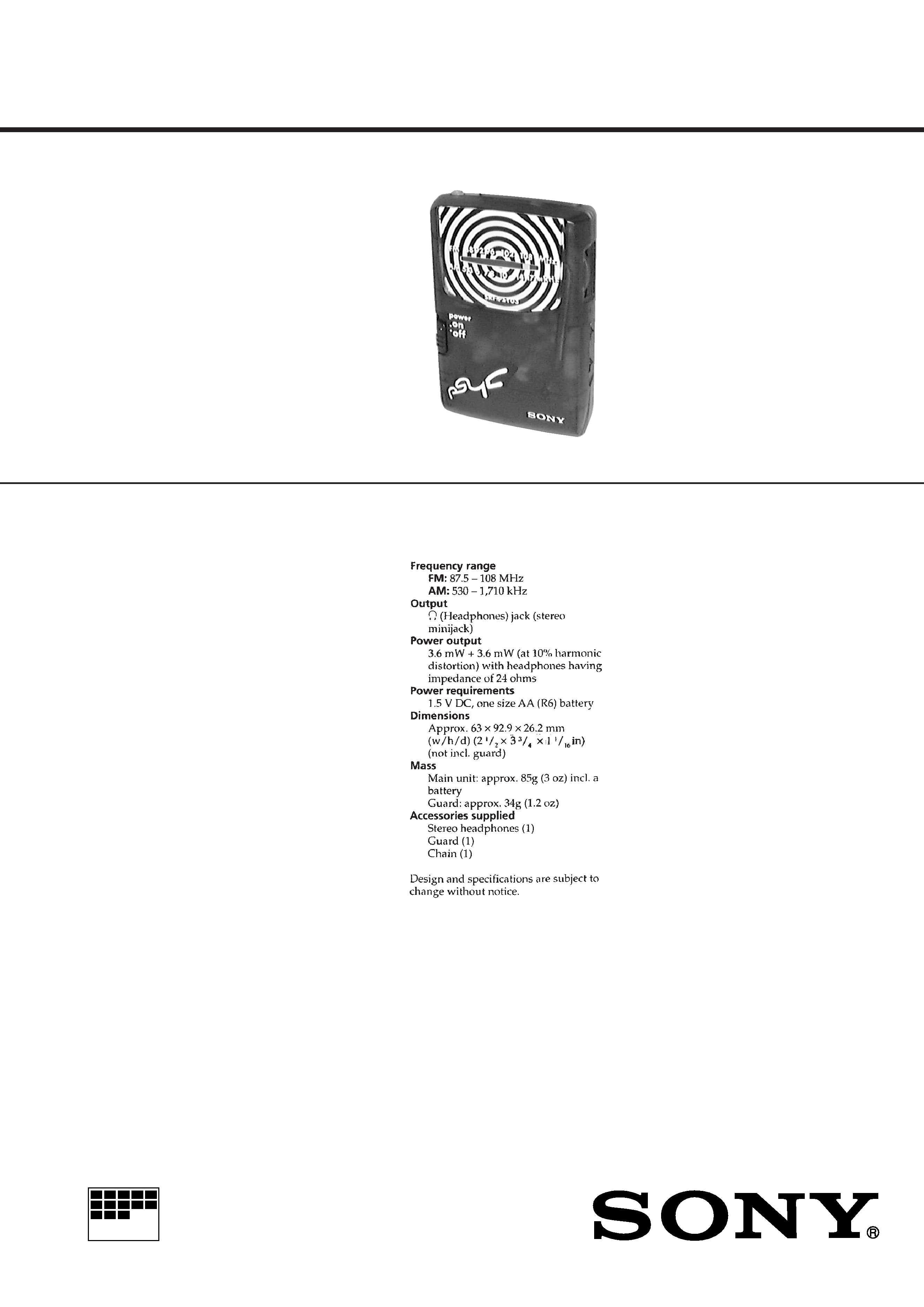
FM STEREO/AM RADIO
US Model
SPECIFICATIONS
SRF-PSY03
Photo: Violet model

2
TABLE OF CONTENTS
1.
GENERAL ................................................................... 3
2.
DISASSEMBLY ......................................................... 4
3.
ELECTRICAL ADJUSTMENTS ......................... 5
4.
DIAGRAMS
4-1. Block Diagram ................................................................
7
4-2. Printed Wiring Board ......................................................
9
4-3. Schematic Diagram ......................................................... 11
5.
EXPLODED VIEW ................................................... 13
6.
ELECTRICAL PARTS LIST ............................... 14
Notes on chip component replacement
· Never reuse a disconnected chip component.
· Notice that the minus side of a tantalum capacitor may be dam-
aged by heat.
3
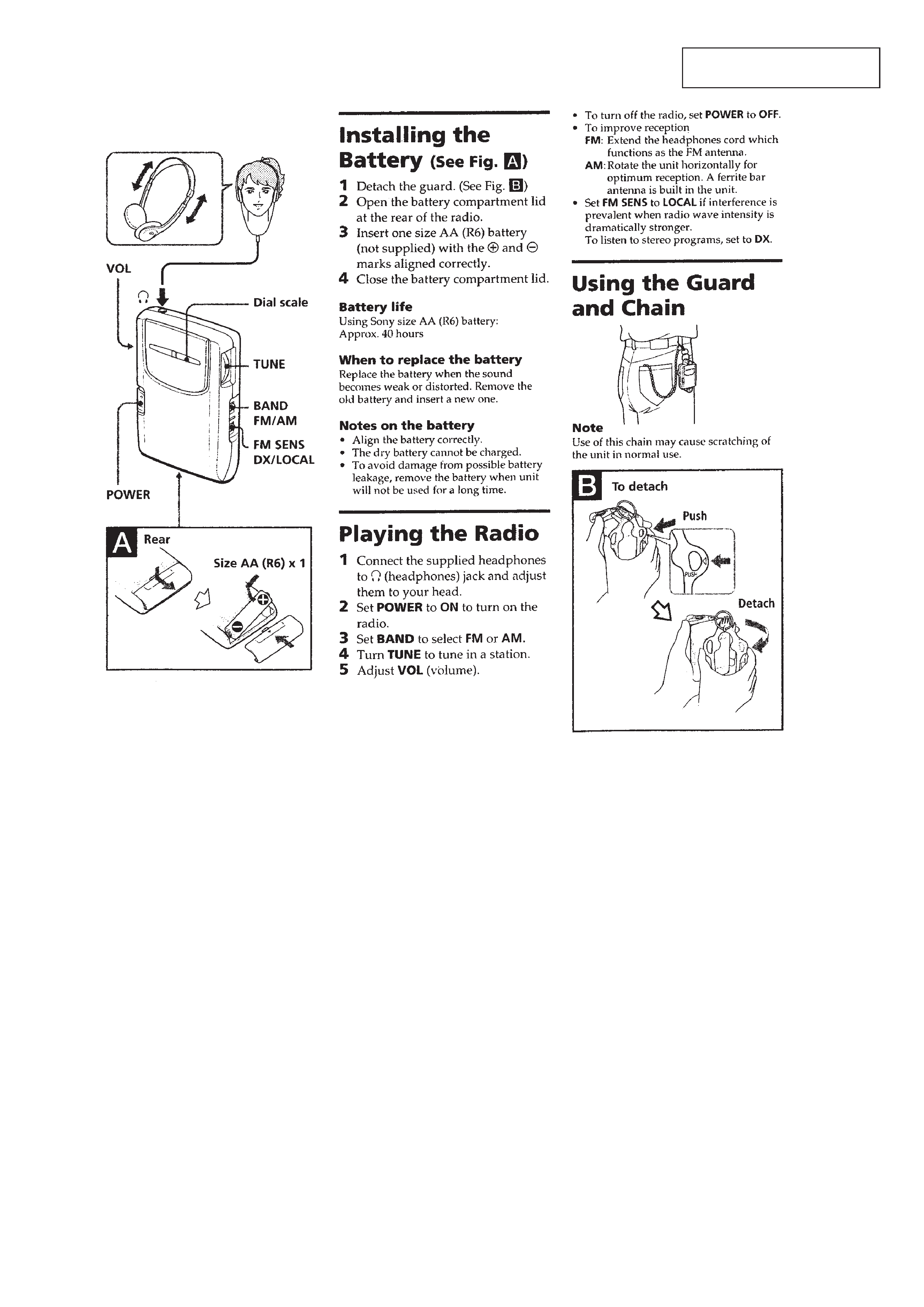
SECTION 1
GENERAL
This section is extracted from
instruction manual.
4
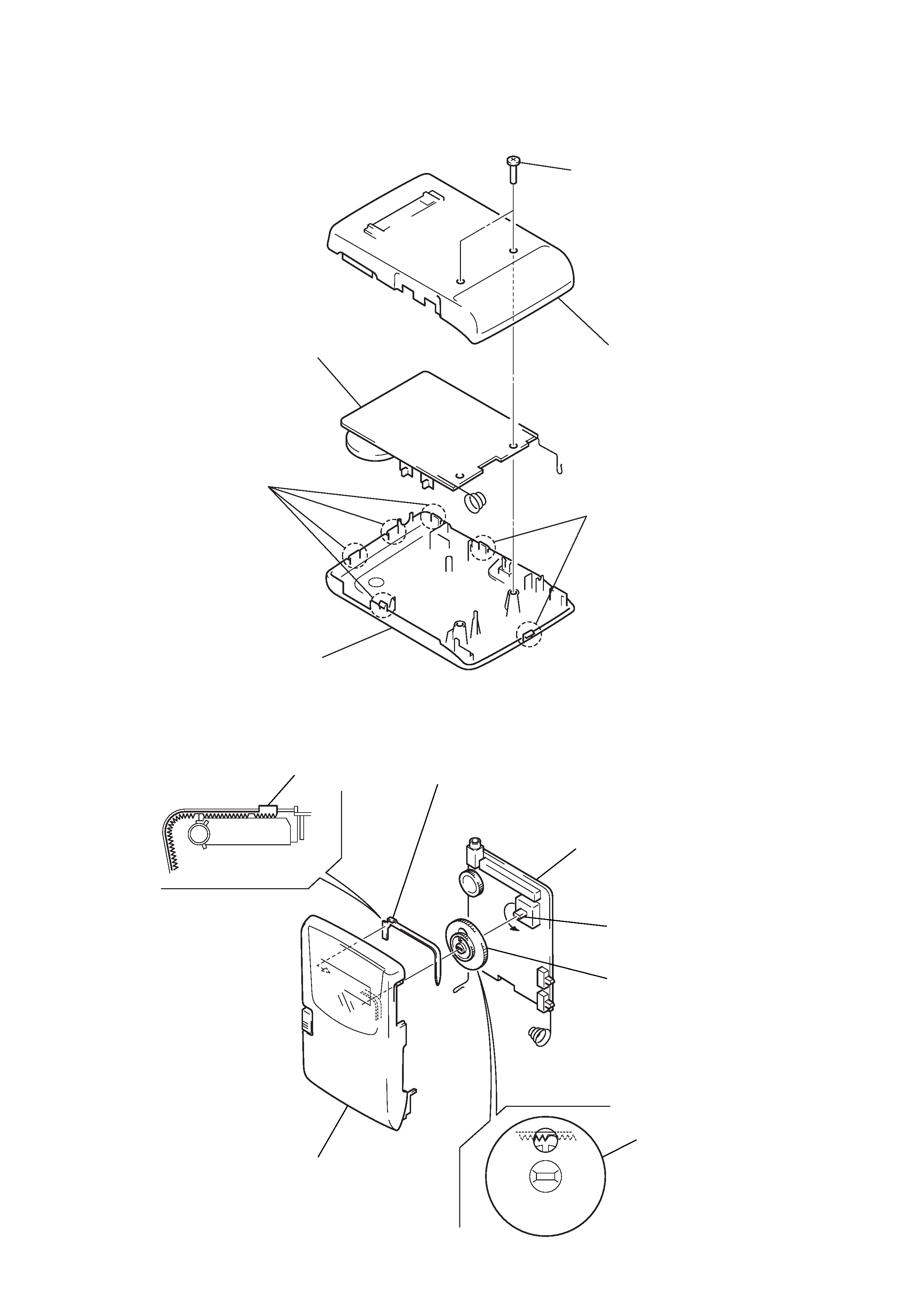
MAIN BOARD
Note: Follow the disassembly procedure in the numerical order given.
SECTION 2
DISASSEMBLY
DIAL POINTER SETTING
Note: Follow the assembly procedure in the numerical order given.
1 two screws
(P2
× 8)
4 main board
2 four claws
3 cabinet (rear)
2 two claws
5 cabinet (front)
pointer
1 Mount the pointer as
shown in the figure
A.
4 main board
cabinet (front)
3 Turn CV1 fully in the
arrow direction.
2 Mount the knob (TUNE)
as shown in the figure
B.
knob (TUNE)
fig.
B
fig.
A
5
0 dB = 1 µV
[AM]
Setting:
BAND switch: AM
[FM]
Setting:
BAND switch: FM
· Repeat the procedures in each adjustment several times, and
the frequency coverage and tracking adjustments should be fi-
nally done by the timmer capacitors.
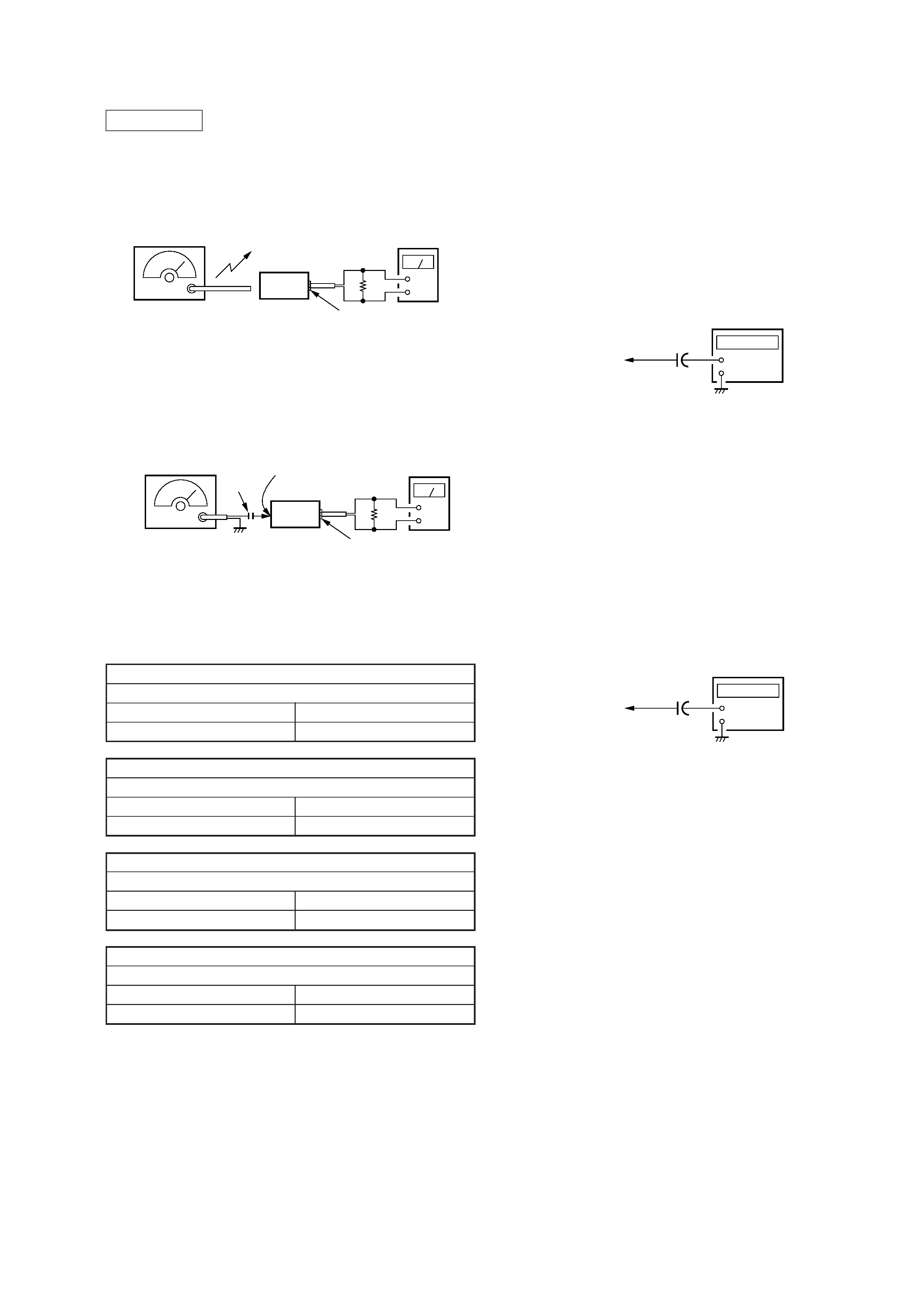
SECTION 3
ELECTRICAL ADJUSTMENTS
AM FREQUENCY COVERAGE ADJUSTMENT
Adjust for a maximum reading on level meter
L3
520 kHz
CT1 (3/4)
1,750 kHz
AM TRACKING ADJUSTMENT
Adjust for a maximum reading on level meter
L5
600 kHz
CT1 (4/4)
1,400 kHz
FM FREQUENCY COVERAGE ADJUSTMENT
Adjust for a maximum reading on level meter
L6
86.5 MHz
CT1 (1/4)
109.5 MHz
FM TRACKING ADJUSTMENT
Adjust for a maximum reading on level meter
L1
86.5 MHz
CT1 (2/4)
109.5 MHz
2nd Local Frequency (57.1 MHz) Adjustment
Setting:
BAND switch: FM
Procedure:
1. Connect the frequency counter to TP (OSC).
2. Adjust L2 for 56.75 MHz reading on the frequency counter.
Specification values: 56.5 to 57.0 MHz
Connection:
FM STEREO (38 kHz) Adjustment
Setting:
BAND switch: FM
Procedure:
1. Connect 10 µF Capacitor between TP (38 kHz) and TP (GND).
2. Connect the frequency counter to TP (VCO).
3. Adjust L4 for 38 kHz reading on the frequency counter.
4. Disconnect 10 µF Capacitor in step 1.
Specification values: 37.95 to 38.05 kHz
Connection:
AM RF signal
generator
30% amplitude
modulation by
400 Hz signal
Output level: as low as possible
Put the lead-wire
antenna close to
the set.
+
level meter
set
24
2 jack (HPJ1)
FM RF signal
generator
22.5 kHz frequency
deviation by 400 Hz
signal
Output level: as low as possible
+
level meter
2 jack (HPJ1)
TP (RF IN)
set
24
0.01
µF
1
µF
50 V
TP (OSC)
+
+
frequency counter
1
µF
50 V
TP (VCO)
+
+
frequency counter