SRF-M95
AEP Model
Chinese Model
E Model
Australian Model
Tourist Model
SERVICE MANUAL
FM STEREO/AM PLL SYNTHESIZED RADIO
SPECIFICATIONS
Ver 1.2 2002. 05
Time display: 24-hour system
Frequency range:
Band
Frequency range
Channel step
FM
Panama model :
Except Panama, Tourist model :
87.5 - 108 MHz
0.1 MHz
AM
530 -1 710 kHz
10 kHz
FM
87.5 - 108 MHz
0.05 MHz
AM
531 -1 602 kHz
9 kHz
Tourist model :
FM
76.0 - 108 MHz
0.05 MHz
AM
531 -1 710 kHz
9 kHz
Output: 2 (headphones) jack (
3.5 mm, stereo
minijack)
Power output: 2.5 mW + 2.5 mW (at 10 % harmonic
distortion)
Power requirements: 1.5 V DC, one R03 (size AAA)
battery
Auto Power off function: Approx. 30 minutes, 60
minutes, 90minutes, 120 minutes, and off
Dimensions: Approx. 39
× 83.8 × 20.4 mm (w/h/d)
(Approx. 1 9/
16 × 3
3/
8 ×
13/
16 inches) incl.
projecting parts and controls
Mass: Approx. 57.5 g (2 oz.) incl. battery and the
Accessories supplied
Stereo headphones (1)
headphones
Design and specifications are subject to change
without notice.
Battery Life (Approx. hours)
When using
FM
AM
Sony alkaline LR03(size AAA) 40
54
Sony R03(size AAA)
18
26
Sony Corporation
Personal Audio Company
Published by Sony Engineering Corporation
9-873-067-13
2002E1600-1
© 2002.05
2
SRF-M95
Notes on chip component replacement
· Never reuse a disconnected chip component.
· Notice that the minus side of a tantalum capacitor may be
damaged by heat.
Flexible Circuit Board Repairing
· Keep the temperature of soldering iron around 270°C
during repairing.
· Do not touch the soldering iron on the same conductor of the
circuit board (within 3 times).
· Be careful not to apply force on the conductor when soldering
or unsoldering.
SECTION 1
GENERAL
This section is extracted
from instruction manual.
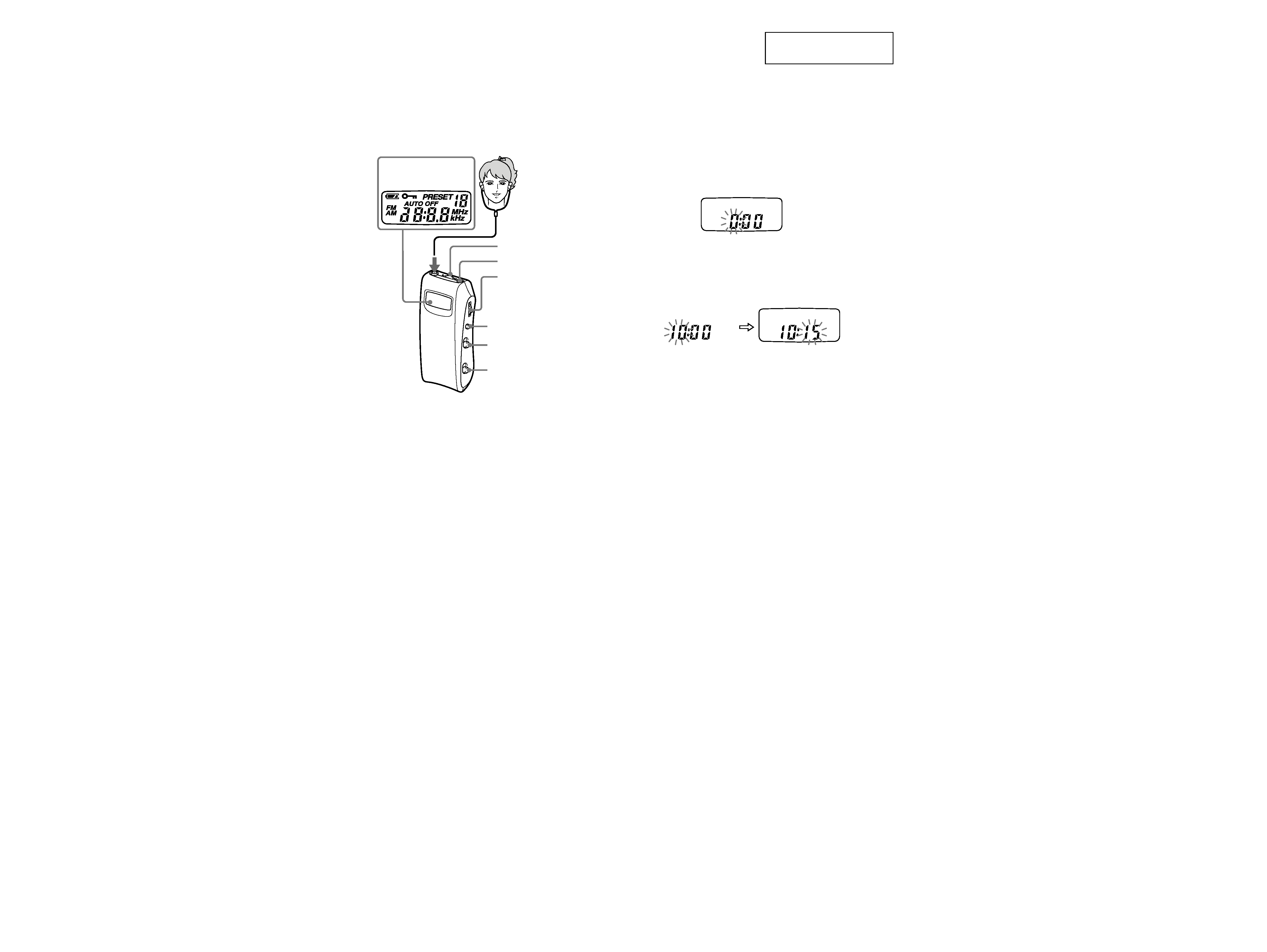
Setting the Clock
The time display of this clock is a 24-hour system.
1 Press POWER to turn off the power.
2 Press and hold down the jog lever for
more than 2 seconds until "0"starts
flashing.
3 Slide or keep sliding the jog lever up or
down to adjust the hour and press the
jog lever.
If you keep sliding the jog lever up or down,
the number changes rapidly.
0:00=midnight, 12:00=noon.
4 Slide the jog lever up or down to adjust
the minutes and press the jog lever.
":" starts flashing and the clock starts
operating.
To set the current time exactly to the second,
adjust the minute and then press the jog lever
in time with a time signal (such as the
telephone time signal).
To cancel the setting, press MODE.
Note
Once you start setting the clock, you must perform each
step within 60 seconds, or the clock setting mode will be
cancelled.
POWER
Jog Lever
(selection/decision)
Molette (sélection/décision)
Palanca de lanzadera
(selección/decisión)
MODE
HOLD
MEGA BASS
Display Window
Afficheur
Visualizador
2
VOL
Front
Face avant
Parte frontal
3
SRF-M95
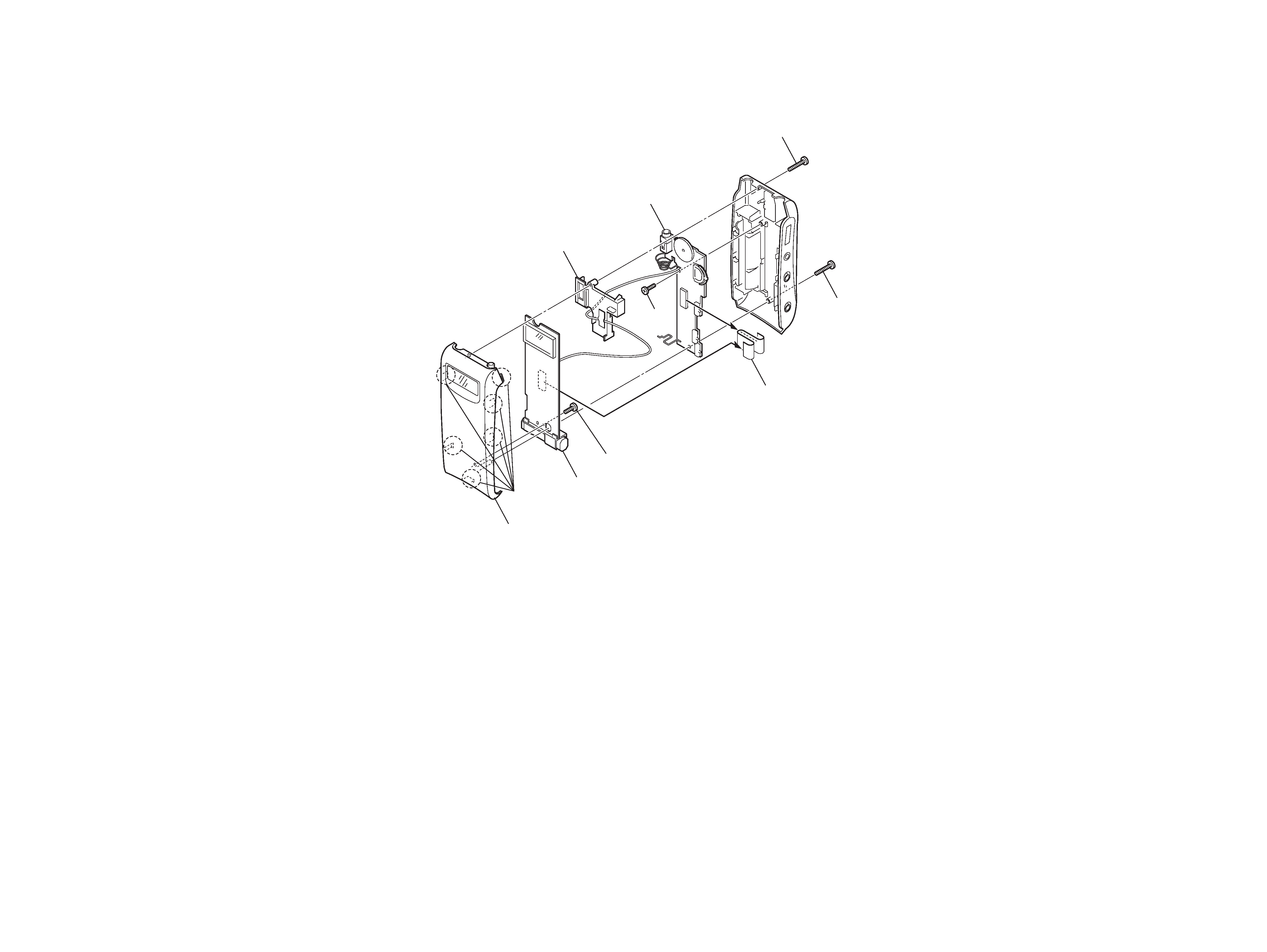
SECTION 2
DISASSEMBLY
Note : Follow the disassembly procedure in the numerical order given.
2-1. MAIN BOARD, SUB BOARD
1
Screw (1.4
× 10)
1
Screw (1.4
× 10)
9
SUB board
7
Cover (Jack)
1
Screw (1.4
× 10)
5
Flexible board
4
Screw
6
MAIN board
3
Cabinet (front) assy
2
Six claws
8
Screw
4
SRF-M95
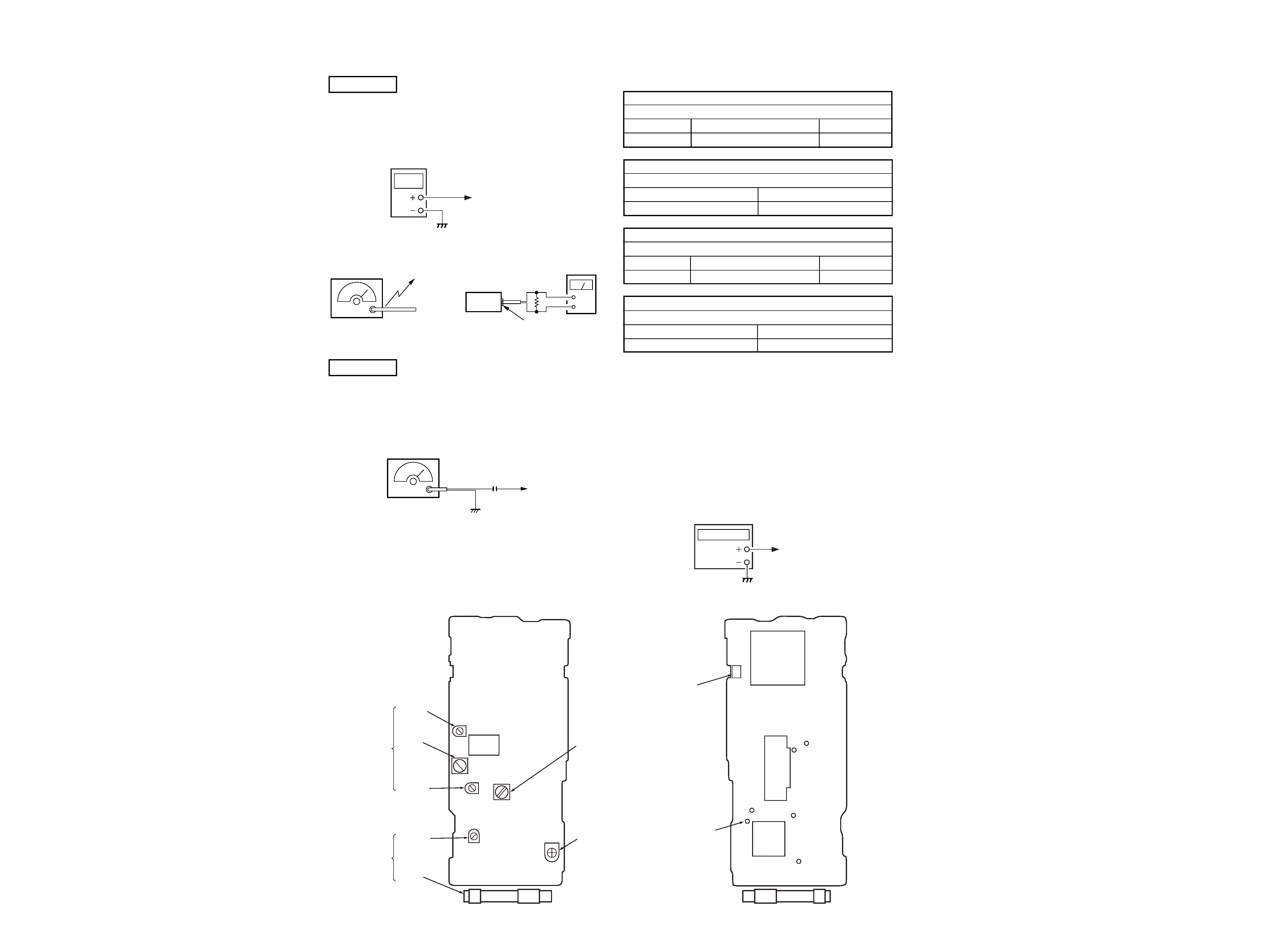
SECTION 3
ADJUSTMENTS
Setting:
BAND switch: AM
Connection:
For AM frequency coverage adjustment and FM frequency coverage check.
AM Section
digital
voltmeter
TP (VT)
Connection:
AM RF signal
generator
30% amplitude modulation by
400 Hz signal.
Output level: as low as possible
Put the lead-wire
antenna close to
the set.
level meter
set
headphone jack (i)
16
+
FM Section
FM RF signal
generator
22.5 kHz frequency deviation
by 400 Hz signal.
Output level: as low as possible
0.01
µF
TP (ANT)
FM VCO Adjustment
Setting:
BAND switch:
FM
FM SENS switch: DX
Procedure:
1.
Turn off the FM RF signal generator.
2.
Put a capacitor (100
µF) between pin ws (IC201) and GND.
3.
Put a resistor (100 k
) between TP (VCO) and GND.
4.
Tune the set to 87.5 MHz.
5.
Adjust RV201 for 19 kHz
± 0.05kHz reading on the frequency
counter.
AM FREQUENCY COVERAGE ADJUSTMENT
Adjust for a reading on digital voltmeter.
T201
531 kHz (530 kHz) [531 kHz]
1.3V
± 0.1V
Confirm
1,602 kHz (1,710 kHz) [1,710 kHz]
10 V or less
AM TRACKING ADJUSTMENT
Adjust for a maximum reading on level meter.
CT201
1485 kHZ (1480 kHz)
L201
585 kHz (590 kHz)
FM FREQUENCY COVERAGE CHECK
Check a reading on digital voltmeter.
Confirm
87.5 MHz [76.0 MHz]
3.5V [0.9 V] or more
Confirm
108.0 MHz
11V or less
FM TRACKING ADJUSTMENT
Adjust for a maximum reading on level meter.
CT101, CT102
108.0 MHZ
L104
87.5 MHz [76.0 MHz]
(
) : Panama model [
] : Tourist model
Connection:
frequency counter
TP (VCO)
Setting:
BAND switch:
FM
FM SENS switch: DX
Connection:
Adjustment Location
[MAIN BOARD]
(SIDE B)
[MAIN BOARD]
(SIDE A)
IC401
CN401
IC201
GND
TP(VCO)
GND
GND
TP(ANT)
TP(VT)
TP(pin ws)
IC101
CT101
CT102
CT201
L201
L104
FM TRACKING
Adjustment
AM TRACKING
Adjustment
T201
AM FREQUENCY
COVERAGE Adjustment
RV201
FM VCO
Adjustment
5
5
SRF-M95
SECTION 4
DIAGRAMS
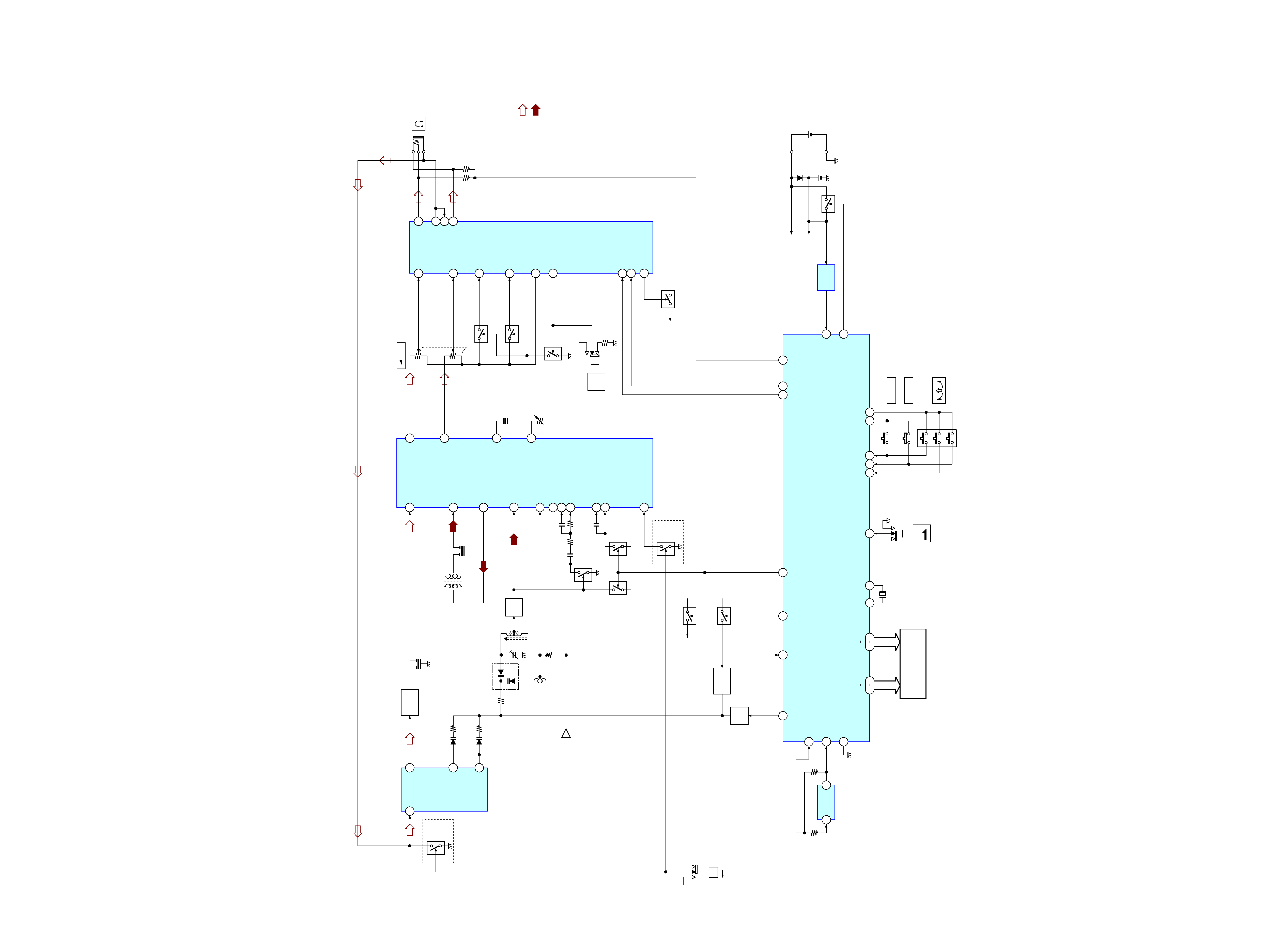
4-1. BLOCK DIAGRAM
FM/AM RF,IF AMP
IC201
T202
AM MIX
CF202
450kHz
MIX OUT
4
FM IF IN
3
AM IF IN
6
AM OSC
L OUT 14
R OUT 15
ON
OFF
: FM
· Signal Path
· RCH is omitted
: AM
RF IN
1
6
MIX
8
RF OUT
5
OSC
FM FRONT END
IC101
D101
FM IF
AMP
Q102
CF101,102
10.7MHz
L201
BAR ANT
AM RF
24
Q201
RF
AMP
T201
AM OSC
2
D201
7
QUAD
17
VCO
VCO
RV201
CF203
10.7MHz
AUDIO
POWER AMP
IC301
40
DO
TU VCC
Q101
LOCAL
/DX
EXCEPT
JE
MODEL
D102
Q103
TU VCC
LPF1
16
Q204
LOCAL
/DX
JE MODEL
FM
DX
LOCAL
OFF
ON
TU VCC
L.P.F
Q403
CT201
DET OUT
22
PILOT IN
21
MPX IN
20
Q205
LPF 2A
18
LPF 2B
19
Q203
BAND
TU VCC
TU VCC
Q202
TU VCC
Q303
S304
Q302(1/2)
IN L
27
Q302(2/2)
IN R
28
S305
MEGA
BASS
VOL
RV301
TU VCC
NF L
26
NF R
29
REF OUT
3
BST SW
43
PW SW
42
MT SW
41
Q301
TU VCC
VCC
BASE
18
OUT L 22
OUT C 21
OUT R 20
AGC IN 35
J301
TU VCC
Q104,105
IC101
+B
DC-DC
CONV
T401
Q402,405
VCC
Q401
38
OSC
IN
31
DDC
ON
52
BAND
53
AM
PON
50
MUTE
28
BEEP
X
OUT
55
LCD1
LIQUID CRYSTAL
DISPLAY
X
IN
56
X401
75kHz
14
COM1 COM4
516
S1 S12
INT2
34
VDD
IF
COUNTER
1
2
INT1
35
IF INT2
36
VCC
IC402
HOLD
SW
26
HOLD
S303
KR1
23
DIGITAL TUNING
SYSTEM CONTROL
IC401
POWER
KR2
24
KR3
25
KS1
21
KS2
-2
S401
MODE
S302
-1
-3
22
S301
JOG
DRY BATTRY
SIZE "AAA"
(IEC DESIGNATION R03)
1PC 1.5V
Q406
VDD
IC403
VCC
RESET
RESET 54
POWER ON 51
· Abbreviation
JE
: Tourist model.
Ver 1.1 2002. 02