MICROFILM
SERVICE MANUAL
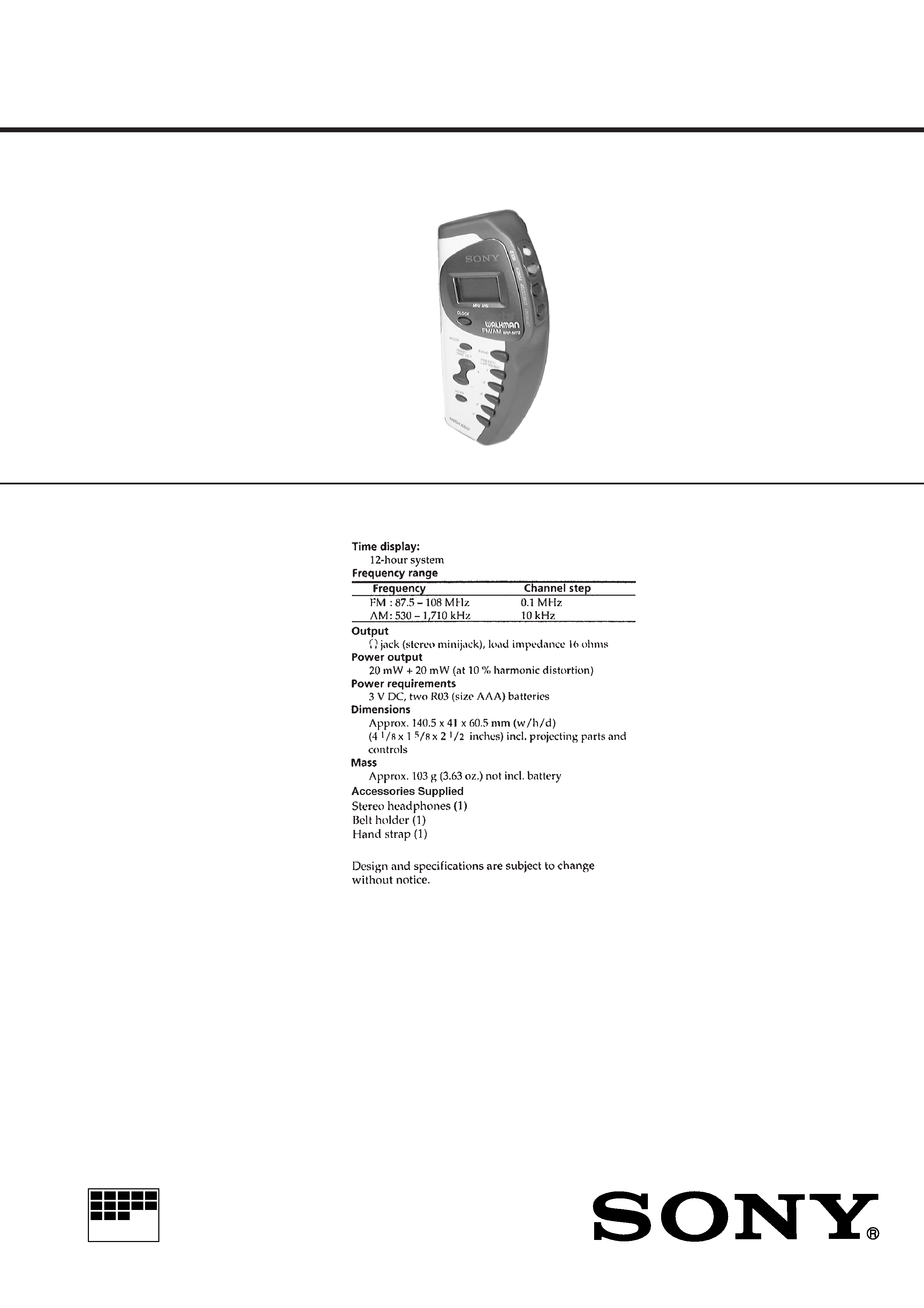
FM STEREO/AM PLL SYNTHESIZED RADIO
US Model
Panama Model
SPECIFICATIONS
SRF-M73
Ver 1.0 1999. 03

2
TABLE OF CONTENTS
1.
SERVICING NOTES ............................................... 2
2.
GENERAL ................................................................... 3
3.
DISASSEMBLY ......................................................... 4
4.
ELECTRICAL ADJUSTMENTS ......................... 6
5.
DIAGRAMS
5-1. Block Diagram ................................................................
8
5-2. Printed Wiring Boards ..................................................... 10
5-3. Schematic Diagram ......................................................... 13
5-4. IC Pin Function Description ........................................... 18
6.
EXPLODED VIEWS ................................................ 19
7.
ELECTRICAL PARTS LIST ............................... 20
Forced Reset
The system microprocessor can be reset in the following proce-
dure.
Use these procedure when the unit cannot be worked normally
due to the overrunning of the microprocessor, etc.
Procedure:
1. Set to radio OFF.
2. While pressing the [SCAN] button, press two buttons of [START/
STOP] and [BAND] simultaneously for 5 seconds.
3. The unit is reset, and display blinking "AM 12:00".
SECTION 1
SERVICING NOTES
3
SECTION 2
GENERAL
This section is extracted from
instruction manual.
4
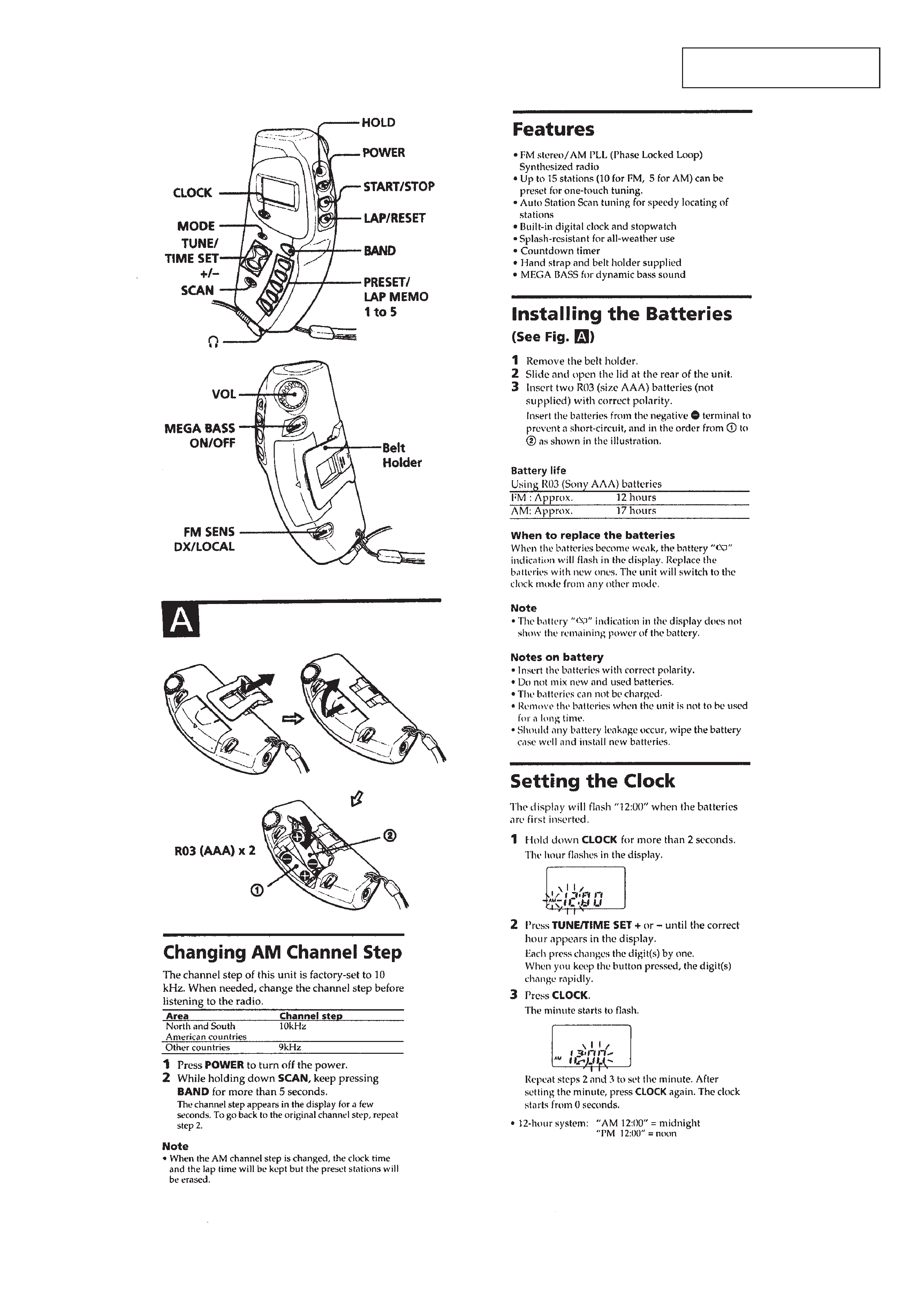
CABINET (FRONT)/(REAR) ASSY
KEY BOARD
· This set can be disassembled in the order shown below.
SECTION 3
DISASSEMBLY
Set
Key Board
Main Board
Knob (A)
Cabinet (Rear) Assy
Cabinet (Front) Assy
2 three screws
(B1.7
× 8)
2 two screws
(B1.7
× 8)
1 Remove the battery case lid
of the arrow.
3 cabinet (front) assy
4 cabinet (rear) assy
1 three claws
2 Open the key board
to direction of the arrow.
1 four claws
Note: Follow the disassembly procedure in the numerical order given.
5
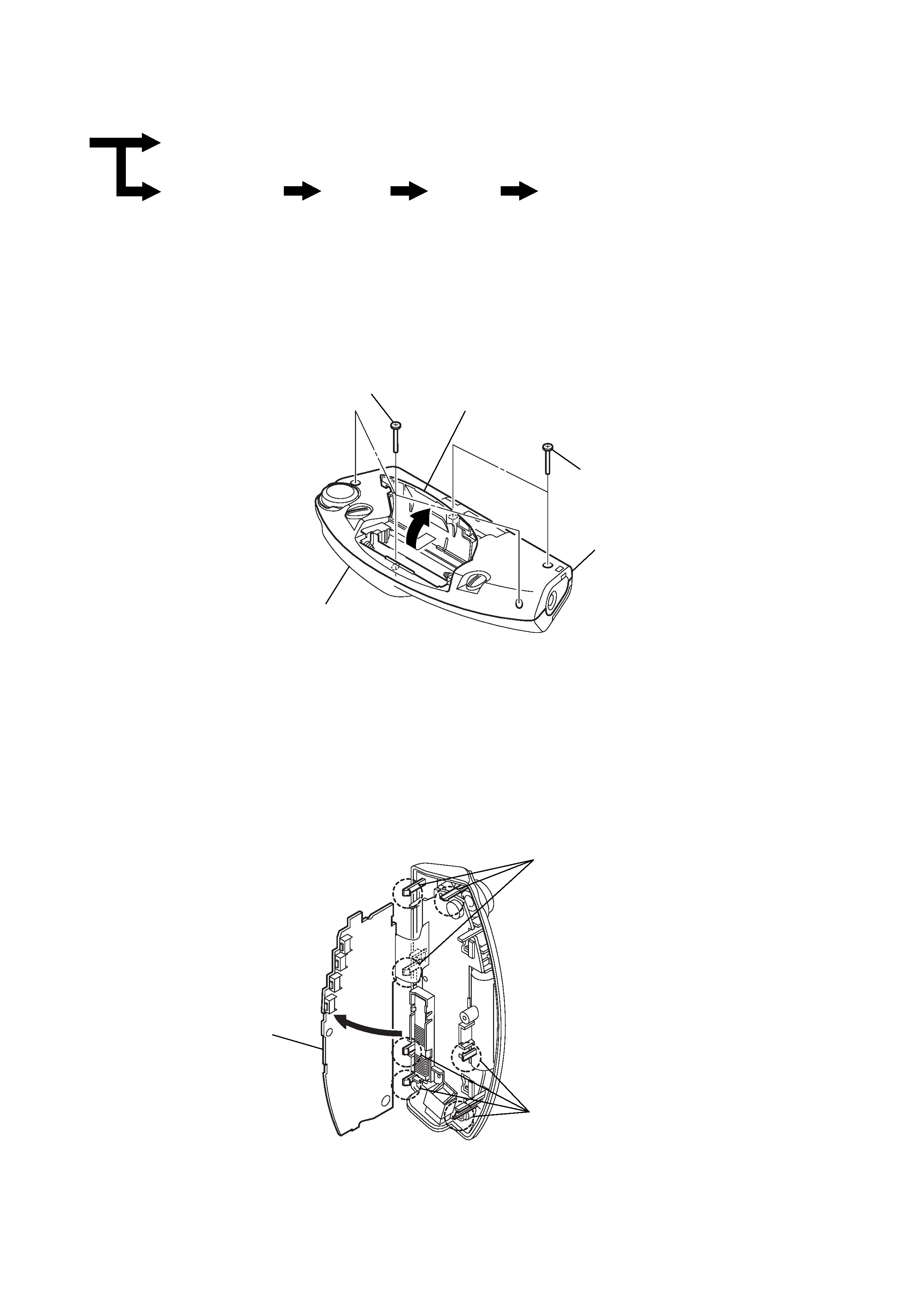
MAIN BOARD
KNOB (A)
Note: Check that two switch (S1,
S2) is latched with two
adaptors when carrying
out installation.
2 screw
(B1.7
× 8)
1 Remove two solders.
3 knob (vol)
4 two claws
S1
S2
5 main board
2 two knobs (A)
1 claw
1 claw
3 two adaptors