SERVICE MANUAL
TV/WEATHER/FM STEREO/AM
PLL SYNTHESIZED HEADPHONE RADIO
US Model
SPECIFICATIONS
SRF-HM03V
Ver 1.0 2004.04
9-877-737-01
Sony Corporation
2004D05-1
Personal Audio Company
© 2004.04
Published by Sony Engineering Corporation
Time display: 12-hour system
Frequency range:
Band
Range
Channel step
TV
2 - 13 ch
1 channel
WEATHER
1 - 7 ch
1 channel
FM
87.5 - 108 MHz
0.1 MHz
AM
530 - 1 710 kHz
10 kHz
531 - 1 710 kHz
9 kHz
Headphone type: Dynamic
Power output: 7 mW + 7 mW (at 10 % harmonic distortion)
Power requirements: 1.5V DC, one size AAA (R03) battery
Mass: Approx. 156 g (5.6 oz) incl. a battery
Design
Supplied accessories: Operating instructions
and specifications are subject to change without notice.
Battery Life (Approx. hours)
(JEITA*)
TV
WEATHER
FM
AM
Sony alkaline size AAA (LR03) battery
33
33
37
57
Sony size AAA (R03) battery
14
14
16
26
* Measured by JEITA (Japan Electronics and Information Technology
Industries Association) standards.
The actual battery life may vary depending on the circumstance of the
unit.

2
SRF-HM03V
TABLE OF CONTENTS
1.
GENERAL ................................................................... 3
2.
DISASSEMBLY
2-1. Disassembly Flow ...........................................................
4
2-2. POWER Board ................................................................
4
2-3. Cable Setting ...................................................................
5
2-4. MICON Board, MAIN Board .........................................
5
2-5. Putting the Sheet (A) .......................................................
6
3.
ELECTRICAL ADJUSTMENTS ......................... 7
4.
DIAGRAMS
4-1. Note for Printed Wiring Boards
and Schematic Diagram ..................................................
8
4-2. Schematic Diagram .........................................................
9
4-3. Printed Wiring Boards MAIN/POWER Boards ...... 10
4-4. Printed Wiring Board MICON Board ..................... 11
5.
EXPLODED VIEWS
5-1. Cabinet (L) Section ......................................................... 14
5-2. Cabinet (R) Section ......................................................... 15
5-3. Board Section .................................................................. 16
6.
ELECTRICAL PARTS LIST ............................... 17
Notes on chip component replacement
·Never reuse a disconnected chip component.
· Notice that the minus side of a tantalum capacitor may be dam-
aged by heat.
3
SRF-HM03V
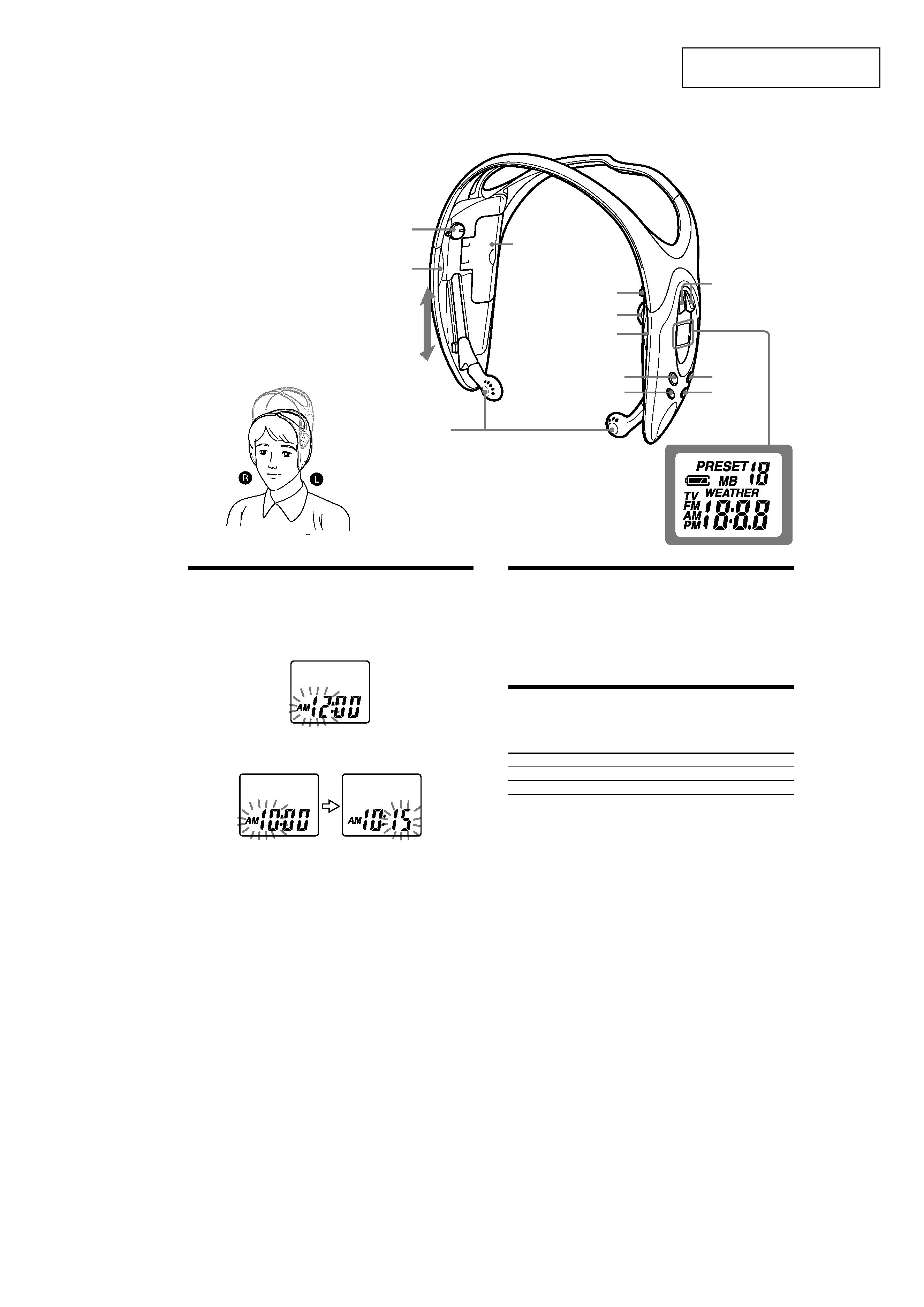
SECTION 1
GENERAL
This section is extracted from
instruction manual.
POWER ON/OFF
Driver Unit
TUNE +*2/--
Display
MEGA BASS/CLOCK
ENTER
MODE
BAND
VOL*1
TV/WB/FM SENS
DX/LOCAL
R (Right)
L (Left)
Battery
compartment lid
Light reflector (L)
This reflector
reflects car lights
at night for your
safety.
*1
There is a tactile dot beside volume to show the
direction to turn up the volume.
*2
The TUNE + button has a tactile dot.
Setting the Clock
The clock time display of this unit is a 12-hour system.
When the battery is first installed, AM 12:00 flashes in the display.
1 Set POWER to OFF to turn off the power.
2 Hold down MEGA BASS/CLOCK for more than 2 seconds
until AM 12 starts flashing.
3 Press TUNE + or to adjust the hour, then press MEGA BASS/
CLOCK.
If you hold down
TUNE + or --, the digit changes rapidly.
AM 12:00 = midnight, PM 12:00 = noon.
4 Repeat step 3 above to adjust the minute.
: starts flashing and the clock starts operating.
To set the current time exactly to the second, adjust the minute and then press
MEGA BASS/CLOCK to synchronize with a time signal (such as the
telephone time signal).
Note
If you do not press
TUNE + or --, or MEGA BASS/CLOCK within one minute,
the clock setting mode will be canceled.
Wearing the Headphone
Radio
(See fig
A)
1 Wear the
L side driver unit in your left ear and the R side in your
right ear as illustrated.
2 Adjust the position of the driver units for a comfortable fit.
Changing AM Channel Step
The AM channel step differs depending on areas. The channel step of this unit is
factory-set to 10 kHz. Change the settings as shown below to be able to listen to
the radio.
Area
Channel step
North and South American countries
10 kHz
Other countries
9 kHz
Note
When the AM channel step is changed, only the preset stations on the AM band
will be initialized.
1 Set POWER to OFF to turn off the power.
2 While holding down MODE, hold down TUNE + or for more
than 5 seconds.
The channel step will change and 9 kHz (or 10 kHz) will flash for 3
seconds in the display.
If you proceed to step
2 again, the channel step changes again.
Light reflector (R)
A
SRF-HM03V
4
· This set can be disassembled in the order shown below.
2-1.
DISASSEMBLY FLOW
SECTION 2
DISASSEMBLY
Note: Follow the disassembly procedure in the numerical order given.
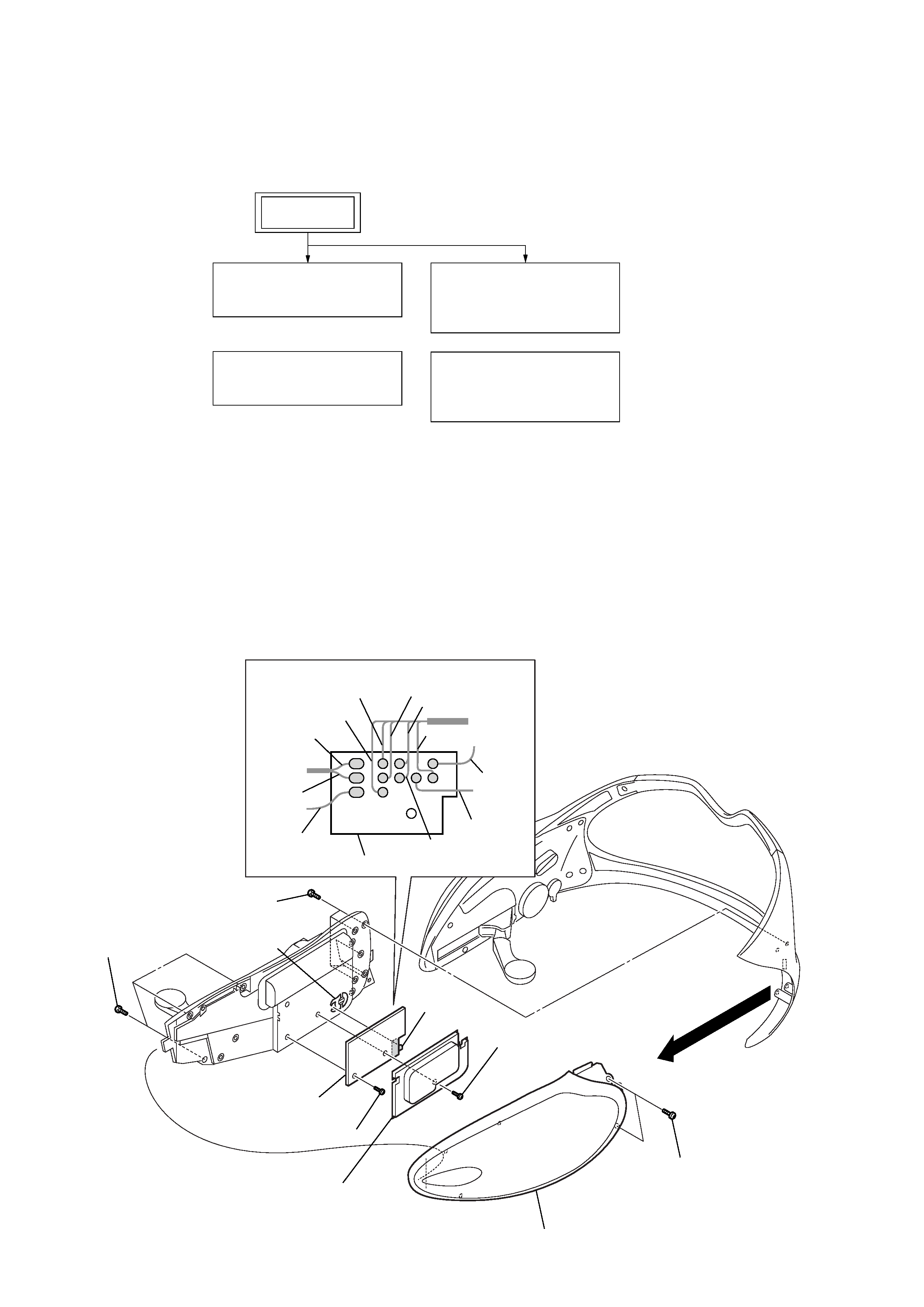
2-2.
POWER BOARD
2-2. POWER BOARD
(Page 4)
2-4. MICON BOARD,
MAIN BOARD
(Page 5)
2-5. PUTTING THE
SHEET (A)
(Page 6)
2-3. CABLE SETTING
(Page 5)
SET
1
six screws
(1.7)
8
Remove the eleven solders.
4
three screws
(B1.4)
3
two screws
(1.7)
5
cabinet assy front (L)
6
screw (B1.4)
9
screw (B1.4)
0
POWER board
7
lid (PWB BATT)
2
S401
knob
POWER board
red
yerrow
white
gray
red
natural
black
black
blue
blue
green
Note: When installing the POWER board, fit the knob and switch (S401).
SRF-HM03V
5
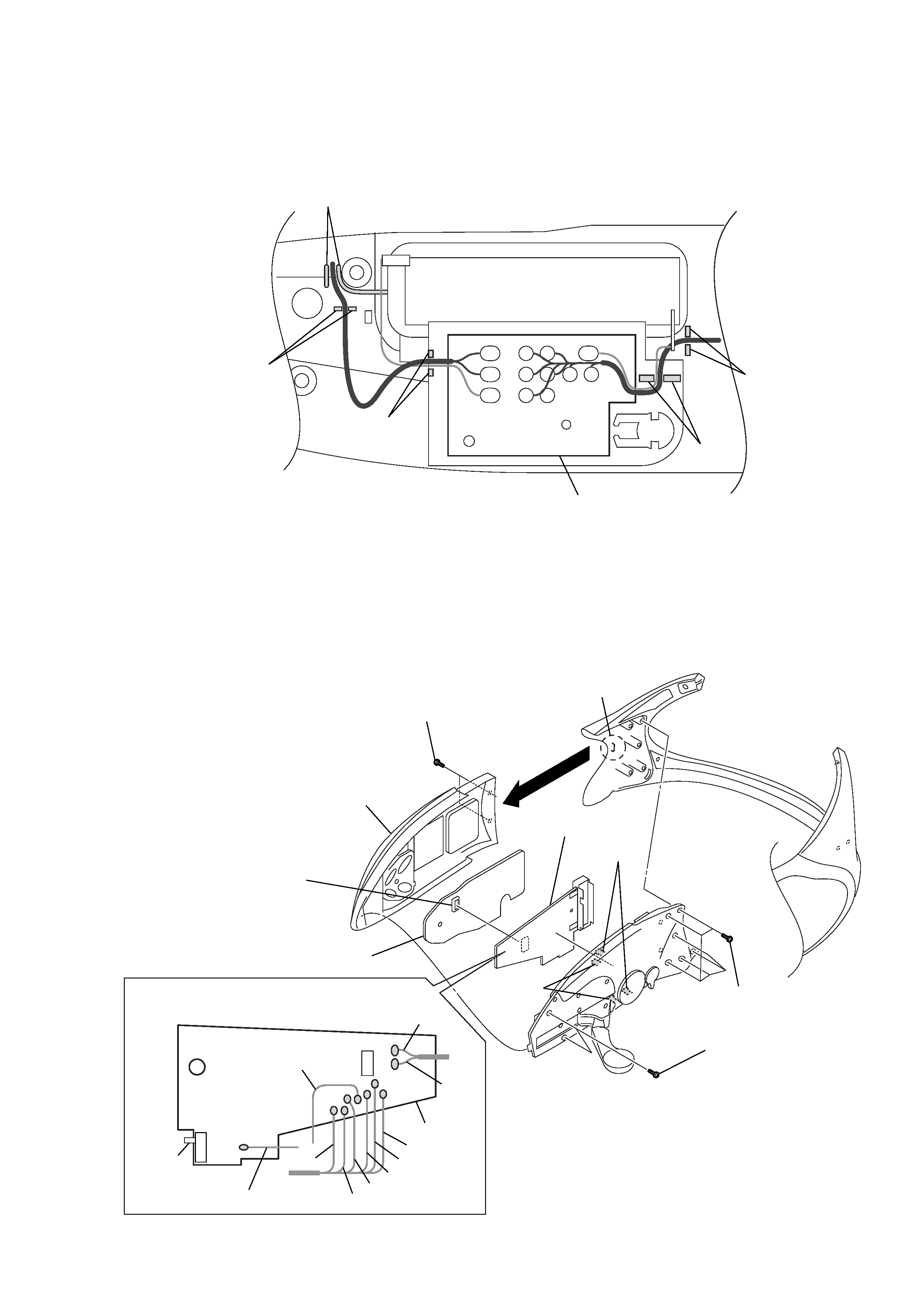
2-4.
MICON BOARD, MAIN BOARD
1
six screws
(1.7)
3
two screws
(1.7)
5
claw
q;
two claws
qa
two claws
4
two screws
(B1.4)
6
cabinet assy front (R)
8
MICON board
qs
MAIN board
2
9
Remove the ten solders.
MAIN board
gray
white
blue
blue
yerrow
red
black
black
S1
Note: When installing the MAIN board, fit the knob and switch (S1).
7
connector
(CN301)
green
natural
2-3.
CABLE SETTING
Note: When installing the POWER board, set the cables as shown figure.
POWER board
slit
slit
slit
slit
slit