Ver 1.0
1998.05
MICROFILM
SRF-H5
SERVICE MANUAL
FM STEREO / AM HEADPHONE RADIO
SPECIFICATIONS
US Model
Canadian Model
AEP Model
Australian Model
US, Canadian Model :
FM : 87.5 108 MHz
AM : 530 1,710 kHz
AEP, Australian Model :
FM : 87.5 108 MHz
AM : 530 1,605 kHz
Power output
6 mW + 6mW (at 10% harmonic distortion)
Headphone type
Dynamic
Power requirements :
1.5V DC, one R03 (size AAA) battery
Mass
Approx. 129g (4.5 oz) incl. a battery
Design and specifications are subject to change without notice.

2
TABLE OF CONTENTS
Specifications ........................................................................... 1
1. SERVICING NOTE ....................................................... 3
2. GENERAL
Location and Function of Controls .................................... 4
3. DISASSEMBLY
3-1. Neck Band Removal ................................................... 5
3-2. Driver (Headphone) (R) Removal .............................. 5
3-3. Driver (Headphone) (L) Removal .............................. 5
3-4. Main Board Removal ................................................. 6
3-5. Audio Board Removal ................................................ 6
4. GEAR (TUNING CAPACITOR)
INSTALLATION ........................................................... 7
5. ELECTRICAL ADJUSTMENTS .............................. 8
6. DIAGRAMS
6-1. Printed Wiring Boards ............................................... 11
6-2. Schematic Diagram ................................................... 13
7. EXPLODED VIEW ..................................................... 17
8. ELECTRICAL PARTS LIST .................................... 18
Notes on chip component replacement
· Never reuse a disconnected chip component.
· Notice that the minus side of a tantalum capacitor may be dam-
aged by heat.
3
SECTION 1
SERVICE NOTE
(Caution on Service)
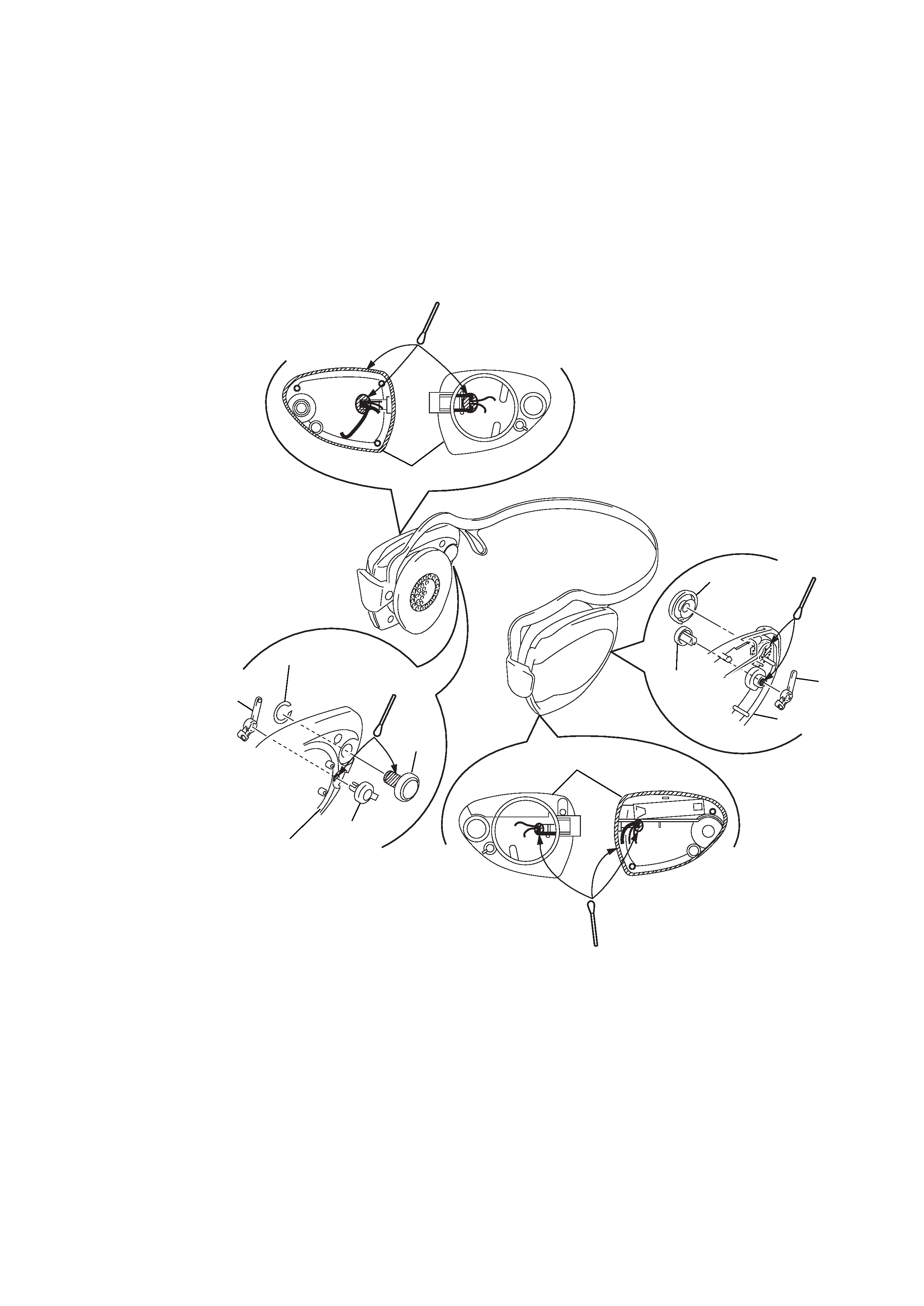
Drip-proof freatment
Be sure to execute the following, when the cabinet is removed
during service.
Applicator SONY Grease SGL-601 (7-651-000-10) and apply
Silicone KE-490RTV (7-322-065-19) to the hatched portion
shown in figure using an applicator, etc.
KE-490RTV
SGL-601
SGL-601
KE-490RTV
Knob
(power)
Knob (VOL)
Lever
Cabinet (rear) R
Knob
(power)
Cabinet (rear) L
Cabinet (rear) R
Lever
Poly-slider Washer
Knob
(tune)
Cabinet (rear) L
4
SECTION 2
GENERAL
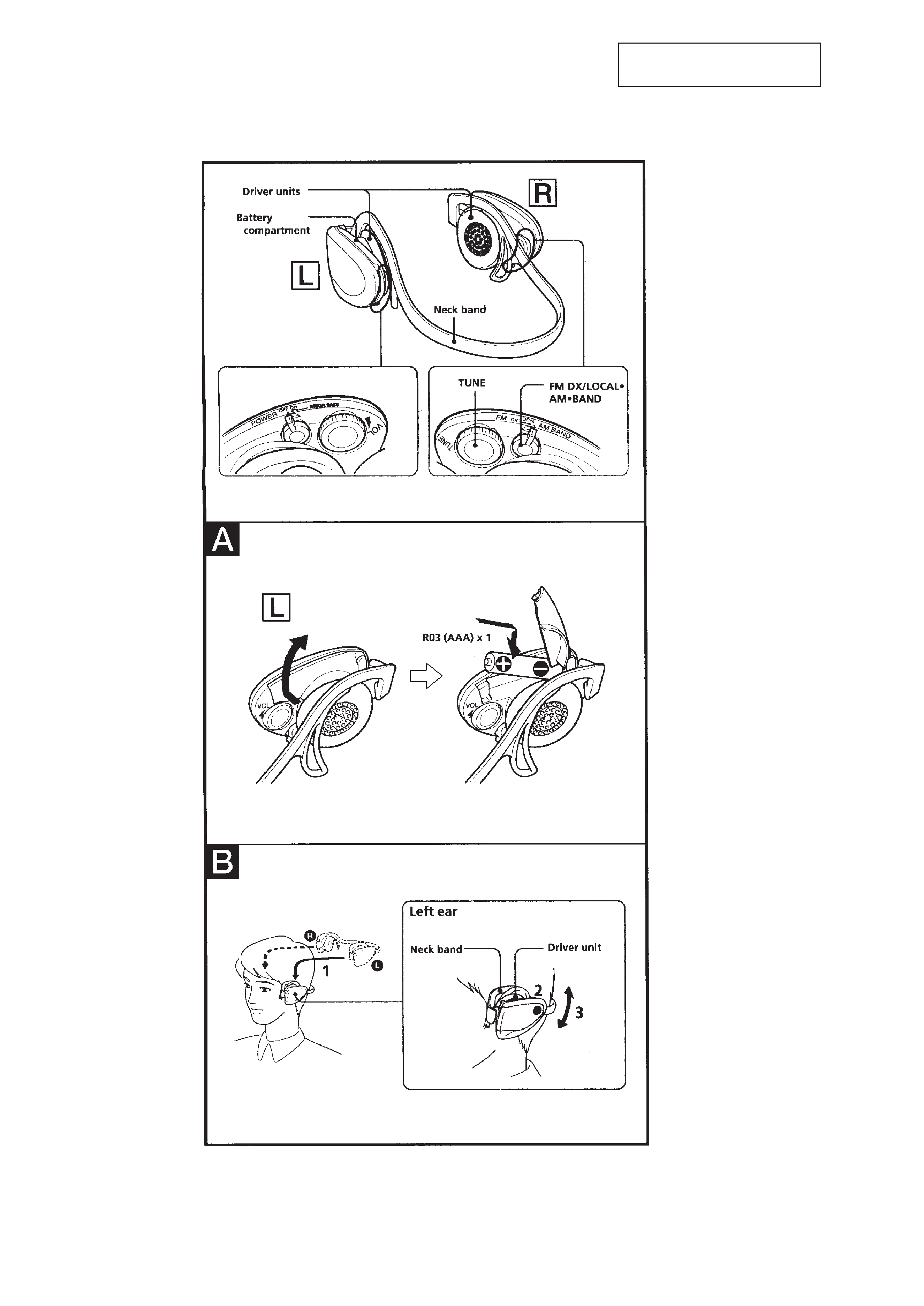
LOCATION AND FUNCTION OF CONTROLS
This section is extracted from
instruction manual.
5
SECTION 3
DISASSEMBLY
Note : Follow the disassembly procedure in the numerical order given.
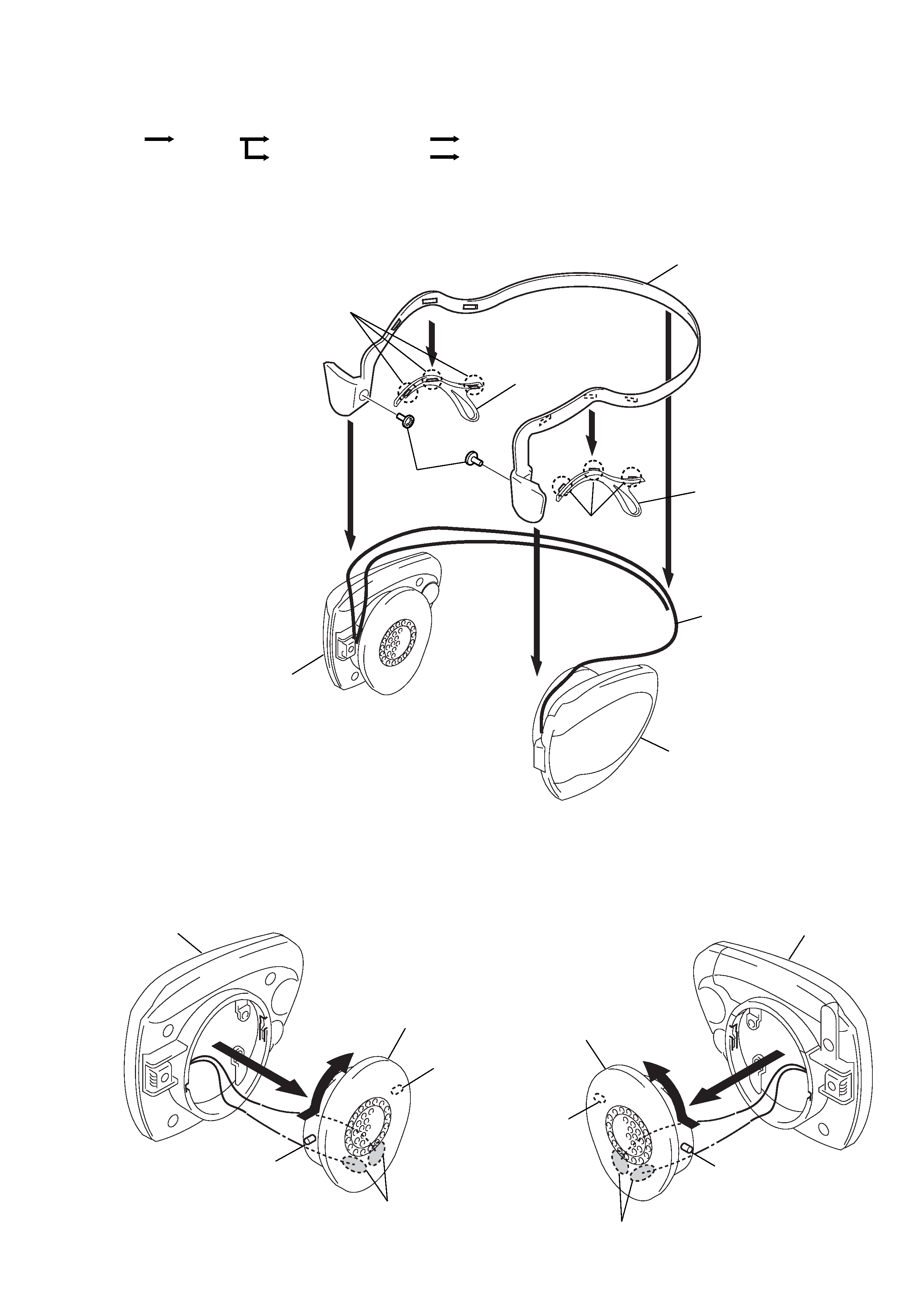
3-1. NECK BAND REMOVAL
3-2. DRIVER (HEADPHONE) (R) REMOVAL
r
The equipment can be removed using the following procedure.
3-3. DRIVER (HEADPHONE) (L) REMOVAL
1 Claws
1 Claws
3
2
5
5
2
Ear hook (R)
Ear hook (L)
Neck band
4 Screws
(+P 2x4)
Main R assy
Main L assy
Read wire
2
1
Boss
Boss
Driver (Headphone) (R)
3 Remove solder
Main R assy
2
1
Boss
Boss
Driver (Headphone) (L)
3 Remove solder
Main L assy
Neck band
Set
DRIVER (Headphone) (R)
Main board
DRIVER (Headphone) (L)
Audio board