SERVICE MANUAL
General
Spread method
Direct-Sequence Spread-Spectrum
Access method
FDMA-TDD
Frequency band
2.4075 - 2.4720 GHz
Operating channel
40 channels
Dial signal
Tone, 10 PPS (pulse) selectable
Supplied accessories
Cordless handset
Power source
Rechargeable battery pack BP-T38
Battery life
Standby: Approx. 6 days
Talk:
Approx. 5 hours
Battery charging time
Approx. 12 hours
Dimensions
Approx. 2 3/8 x 6 5/8 x 1 15/16 inches (w/h/d),
antenna excluded
(approx. 58 x 166 x 48 mm)
Antenna: Approx. 2 7/8 inches
(approx. 72 mm)
Mass
Approx. 8.1 oz
(approx. 230 g), battery included
Base unit
Power source
DC 9V from AC power adaptor
AC-T46
Dimensions
Approx. 6 1/8 x 2 5/8 x 6 inches (w/h/d),
antenna excluded
(approx. 154 x 65 x 151 mm)
Antenna: Approx. 4 3/ 8 inches
(approx. 108 mm)
Mass
Approx. 9.4 oz
(approx. 265 g)
Design and specifications are subject to
change without notice.
AC power adaptor (AC-T46)
Telephone line cord
Rechargeable battery pack (BP-T38)
CORDLESS TELEPHONE
US Model
Canadian Model
SPECIFICATIONS
SPP-S2720
Ver 1.1 2001.08
9-873-166-02
Sony Corporation
2001H0500-1
Personal Audio Company
C
2001.8
Shinagawa Tec Service Manual Production Group
2
SPP-S2720
TABLE OF CONTENTS
1.
SERVICING NOTES ............................................... 3
2.
GENERAL
Identifying the Parts ........................................................
6
Registering additional cordless handsets ........................ 10
3.
DISASSEMBLY
3-1. Disassembly Flow ........................................................... 12
3-2. Cabinet (Rear) ................................................................. 12
3-3. Hand Main Board ............................................................ 12
3-4. Base Cabinet (Lower) Assy, Key Main Board ............... 13
3-5. Base Main Board ............................................................. 13
4.
TEST MODE
Base Unit ......................................................................... 14
Handset ............................................................................ 16
RF Testing ....................................................................... 18
5.
ELECTRICAL ADJUSTMENTS
Base Unit ......................................................................... 20
Handset ............................................................................ 22
6.
DIAGRAMS
6-1. Block Diagram BASE UNIT Section ...................... 25
6-2. Block Diagram HANDSET Section ........................ 26
6-3. Note for Printed Wiring Boards and
Schematic Diagrams ....................................................... 27
6-4. Printed Wiring Board
BASE MAIN Board (Component Side) .................... 28
6-5. Printed Wiring Boards BASE MAIN
(Conductor Side)/KEY MAIN Boards ........................ 29
6-6. Schematic Diagram
BASE MAIN (1/3)/KEY MAIN Boards .................. 30
6-7. Schematic Diagram BASE MAIN Board (2/3) ....... 31
6-8. Schematic Diagram BASE MAIN Board (3/3) ....... 32
6-9. Printed Wiring Board HAND MAIN Board ........... 34
6-10. Schematic Diagram HAND MAIN Board (1/2) ..... 35
6-11. Schematic Diagram HAND MAIN Board (2/2) ..... 36
6-12. IC Pin Function Description ........................................... 37
7.
EXPLODED VIEWS
7-1. Hand Set .......................................................................... 43
7-2. Base Set ........................................................................... 44
8.
ELECTRICAL PARTS LIST ............................... 45
SAFETY-RELATED COMPONENT WARNING!!
COMPONENTS IDENTIFIED BY MARK 0 OR DOTTED
LINE WITH MARK 0 ON THE SCHEMATIC DIAGRAMS
AND IN THE PARTS LIST ARE CRITICAL TO SAFE
OPERATION. REPLACE THESE COMPONENTS WITH
SONY PARTS WHOSE PART NUMBERS APPEAR AS
SHOWN IN THIS MANUAL OR IN SUPPLEMENTS PUB-
LISHED BY SONY.
Notes on chip component replacement
· Never reuse a disconnected chip component.
· Notice that the minus side of a tantalum capacitor may be dam-
aged by heat.
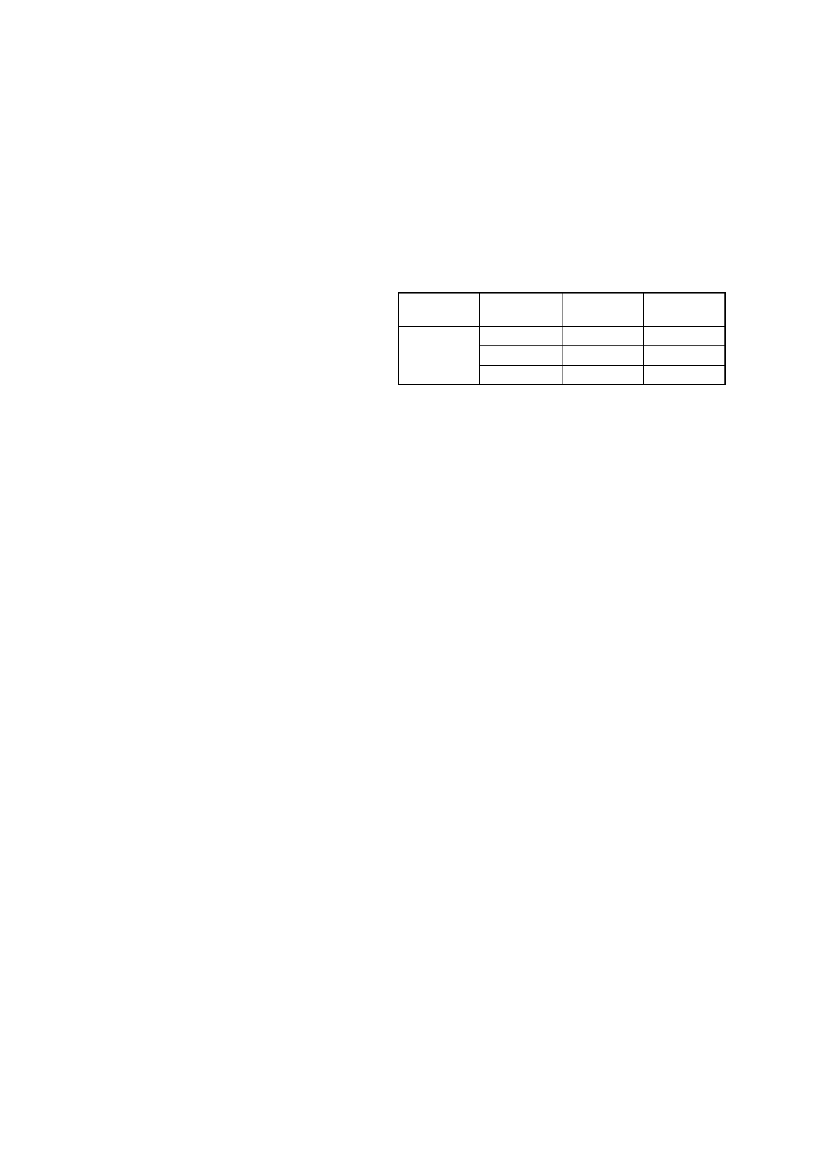
NOTE FOR REPLACEMENT OF THE CRYSTAL VI-
BRATOR ON THE HAND MAIN BOARD
There are two types of crystal vibrators used on the HAND MAIN
board. Accordingly, when replacing the crystal vibrator, replace
the following reference number parts together. Similarly, when
the following reference number parts are replaced, check which
type of crystal vibrator is used and use the same type.
Crystal
Ref. No.
TYPE A
TYPE B
vibrator
C11
18PF
33PF
X31
C12
18PF
22PF
R40
1.5k
1k
[How to identify the TYPE A or B of crystal vibrator]
The type A or B can be identified from the initial character of a
character staring indicated on the top surface of the parts.
TYPE A: Starting with a numeric value
TYPE B: Staring with alphabet D
ATTENTION AU COMPOSANT AYANT RAPPORT
À LA SÉCURITÉ!
LES COMPOSANTS IDENTIFIÉS PAR UNE MARQUE 0
SUR LES DIAGRAMMES SCHÉMATIQUES ET LA LISTE
DES PIÈCES SONT CRITIQUES POUR LA SÉCURITÉ
DE FONCTIONNEMENT. NE REMPLACER CES COM-
POSANTS QUE PAR DES PIÈCES SONY DONT LES
NUMÉROS SONT DONNÉS DANS CE MANUEL OU
DANS LES SUPPLÉMENTS PUBLIÉS PAR SONY.
Ver 1.1

3
SPP-S2720
SECTION 1
SERVICING NOTES
IF AN ERROR MESSAGE IS DISPLAYED (Handset)
If the following error message is displayed after the power was turned on, check the items where "1" is indicated.
· Note on Replacing The EEPROM
After the EEPROM was replaced, write various parameters in the "TEST MODE E" (See page 17). (For the ID, see "Writing ID Numbers"
described below)
Note: Replacing the EEPROM causes all data such as customer registered telephone directory to be cleared.
NOTE ON CONNECTING THE PANEL FOR SPP-A2780 FOR TEST MODE (Base Unit)
Some items in the test mode and electrical adjustments of this set require 12 keys for data writing, but this set does not provide 12 keys.
Accordingly, the panel (BASE CABINET (UPPER) ASSY) for the SPP-A2780 is connected for these items, but the connector CN302 for
panel connection is not mounted on the BASE MAIN board in this set.
Therefore, in performing the test mode and electrical adjustments, the connector CN302 must be additionally mounted, and it need not be
removed after use, as the patterns of the board could be damaged when removing the connector. However, note that it may be a little
difficult to close the cabinet with the CN302 left mounted because of a narrow internal space.
Further, additional mounting of the CN301 for the SPP-2780 panel connection besides the CN302 enables the LCD display. Also, in this
case, the CN301 need not be removed after repair.
RE-REGISTERING ALREADY REGISTERED SET
Initialize the registered information on base unit and all handsets, and then register again all handsets starting with handset 1 by the
method given below. When re-registering the handset, refer to "Registering additional cordless handsets" in the instruction manual. (see
page 10)
Base unit
1. Turn the power on.
2. Press three keys of [1], [EZ ACCESS], and [INTERCOM] simultaneously to set the test mode.
Handset
1. Turn the power on.
2. Press three keys of [1], [EZ ACCESS], and [INTERCOM] simultaneously.
WRITING ID NUMBERS (for additional handsets)
The ID numbers are given in decimal notation on the bottom of base unit. If handsets are added, ID can be written in the TEST mode, but
the TEST mode handles ID numbers in hexadecimal notation, thus requiring decimal numbers to be converted into hexadecimal numbers.
Accordingly, when adding the handsets, refer to "Registering additional cordless handsets" in the instruction manual. (see page 10)
However, if the EEPROM was replaced, the handsets cannot be registered by the method mentioned above. In such a case, enter various
parameters except ID numbers in the "TEST MODE E", and then register the handsets by the method given in the instruction manual.
Also, the ID numbers can be written in the "TEST MODE B"(decimal number) (base unit: see page 15, handset: see page 17).
ERROR=[]000[][]00
EEPROM (IC122) data error t Write correct data to the EEPROM.
ID error
t Write correct ID data.
EEPROM (IC122) error
t Check the EEPROM and its peripheral circuits.
4
SPP-S2720
EASY CHECK MODE (Base unit only)
This mode is simple mode for easy check. For detail confirmation, execute the test mode. (Refer to "4. TEST MODE" on page 14)
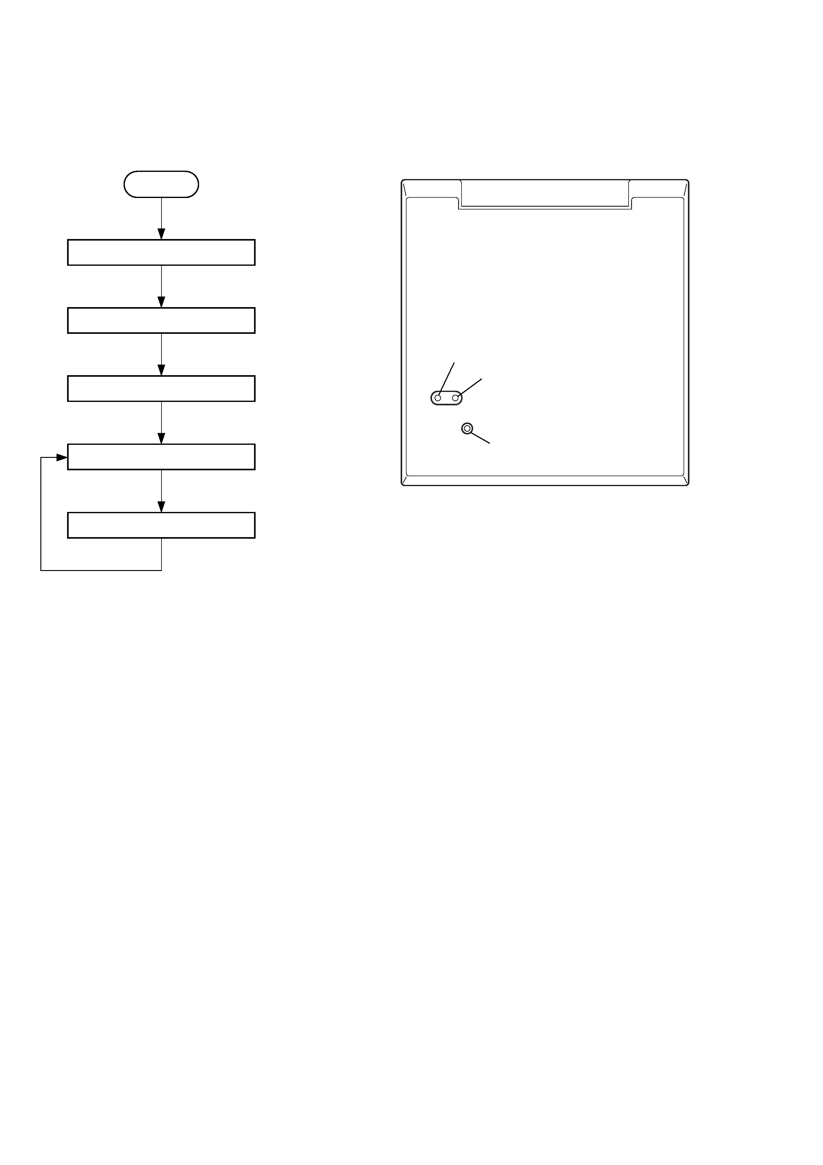
Easy check mode flow:
[SETTING]
1.
Entering The Easy Check Mode
Procedure:
1. Turn the power on.
2. While shorting the TP327 and TP335 with something like tweezers, press the [RESET] button on the bottom of the base unit with the
tip of a pen or same other sharp instrument.
3. When enter the easy check mode, it works following operations.
· Lights up the all LEDs except the [CHARGE] LED.
· Closes the line and output the dial pulse 0 one second later.
2.
Releasing The Easy Check Mode
Disconnect the power.
[CHECKING]
1.
LED Check
Procedure:
1. When enter the easy check mode, it enters the LED Check mode automatically and goes off the all LEDs in due order as [IN USE]
[NEW CALL]
[VOICE MAIL].
2. Next, it enters the line check mode automatically and opens the line.
2.
Line Check
Note: In this mode, when [HANDSET LOCATOR] key is pressed, output the dial pulse 1 to the line substitute for key touch-tone.
Procedure:
1. Connect this set and another telephone in parallel to one telephone line.
2. Call this set, and check that the [IN USE] LED lights up.
3. Take up the local handset on another telephone, and check that the [NEW CALL] LED lights up.
4. To shift the next step (Busy Tone Detection Check), press the [HANDSET LOCATOR] key.
3.
Busy Tone Detection Check
Procedure:
1. Input the busy tone from the line.
2. Check that the [VOICE MAIL] LED lights up.
3. To shift the next step (Automatic Hold Canceling Check), press the [HANDSET LOCATOR] key.
START
1. LED check
Automatic shift
2. Line check
Press the
[HANDSET LOCATOR] key
Press the
[HANDSET LOCATOR] key
3. Busy tone detection check
4. Automatic hold canceling check
Press the
[HANDSET LOCATOR] key
three times
Press the
[HANDSET LOCATOR] key
three times
5. Continuously receiving check
TP327
TP335
RESET button
SET BOTTOM VIEW
Setting Location:
Ver 1.1
5
SPP-S2720
4.
Automatic Hold Canceling Check
Note: In this mode, this set is operating as follow.
· When [HANDSET LOCATOR] key is pressed, outputs the dial pulse 1 to the line substitute for key touch-tone.
· Close the line.
· Outputs single carrier (initial channel is 5ch) to antenna.
Procedure:
1. Take up the local handset on another telephone, and check that the [IN USE] LED lights up.
2. To shift the next step (Continuously Receiving Check), press the [HANDSET LOCATOR] key three times. (Each time the
[HANDSET LOCATOR] key is pressed once, it switches the channel as 5ch
28ch 50ch)
5.
Continuously Receiving Check
Note: In this mode, this set is operating as follow.
· When [HANDSET LOCATOR] key is pressed, outputs the dial pulse 2 to the line substitute for key touch-tone.
· Close the line.
Procedure:
1. Prepare the handset, and turn the power on.
2. Press three keys of [2], [6], and [ERASE] on the handset simultaneously to enter the test mode.
3. Press the [4] key on the handset to activate the test mode D. (TX on, slave mode)
4. Press the [1] or [3] key on the handset to change the channel to 5ch. ([1] key: lowers the channel, [3] key: raises the channel)
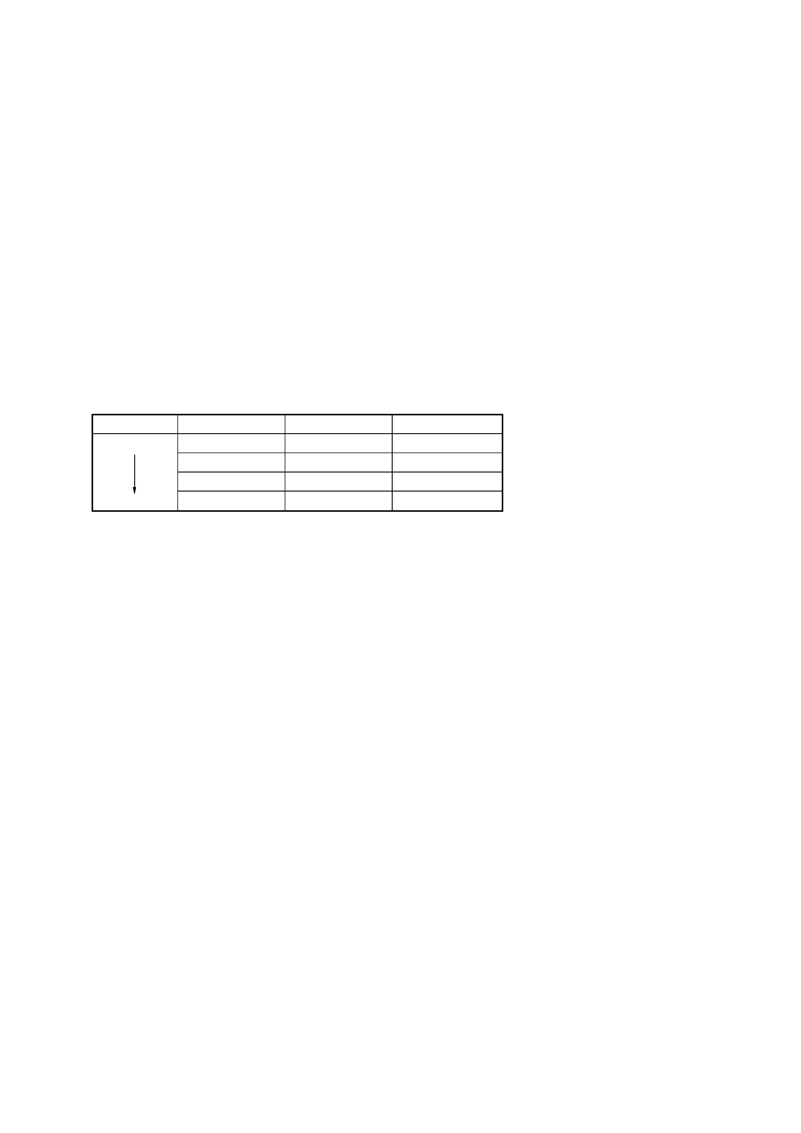
5. Indicate the link condition (4 steps) by two LEDs of [IN USE] and [NEW CALL] as follows.
*) LQM: Link Quality Monitor
6. To change the channel of base unit, press the [HANDSET LOCATOR] key. Each time the [HANDSET LOCATOR] key is pressed, it
switches the channel as 5ch
28ch 50ch.
If press the [HANDSET LOCATOR] key once more, return to step 4 (Automatic Hold Canceling Check).
EASY CLEARING THE EEPROM MODE (Base unit only)
Note: When enter this mode, it works all operations automatically.
Procedure:
1. While shorting the TP327 and TP335 and pressing the[HANDSET LOCATOR] key, turn the power on.
2. When enter this mode, it start clearing the EEPROM (exclude the set upped parameters).
3
EEPROM clearing is complete, lights up all LEDs except the [CHARGE] LED.
4. To releasing this mode, disconnect the power.
Condition
[IN USE] LED
[NEW CALL] LED
Value of LQM*
NG
off
off
21h to 3Fh
off
lights on
11h to 20h
lights on
off
09h to 10h
good
lights on
lights on
00h to 08h
Ver 1.1