http://cxema.ru
SERVICE MANUAL
GLASSTRON
AEP Model
SPECIFICATIONS
PLM-A35E
9-928-144-11
Power supply
AC power adaptor: AC-PLM2
100-240 V AC, 50/60 Hz, 16 W
Output voltage 9 V, 1.3 A
Battery pack: NP-F550 (not supplied)
Power consumption
1.8 W Approx.
Operating temperature
5
°C to 35°C (41°F to 95°F)
Storage temperature
10
°C to 60°C (14°F to 140°F)
Dimensions
Display unit:
Approx. 173
× 53 × 56 mm
(Approx. 6 7/8
× 2 1/8 × 2 1/4 inches)
(w/h/d, folded up)
Power supply box:
Approx. 53
× 39 × 104 mm
(Approx. 2 1/8
× 1 9/16 × 4 1/8 inches)
(w/h/d)
not including projecting parts and
controls
Mass
Display unit: Approx. 100 g (4 oz)
Power supply box: Approx. 90 g (3.2 oz)
Video signal
PAL colour, EIA standards
Audio/video input
Special minijack
1 Vp-p, 75 ohms, unbalanced, sync
negative
S video input
4-pin mini DIN
Y: 1 Vp-p, 75 ohms, unbalanced, sync
negative
C: 0.286 Vp-p, 75 ohms, unbalanced, sync
negative
Supplied accessories
AC power adaptor AC-PLM2 (1)
Mains lead (1)
Audio/video cable (special miniplug
y
phono plug) (3 m) (1)
Audio/video cable (special miniplug
y
stereo miniplug) (0.5 m) (1)
Plug adaptors
(phono jack
y phono jack) (3)
Nose piece (black) (1)
Side piece pads (2)
Operating instructions manual (1)
Safety Instructions (1)
Warranty (1)
Design and specifications are subject to
change without notice.

http://cxema.ru
2
PLM-A35E (AEP)
Confidential
Notes on chip component replacement
· Never reuse a disconnected chip component.
· Notice that the minus side of a tantalum capacitor may be dam-
aged by heat.
Flexible Circuit Board Repairing
· Keep the temperature of the soldering iron around 270 °C dur-
ing repairing.
· Do not touch the soldering iron on the same conductor of the
circuit board (within 3 times).
· Be careful not to apply force on the conductor when soldering
or unsoldering.
SAFETY-RELATED COMPONENT WARNING!!
COMPONENTS IDENTIFIED BY MARK
0 OR DOTTED
LINE WITH MARK
0 ON THE SCHEMATIC DIAGRAMS
AND IN THE PARTS LIST ARE CRITICAL TO SAFE
OPERATION. REPLACE THESE COMPONENTS WITH
SONY PARTS WHOSE PART NUMBERS APPEAR AS
SHOWN IN THIS MANUAL OR IN SUPPLEMENTS PUB-
LISHED BY SONY.
TABLE OF CONTENTS
1.
GENERAL
Glasstron is a Brand-new Concept in
Visual Display .............................................................. 1-1
About the Glasstron ..................................................... 1-1
Locating the Parts and Controls .................................. 1-1
Connecting the Glasstron ............................................. 1-1
Wearing the Glasstron .................................................. 1-2
Using the Glasstron ...................................................... 1-3
Setting the User Lock .................................................. 1-4
Using an Optional Battery Pack .................................. 1-4
Checking the Supplied Accessories ............................. 1-5
Precautions ................................................................... 1-5
2.
DISASSEMBLY ...................................................... 2-1
3.
ELECTRICAL ADJUSTMENTS ...................... 3-1
4.
DIAGRAMS
4-1.
Block Diagram AUDIO/VIDEO Section ............. 4-1
4-2.
Block Diagram LCD Section ............................... 4-3
4-3.
Block Diagram
KEY CONTROL/POWER SUPPLY Section ....... 4-5
4-4.
Note for Printed Wiring Boards and
Schematic Diagrams .................................................... 4-7
4-5.
Printed Wiring Board YM-A01 Board ................. 4-9
4-6.
Schematic Diagram YM-A01 Board (1/2) ............ 4-11
4-7.
Schematic Diagram YM-A01 Board (2/2) ............ 4-13
4-8.
Schematic Diagram RG-A01 Board ..................... 4-16
4-9.
Printed Wiring Board RG-A01 Board .................. 4-19
4-10 Printed Wiring Board DL-A01 Board .................. 4-21
4-11. Schematic Diagram DL-A01 Board ..................... 4-23
4-12. Printed Wiring Board HP-A01 Board .................. 4-25
4-13. Schematic Diagram HP-A01 Board ...................... 4-27
4-14. Printed Wiring Board DD-A02 Board .................. 4-29
4-15. Schematic Diagram DD-A02 Board ..................... 4-31
4-16. IC Pin Function Description ........................................ 4-41
5.
EXPLODED VIEWS ............................................. 5-1
6.
ELECTRICAL PARTS LIST ............................ 6-1
http://cxema.ru
1-1
PLM-A35E (AEP)
Confidential
SECTION 1
GENERAL
This section is extracted from instruction
manual (3-868-186-31).
5-GB
Getting
Started
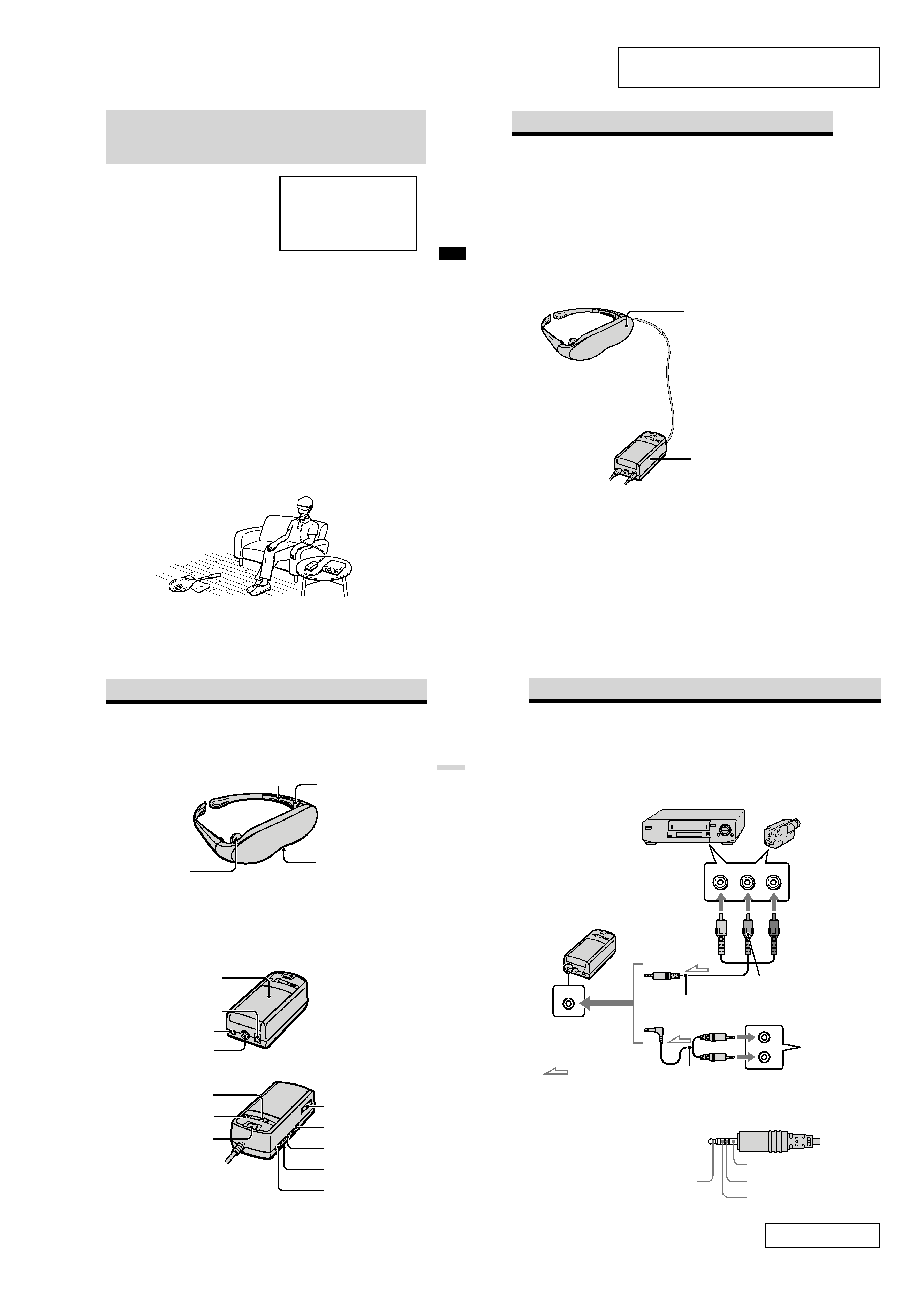
About the Glasstron
Display unit
The display unit is equipped with two
small (left and right) LCDs.
Power supply box
You can use Sony's recommended
optional battery pack. You can also use
the house current. To use the Glasstron,
connect your video equipment to A/V
IN on the power supply box.
Features
· A powerful, big screen experience
comparable to watching a 52-inch screen
from approximately 2 m (6.6 feet) away.
· Handy portable folding display.
· The display unit weighs only 100 g (4 oz).
· Approximate continuous use for up to
seven hours with Sony's recommended
battery pack, NP-F550.
Caution: The screen is always right in front of you.
The Glasstron is a face-mounted display. With this type of display, the screen is always in front
of you, even if you move your head. Because of this feature, you can concentrate on the screen
more easily compared with ordinary TVs, and you have a sense of being in the action.
· It is easy to adjust the Glasstron to your eyes. You can use the display unit even while wearing
glasses.
· Every time you use the Glasstron, the adjustment screen appears to help you adjust the
display unit properly. You can also check whether the left and right screen positions are
properly aligned or not.
· If you keep using the Glasstron continuously for three hours, a warning appears on the screen
and the power will turn off automatically.
The Glasstron consists of the following items:
3-GB
Glasstron is a brand-new concept in
visual display
Note on the LCD (Liquid Crystal
Display)
The LCD screen is made with high-
precision technology. However, black
points or bright points of light (red, blue,
or green) may appear constantly on the
LCD screen. This is not a malfunction.
(Effective dots: more than 99.99%)
Congratulations on your purchase of a Sony
Glasstron Personal Viewer. The Glasstron,
using current technology in small,
lightweight visual displays, provides a
television viewing experience similar to
watching a 52-inch television from a
distance of approximately 2 m (6.6 feet).
(Viewing experience may differ according
to individual perception.)
The Glasstron Personal Viewer creates an
image through two separate liquid crystal
displays, in close proximity to your eyes.
To insure your safe use of the Glasstron,
please become familiar with its basic
operations, including proper fitting
instructions, and be aware of any symptoms
of eye fatigue or other discomfort you may
experience.
WARNING
YOUR FAILURE TO FOLLOW THESE
OPERATING INSTRUCTIONS MAY
RESULT IN EYE FATIGUE, EYE
IMPAIRMENT, OR OTHER EYE INJURY,
PROPERTY DAMAGE OR DEATH.
WARNING
THIS PRODUCT SHOULD NOT BE USED
BY CHILDREN AGE 15 OR YOUNGER.
THE EYES OF CHILDREN ARE STILL
DEVELOPING AND MAY BE ADVERSELY
AFFECTED FROM USE OF THIS
PRODUCT.
GB
7-GB
Getting
Started
Earphone (14)
VOL (volume) control (17)
Locating the parts and controls
Refer to the pages indicated in parentheses ( ) for details.
Display unit
Power supply box
DC IN 9V connector (11)
A/V IN (audio/video) jack
(8, 9)
POWER lamp (15)
POWER ON/OFF switch (15)
BATT/COVER RELEASE
button (20)
Side piece (12)
Side piece
adjuster (13)
Nose piece (12)
BRIGHT (brightness)
control (17)
AVLS ON/OFF switch (18)
User lock switch (19)
START/BATT CHECK button
(16, 21)
S VIDEO IN jack (10)
Cover (20)
8-GB
Connecting the Glasstron
Connecting video equipment
Connect a VCR, laser disc player, DVD player, or camcorder to the power supply box as shown
below. Two AV cables are supplied. Select the correct AV cable according to the shape of the
connectors on the unit to be connected.
About the audio/video input jack
The audio/video input jack of the Glasstron is a
special minijack, and the signal connections are
aligned as shown on the right. This alignment
may differ depending on the equipment.
Audio L
GND
Video
Audio R
A/V IN
to A/V IN
(special minijack)
VCR, laser disc player, DVD player, camcorder, etc.
to audio/video outputs
(phono jack)
Video
(yellow)
Audio L
(white)
Audio R
(red)
Audio/video cable (special
miniplug
y stereo miniplug)
(supplied)
Power supply box
: Signal flow
Audio/video cable
(special miniplug
y phono
plug) (supplied)
DVD player,
Video CD
player
Video (yellow)
Audio (black)
to audio output
(stereo minijack)
to video output
(minijack)
http://cxema.ru
1-2
PLM-A35E (AEP)
Confidential
9-GB
Getting
Started
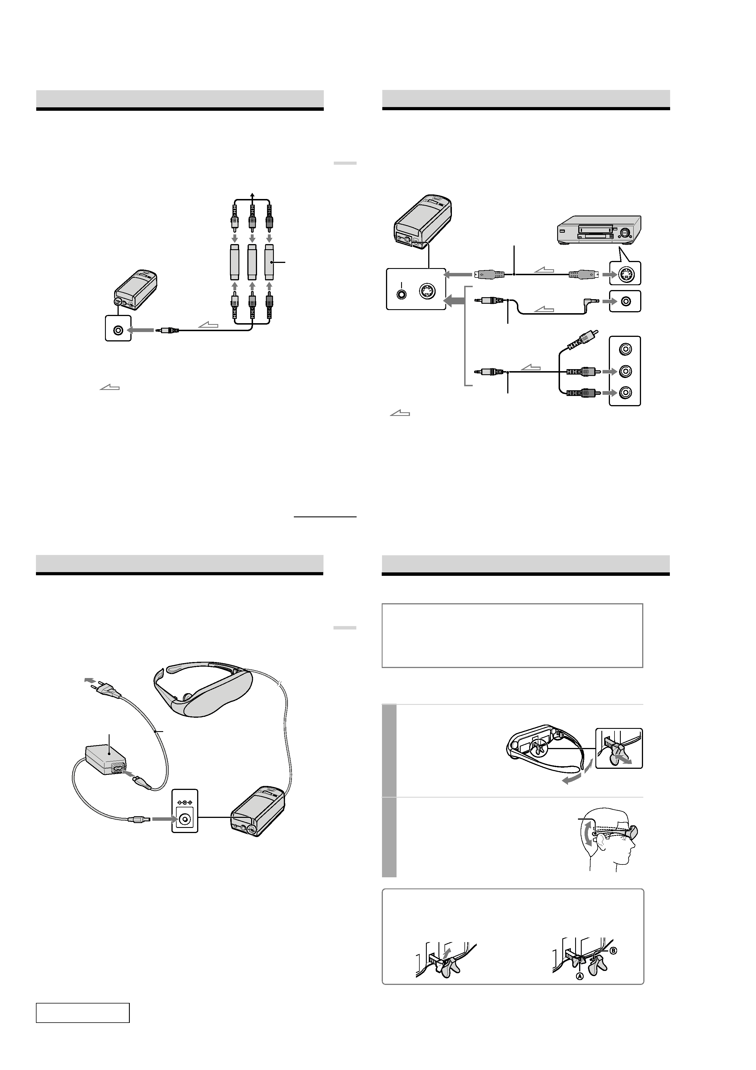
Connecting other equipment
The plug adaptor (phono jack
y phono jack) is supplied. Use the plug adaptor according to the
equipment you want to connect.
A/V IN
to A/V IN
(special minijack)
Plug adaptor
(supplied)
TV game, DVD player, camcorder, etc.
continued
: Signal flow
Audio/video cable
(special miniplug
y phono plug)
(supplied)
10-GB
Connecting the Glasstron (continued)
A/V IN
S VIDEO IN
If your video equipment has an S video jack
We recommend connecting the Glasstron to your video equipment using an S video cable and the
audio/video cable to enjoy the highest quality pictures. In this case, you do not need to connect the
video (yellow) plug. If you connect both the S video and video plugs, the S video signal is
automatically selected.
VCR, laser disc player, DVD player,
camcorder, etc.
S video cable
(not supplied)
Audio/video cable
(special miniplug
y special
miniplug) (not supplied)
Power supply box
Audio R (red)
Audio L (white)
to audio/video outputs
to A/V IN
to S VIDEO IN
to S video output
to audio/video output
Video (yellow)
Audio/video cable
(special miniplug
y phono plug)
(supplied)
: Signal flow
Notes
· Even if you use the supplied audio/video
cable, the audio and video signals may not be
carried to the Glasstron depending on the
video source. In this case, contact your Sony
dealer or local authorized Sony service
facility.
· When you connect the Glasstron to the audio
output jacks (phono jacks) of your video
equipment, connect the Glasstron to both the
right and left audio output jacks. If you
connect the Glasstron to just one audio output
jack, you will hear sound from only one of the
stereo earphones.
11-GB
Getting
Started
DC IN 9V
Display unit
AC power adaptor
AC-PLM2 (supplied)
to mains
Power supply box
to DC IN 9V
Connecting the power source
Connect the AC power adaptor AC-PLM2 (supplied) to mains. Do not connect the power source
until all other connections are complete.
Mains lead
(supplied)
12-GB
Wearing the Glasstron
WARNING
· Failure to properly fit the product (see "Proper Fit," page 5 on the Safety Instructions) each
time may result in eye fatigue, eye damage, or loss of visual functions and may result in
accident or injury.
· This product should not be used by children age 15 or younger.
The eyes of children are still developing and may be adversely affected by use of this
product, and it may cause eye fatigue, eye damage, or loss of visual functions.
In addition, this product may not be adjusted to fit a child's head.
If you normally wear glasses while watching TV, you can use the Glasstron while wearing
glasses. When you take the Glasstron off, be careful that your regular glasses not get caught on
the Glasstron.
1 Adjust the nose piece and put on the Glasstron.
Pull out the nose piece if you wear
glasses.
Open the side pieces by grasping the
side piece tips and put on the
Glasstron.
Caution:
Be careful not to poke your eyes
with the side piece tips when
putting the Glasstron on or off.
2 Adjust the angle of the display unit.
Adjust the angle of the side pieces by
grasping the side piece tips to adjust the
display unit to the most suitable viewing
position.
You do not necessarily have to rest the
side pieces on your ears.
Side piece
To use the supplied nose piece
If you are still unable to have a full view of the screen or clear picture colour on the Glasstron after
performing step 2 above, replace the nose piece with the supplied nose piece (black).
2 Insert B of the supplied nose piece
(black) into the round notch A.
1 Remove the nose piece in an upward direction
while grasping the nose piece support.
Nose piece
http://cxema.ru
1-3
PLM-A35E (AEP)
Confidential
13-GB
Getting
Started
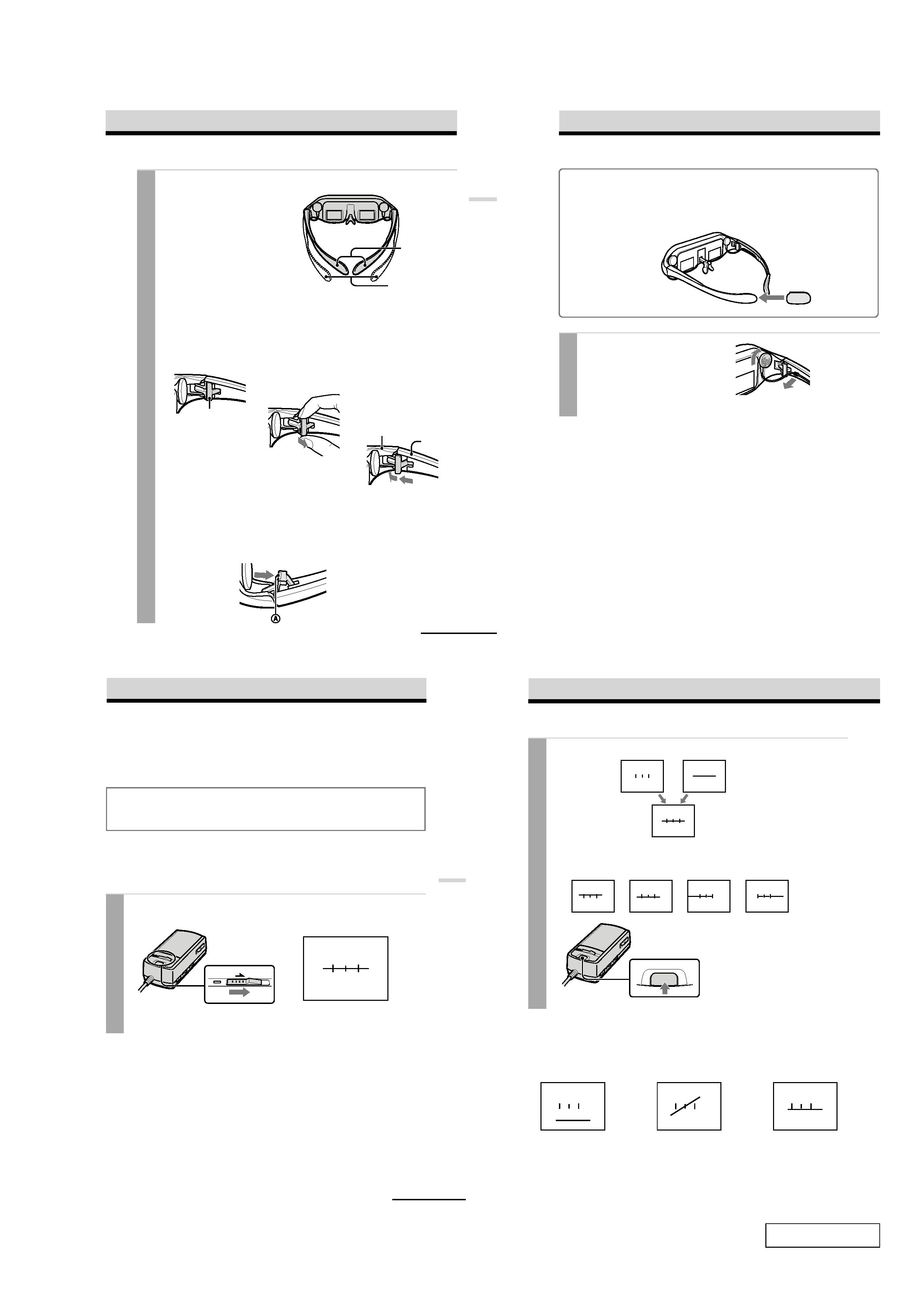
3 Adjust the width of the side pieces.
There are two settings for the side piece
width adjustment.
If the fit seems loose, insert the side
piece adjusters to the hinges of the left
and right side pieces.
To use the side piece adjusters
To reset the side piece adjusters, turn the side pieces inside slightly and reverse the
above procedure.
To put the side piece adjuster back, press A to the illustrated direction until it "clicks"
into place.
1
This is the original
position. Normally keep
adjusters here.
2
Turn the side pieces
inside slightly then
gently squeeze the top
and bottom of the side
piece adjuster and pull
out to release.
3
Slide the side piece
adjuster toward the
display unit.
4
Reinsert the side piece
adjuster tines into the
hinge area between the
side piece and display
unit. Repeat the
procedure for the other
side piece.
Using side piece
adjusters
Not using side piece
adjusters
continued
Side piece adjuster
Display unit
Side piece
3
4
14-GB
Notes
· If the stereo earphones are loose, we
recommend using the spare ear-pads (not
supplied).
· If your head is small, you may not be able to
use the Glasstron.
· Depending on your eyesight, you may not be
able to focus on the picture properly. In such
a case, it is not a malfunction.
4 Wear the stereo earphones.
Detach the stereo earphones from the
display unit and put them in your ears.
Wearing the Glasstron (continued)
For increased comfort while wearing Glasstron
If the Glasstron fit is loose or uncomfortable, place the supplied side piece pads onto the tip of each
side piece.
Note
Use the side peace pads pocket-side inward.
15-GB
Operations
Using the Glasstron
If you set the user lock, unlock it (page 19).
Before you start...
Be sure to follow the procedures in "Connecting the Glasstron" (pages 8 - 11) and "Wearing the
Glasstron" (pages 12 - 14).
WARNING
Each time you use this product, adjustment screens will appear, requiring the viewer to
properly fit the product. To prevent eye damage, do not use this product if the vertical lines
do not cross the horizontal line on the next screen.
The Glasstron includes two small (left and right) LCDs. You are watching a combined picture
created from these two screens. Although the screen position is properly aligned at the factory, it
may become misaligned if the Glasstron is deformed or damaged. Check the screen position
alignment every time you turn on the Glasstron. If you cannot have correct screen alignment,
stop using the Glasstron immediately.
1 Turn on the Glasstron using the POWER ON/OFF switch.
The POWER lamp lights up.
Screen
POWER
ON/OFF
continued
16-GB
Using the Glasstron (continued)
Left screen
Right screen
You may see a horizontal line
on the left screen rather than
the right screen and vertical
lines on the right screen
rather than the left screen.
This is not a malfunction.
The combined picture
you see with both eyes
If the image you see matches one of the pictures below, you have
correct screen alignment.
Correct
Correct
Correct
Correct
Correct
START/BATT CHECK
If the image you see matches one of the pictures
below, stop using the Glasstron immediately.
Use of the Glasstron under such conditions may cause
eye fatigue or eye damage.
When no vertical lines
cross the horizontal
line.
When the horizontal
line appears as a
diagonal line.
When the centre vertical
line does not cross the
horizontal line.
Incorrect
Incorrect
Incorrect
If you cannot see a proper arrangement of these lines even after resting your eyes for a
few hours, the Glasstron may not be operating correctly. Contact your Sony dealer or
local authorized Sony service facility.
2 If the screens are aligned, press the START/BATT CHECK button.