SPP-N1001/N1003
SERVICE MANUAL
CORDLESS TELEPHONE
SPECIFICATIONS
US Model
SPP-N1003
Canadian Model
SPP-N1001/N1003
E Model
SPP-N1001
Photo : SPP-N1003
General
Operating frequency
902-928 MHz (0.3mW)
Frequency control
Crystal-controlled PLL
Operation mode
FM, duplex
Operation channel
30 channels
Supplied accessories
AC power adaptor AC-T127
Telephone line cord
Headset TL-HD10, for the use of the left ear only (SPP-N1003)
Rechargeable battery pack BP-T50G
Directories (2 sheets)
Handset
Power source
Rechargeable battery pack BP-T50
Battery life
Standby: Approx. 30 days
Talk:
Approx. 10 hours
Dimensions
Approx. 2 1/4 x 7 1/8 x 1 15/16 inches (w/h/d), antenna excluded
(approx. 55 x 180 x 48 mm)
Antenna: Approx. 1 1/8 inches (approx. 27 mm) (SPP-N1001)
Antenna: Approx. 1 15/16 inches (approx. 48 mm) (SPP-N1003)
Mass
Approx. 5.5 oz (approx. 155 g), battery included
Base unit
Power source
DC 9V from AC power adaptor
Battery charging time
Approx. 12 hours
Dimensions
Approx. 3 7/8 x 2 1/8 x 8 3/8 inches (w/h/d)
(approx. 97 x 52 x 212 mm) (SPP-N1001)
Approx. 4 1/4 x 2 1/8 x 8 3/8 inches (w/h/d), antenna excluded
(approx. 107 x 52 x 212 mm) (SPP-N1003)
Antenna: Approx. 4 5/8 inches (approx. 115 mm) (SPP-N1003)
Mass
Approx. 7.6 oz (approx. 215 g)
Head set (TL-HD10, for the use of the left ear only) (SPP-N1003)
Cord length
Approx. 47 1/4 inches (approx. 1.2 m)
Mass
Approx. 2 oz (approx. 55 g)
Design and specifications are subjec to change without notice.
9-927-979-12
2001E0200-1
© 2001.5
Sony Corporation
Personal Audio Company
Shinagawa Tec Service Manual Production Group
Ver 1.1 2001.05
with SUPPLEMENT-1
(9-927-979-81)
2
Specifications ........................................................................... 1
1. GENERAL
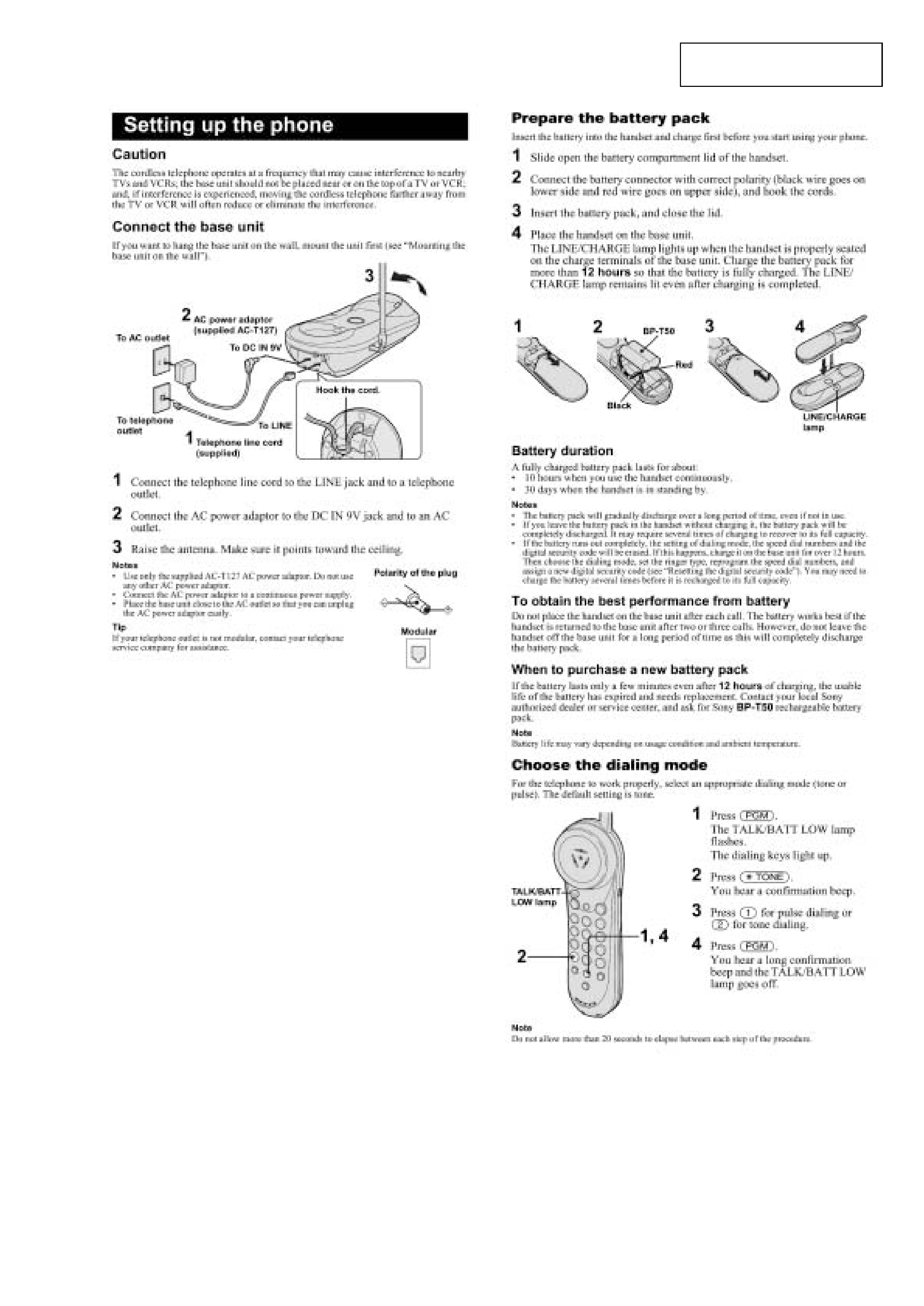
Setting up the phone .......................................................... 3
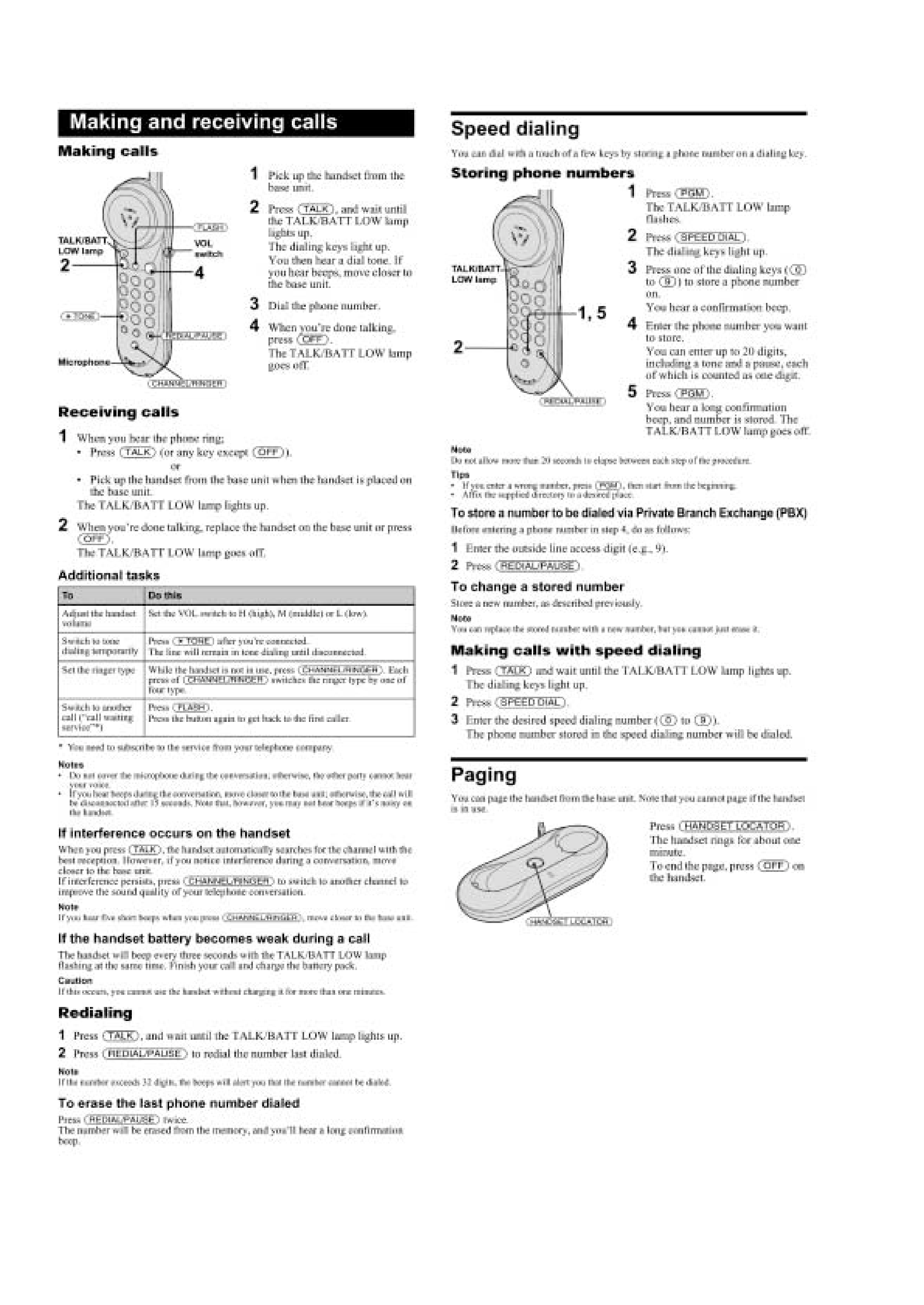
Making and Receiving calls ............................................... 4
Speed dialing ...................................................................... 4
Paging ................................................................................ 4
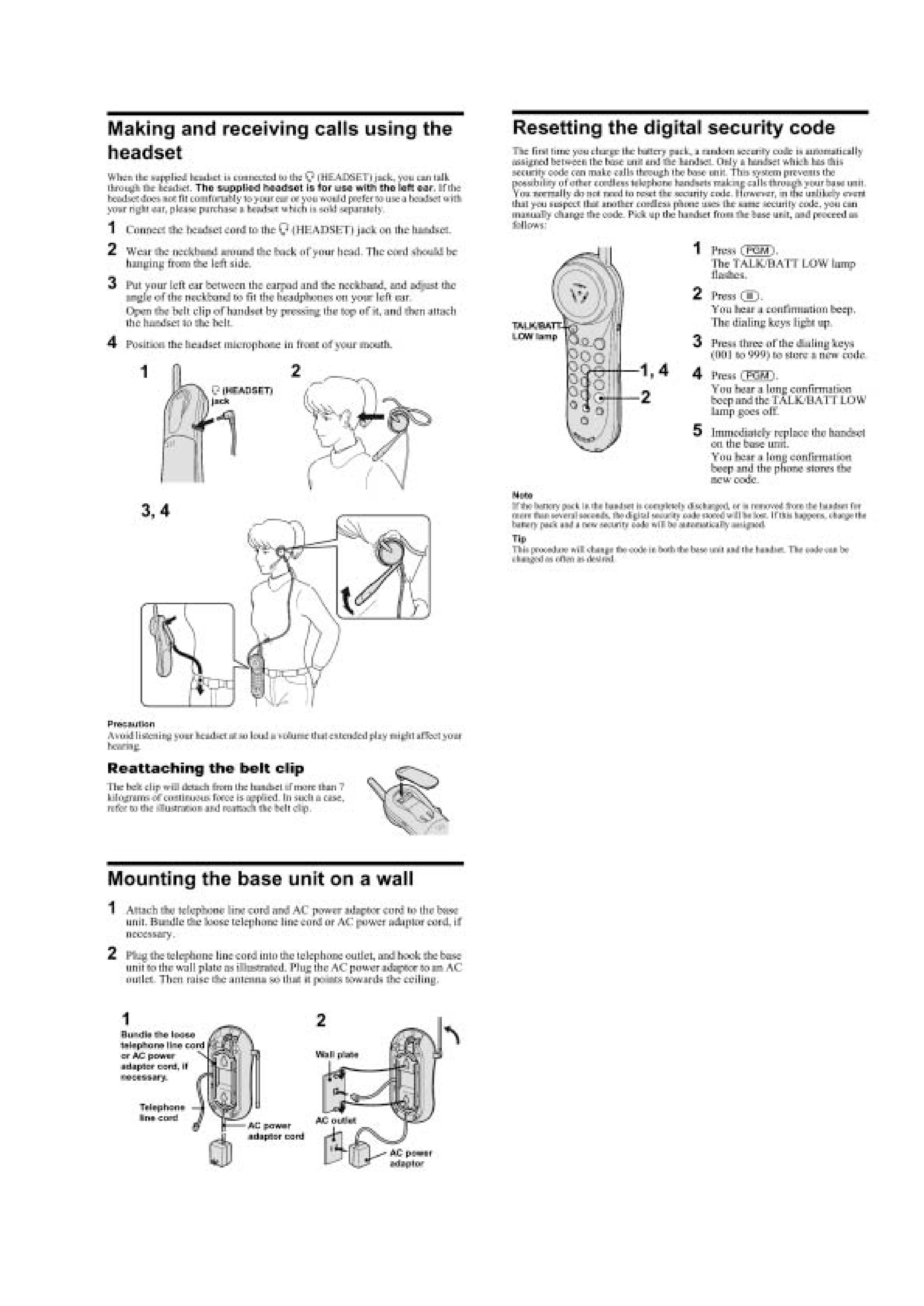
Making and Receiving calls using the
head set (SPP-N1003) ........................................................ 5
Mounting the base unit on a wall ....................................... 5
Resetting the digital security code ..................................... 5
2. DISASSEMBLY
2-1. Cabinet (Upper) .......................................................... 6
2-2. Base Main Board ........................................................ 6
2-3. Cabinet (Rear) ............................................................. 7
2-4. Jack Board (SPP-N1003 Only) ................................... 7
2-5. Hand Main Board ....................................................... 8
3. TEST MODE ................................................................... 9
4. ELECTRICAL ADJUSTMENTS
Base Unit Section .............................................................. 11
Handset section ................................................................ 13
5. DIAGRAMS
5-1. Explanation of IC Terminals ..................................... 15
5-2. Block Diagrams (Base Unit Section) ........................ 17
5-3. Block Diagrams (Handset Section) .......................... 19
5-4. Printed Wiring Boards (Base Unit Section) .............. 21
5-5. Schematic Diagram (Base Unit Section) .................. 23
5-6. Printed Wiring Boards (Handset Section) ................ 25
5-7. Schematic Diagram (Handset Section) ..................... 27
5-8. Printed Wiring Boards (Jack Section)
(SPP-N1003 Only) ................................................... 29
5-7. Schematic Diagram (Jack Section)
(SPP-N1003 Only) ................................................... 30
6. EXPLODED VIEWS
6-1. Base Unit Section ..................................................... 31
6-2. Handset Section ........................................................ 32
6-3. Head set Section (SPP-N1003 Only) ........................ 33
7. ELECTRICAL PARTS LIST .................................... 34
SAFETY-RELATED COMPONENT WARNING!!
COMPONENTS IDENTIFIED BY MARK
! OR DOTTED LINEWITH
MARK
!ON THE SCHEMATIC DIAGRAMS AND IN THE PARTS
LIST ARE CRITICAL TO SAFE OPERATION.
REPLACE THESE COMPONENTS WITH SONY PARTS WHOSE
PART NUMBERS APPEAR AS SHOWN IN THIS MANUAL OR IN
SUPPLEMENTS PUBLISHED BY SONY.
Flexible Circuit Board Repairing
· Keep the temperature of the soldering iron around 270
°C during
repairing.
· Do not touch the soldering iron on the same conductor of the
circuit board (within 3 times).
· Be careful not to apply force on the conductor when soldering or
unsoldering.
Notes on chip component replacement
· Never reuse a disconnected chip component.
· Notice that the minus side of a tantalum capacitor may be dam-
aged by heat.
TABLE OF CONTENTS
ATTENTION AU COMPOSANT AYANT RAPPORT
À LA SÉCURITÉ!
LES COMPOSANTS IDENTIFIÉS PAR UNE MARQUE
! SUR LES
DIAGRAMMES SCHÉMATIQUES ET LA LISTE DES PIÈCES SONT
CRITIQUES POUR LA SÉCURITÉ DE FONCTIONNEMENT. NE
REMPLACER CES COMPOSANTS QUE PAR DES PIÈCES SONY
DONT LES NUMÉROS SONT DONNÉS DANS CE MANUEL OU
DANS LES SUPPLÉMENTS PUBLIÉS PAR SONY.
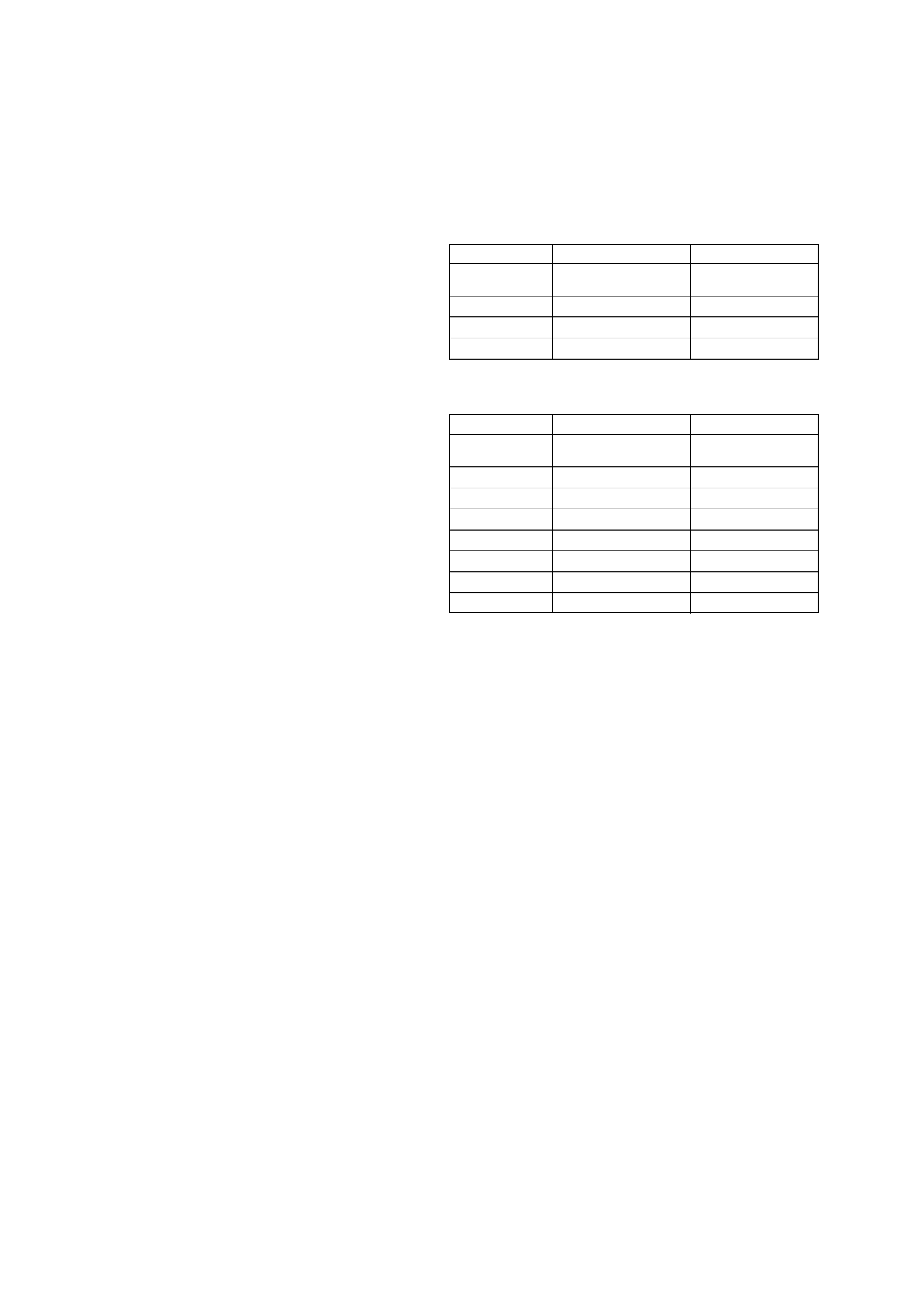
NOTE ON BASE MAIN BOARD AND HAND MAIN
BOARD REPAIR
As for base main board and hand main board, there are two type
of "A type" and "B type" by difference of diodes (D401 and
D402) used.
Difference parts list
Base main board
A type
B type
D401, D402
BB145B-115 or
1SV314 (TPH3)
HVU-355BTRF
C451
10PF
12PF
C453
4PF
6PF
C454
8PF
7PF
· D401 and D402 using same thing.
Hand main board
A type
B type
D401, D402
BB145B-115 or
1SV314 (TPH3)
HVU-355BTRF
C428
10PF
7PF
C450
10PF
12PF
C454
10PF
7PF
L405
15nH
18nH
L409
15nH
18nH
R418
10K
15K
R428
180
220
· D401 and D402 using same thing.
3
SECTION 1
GENERAL
This section is extracted from
instruction manual.
4
5
(SPP-N1003)