MICROFILM
SPP-M920
SPECIFICATIONS
CORDLESS TELEP0HONE
US Model
SERVICE MANUAL

2
Flexible Circuit Board Repairing
· Keep the temperature of the soldering iron around 270°C during
repairing.
· Do not touch the soldering iron on the same conductor of the
circuit board (within 3 times).
· Be careful not to apply force on the conductor when soldering or
unsoldering.
Notes on chip component replacement
· Never reuse a disconnected chip component.
· Notice that the minus side of a tantalum capacitor may be dam-
aged by heat.
TABLE OF CONTENTS
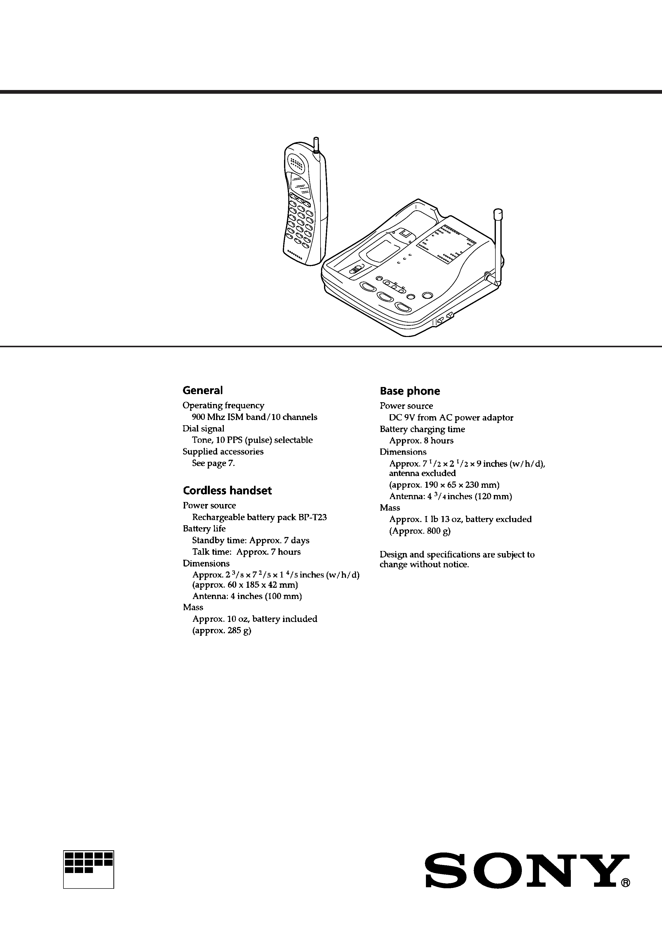
Specifications ........................................................................... 1
1.
GENERAL
Location and Function of Controls .................................... 3
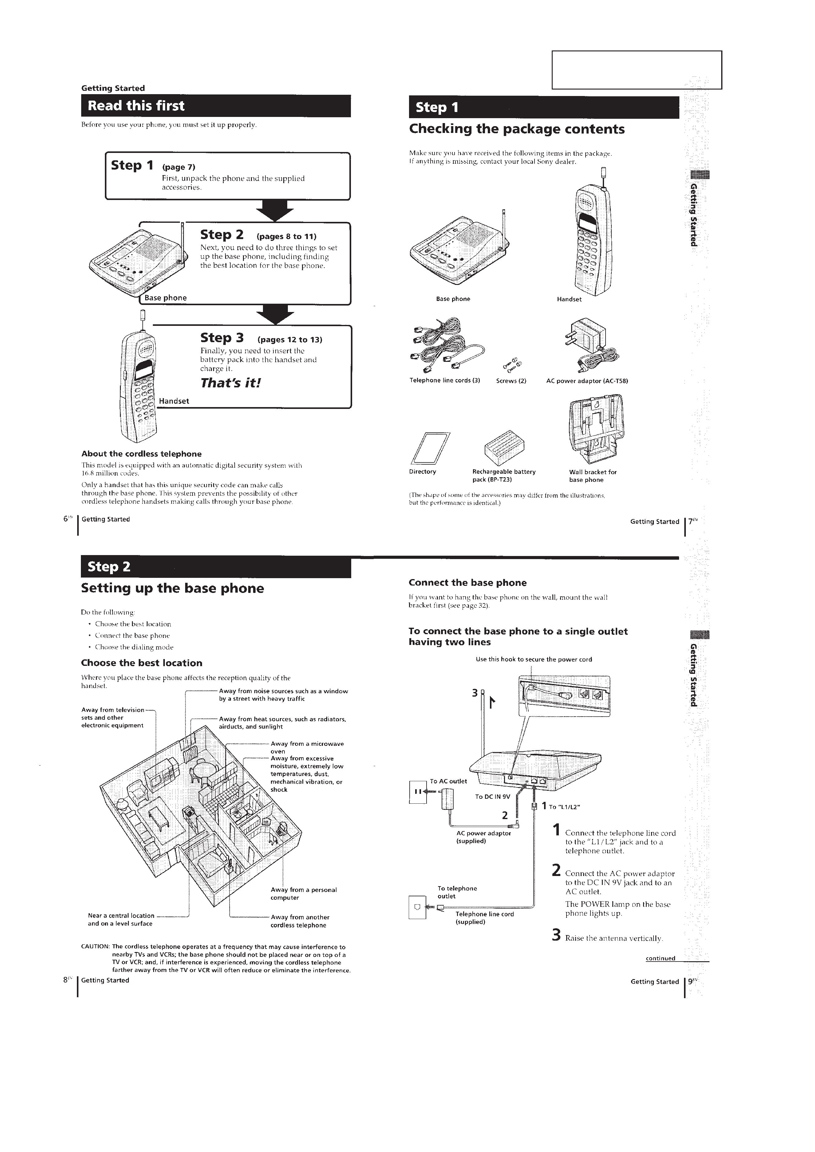
Read this first ..................................................................... 4
Step 1 : Checking the package contents ............................. 4
Step 2 : Setting up the base phone ..................................... 4
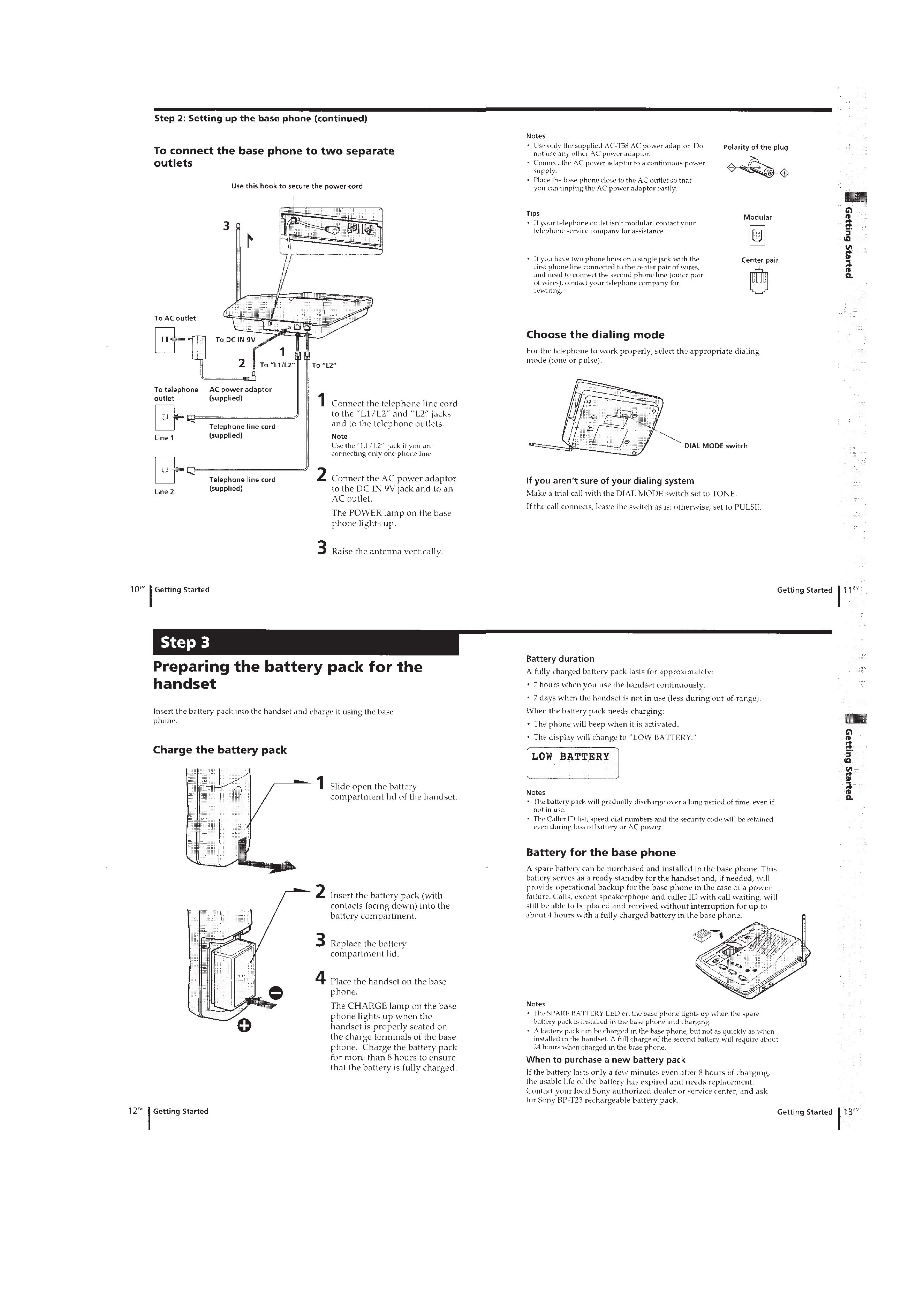
Step 3 : Preparing the battery pack for the handset ........... 5
Making calls ....................................................................... 5
Receiving calls ................................................................... 6
Changing the ringer type .................................................... 7
Speed dialing ...................................................................... 7
Talking between the phones (intercom) ............................. 8
Switching the phones durig a call ...................................... 8
Conference calls ................................................................. 8
Caller ID service ................................................................ 8
Mounting the base phone on a wall ................................. 10
Notes on power sources ................................................... 10
Maintenance ..................................................................... 10
2.
DISASSEMBLY
2-1. Battery Pack Removal ............................................... 11
2-2. Hand Cabinet (Rear) Removal .................................. 11
2-3. Antenna Removal ..................................................... 12
2-4. Hand Main Board Removal ...................................... 12
3.
CIRCUIT OPERATION ................................................. 13
4.
TEST MODE .................................................................. 19
5.
ADJUSTMENTS
5-1. Base Unit Section ..................................................... 22
5-2. Handset Section ........................................................ 24
6.
DIAGRAMS
6-1. Explanation of IC Terminals ..................................... 26
6-2. Block Diagrams ........................................................ 29
6-3. Printed Wiring Boards (Base Key Section) .............. 35
6-4. Schematic Diagram (Base Key Section) .................. 37
6-5. Schematic Diagram (Base Unit Section) .................. 42
6-6. Printed Wiring Boards (Base Unit Section) .............. 47
6-7. Printed Wiring Boards (Handset Section) ................ 52
6-8. Schematic Diagram (Handset Section) ..................... 55
7.
EXPLODED VIEWS
7-1. Base Unit Section ..................................................... 58
7-2. Handset Section ........................................................ 59
8.
ELECTRICAL PARTS LIST ........................................ 60
SAFETY-RELATED COMPONENT WARNING!!
COMPONENTS IDENTIFIED BY MARK
! OR DOTTED LINE WITH
MARK
! ON THE SCHEMATIC DIAGRAMS AND IN THE PARTS
LIST ARE CRITICAL TO SAFE OPERATION.
REPLACE THESE COMPONENTS WITH SONY PARTS WHOSE
PART NUMBERS APPEAR AS SHOWN IN THIS MANUAL OR IN
SUPPLEMENTS PUBLISHED BY SONY.
Notes when repairing/replacing the microcomputer
(Base Unit : IC8, Handset : IC11)
The microcomputer for this equipment initial used an externally
installed ROM version but incorporation of internal software (in-
ternal ROM version) led to elimination of the externally installed
ROM version.
The internal ROM version is available as a service part.
When replacing or servicing this part, the following parts must
also be replaced along with it. (only when set with the external
installed ROM version).
1. HANDSET
IC3, 4 ; Deleted (These were never available as service) parts.
R81 (10k) Deleted
R79 (10k) Added
2. BASE UNIT
IC12, 13 ; Deleted (These were never available as service) parts.
R140 (10k) Deleted
R138 (10k) Added
3
SECTION 1
GENERAL
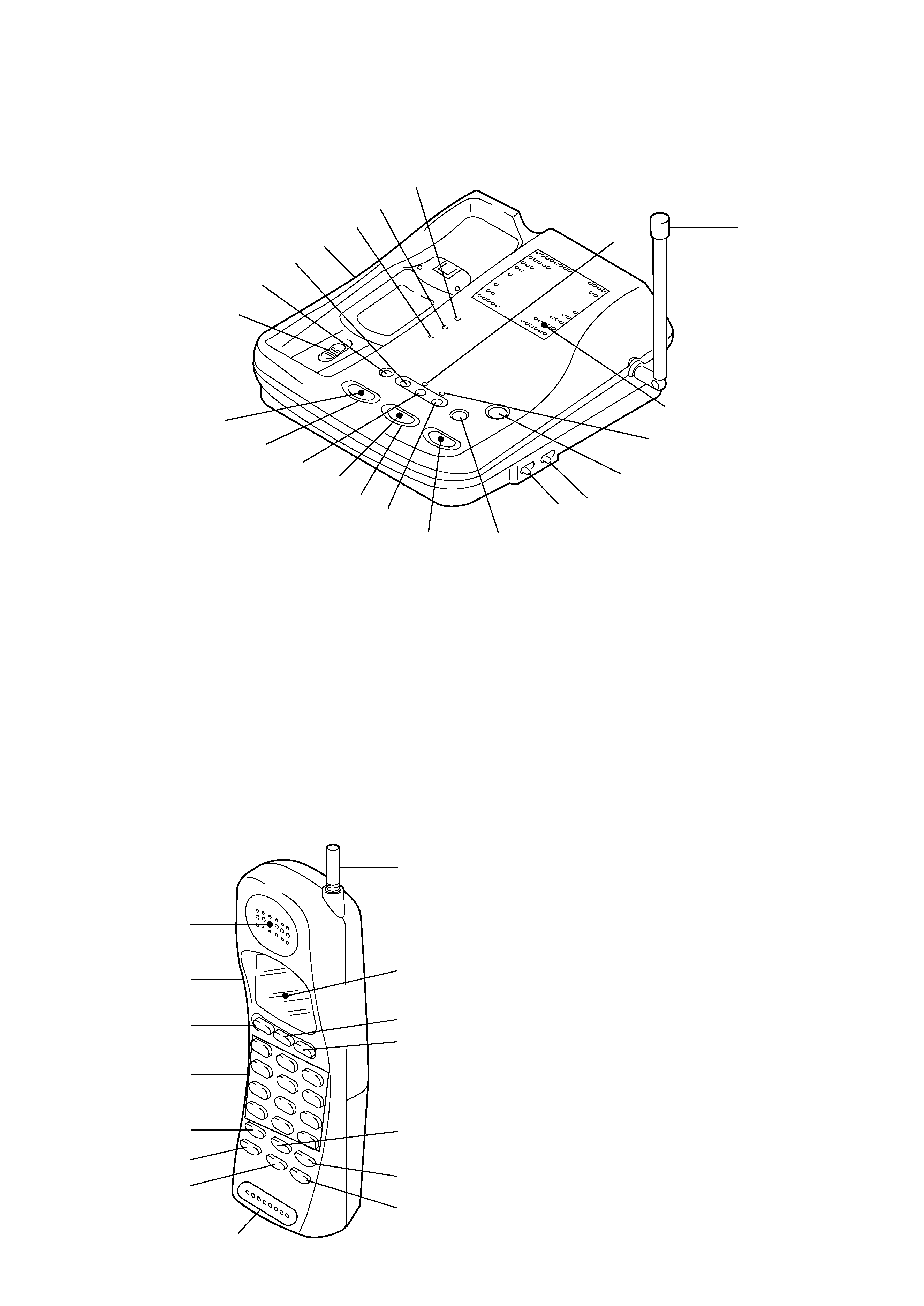
LOCATION AND FUNCTION OF CONTROLS
1 Speaker
2 VOL (Volume) +/ switch
3 LINE 1/FLASH button
4 Dialing keys
5 HOLD/PAUSE button
6 SPEED DIAL/PGM button
7 CONF/CLEAR button
8 Microphone
9 INTERCOM/DEL button
!º REDIAL button
!¡ CALLER ID button
!TM OFF button
!£ LINE 2/FLASH button
!¢ LCD panel
! Antenna
1 LINE 1 lamp
2 LINE 1/FLASH button
3 MUTE button
4 LINE 2 lamp
5 LINE 2/FLASH button
6 INTERCOM button
7 OFF button
8 VOLUME button
9 L1 RINGER ON/OFF button
!º L2 RINGER ON/OFF button
!¡ VOLUME + button
BASE UNIT
!TM INTERCOM lamp
!£ Speaker
!¢ Antenna
! MUTE lamp
!§ POWER lamp
!¶ CHARGE lamp
!· SPARE BATTERY lamp
!ª DIAL MODE (PULSE/TONE)
@º HOLD button
@¡ CONF button
@TM OPEN c (Spare Battery) knob
7
8
9 !º
!¡
!TM
!£
!¢
!
!§
!¶
!·
!ª
@º
@¡
@TM
1
2
3
4
5
6
HANDSET
7
8
!TM
!£
!¢
!
!¡
!º
9
1
2
3
4
6
5
4
This section is extracted from
instruction manual.
5