1
SERVICE MANUAL
SPECIFICATIONS
General
Dial signal
Tone, 10 PPS (pulse) selectable
Supplied accessories
See page 3.
Cordless handset
Power source
Rechargeable battery pack BP-T16
Battery life
Standby: Approx. 8 days
Talk:
Approx. 6 hours
Battery charging time
Approx. 12 hours
Dimensions
Approx. 54
× 195 × 49 mm (w/h/d),
antenna excluded
(approx. 2 1/4
× 7 3/4 × 1 15/16 inches)
Antenna: Approx. 285 mm
(approx. 11 1/4 inches)
Mass
Approx. 255 g (approx. 8 oz), battery
included
SPP-888
E Model
CORDLESS TELEPHONE
Base phone
Power source
DC 9V from AC power adaptor
Dimensions
Approx. 185
× 95 × 215 mm (w/h/d),
antenna excluded
(approx. 7 3/8
× 3 3/4 × 8 1/2 inches)
Antenna: Approx. 700 mm
(approx. 27 5/8 inches)
Mass
Approx. 755 g (approx. 27 oz)
Cordless handset charge cradle
Power source
DC 9V from AC power adaptor
Dimensions
Approx. 68
× 90 × 220 mm (w/h/d)
(approx. 2 3/4
× 3 5/8 × 8 3/4 inches)
Mass
Approx. 180 g (approx. 6 oz), wall bracket
included
Design and specifications are subject to
change without notice.
MICROFILM
Base phone
Cordless
handset

2
TABLE OF CONTENTS
SAFETY-RELATED COMPONENT WARNING!!
COMPONENTS IDENTIFIED BY MARK
! OR DOTTED LINE
WITH MARK
! ON THE SCHEMATIC DIAGRAMS AND IN
THE PARTS LIST ARE CRITICAL TO SAFE OPERATION.
REPLACE THESE COMPONENTS WITH SONY PARTS WHOSE
PART NUMBERS APPEAR AS SHOWN IN THIS MANUAL OR
IN SUPPLEMENTS PUBLISHED BY SONY.
1. GENERAL
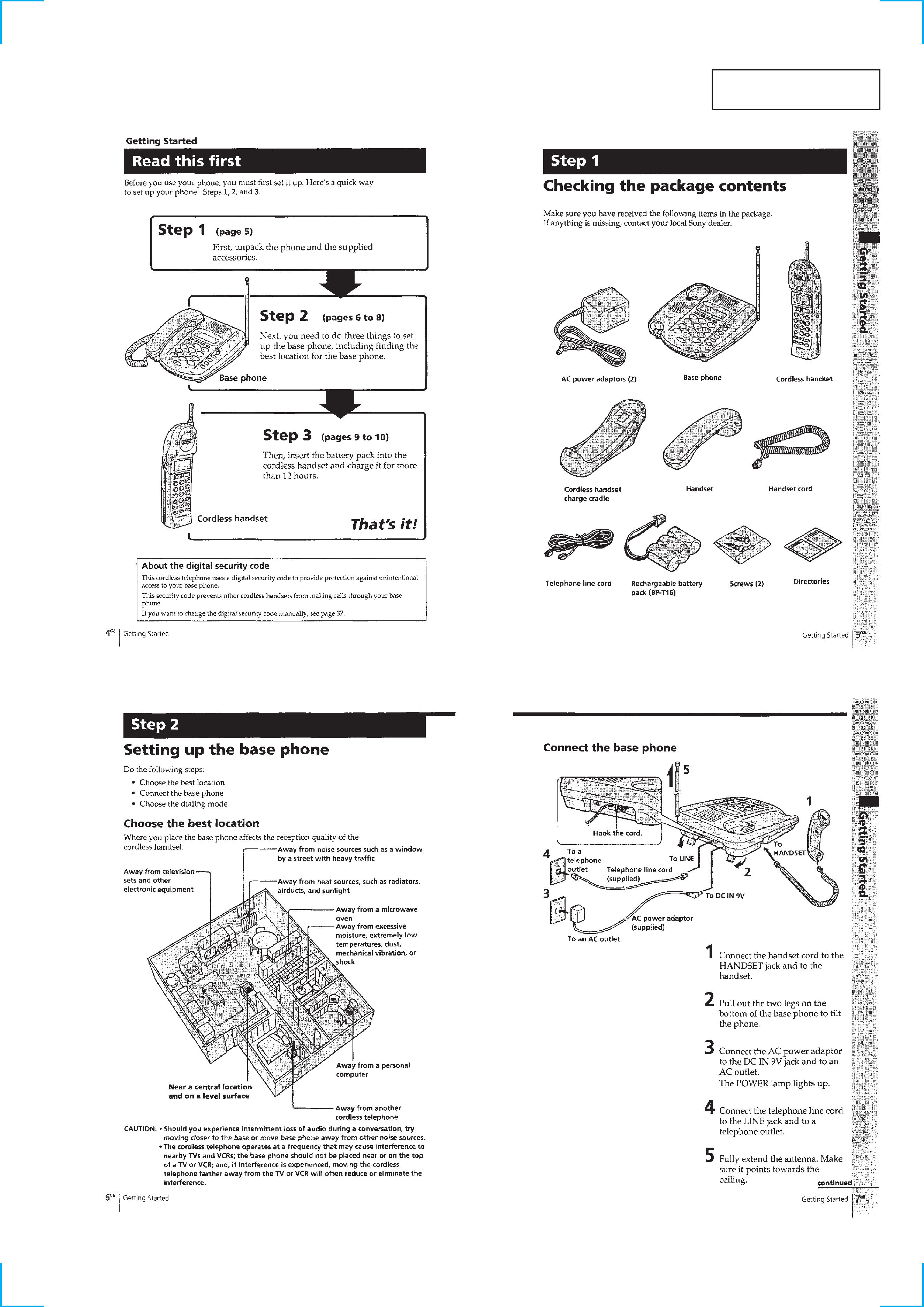
Read this first ........................................................................... 3
Checking the package contents ............................................... 3
Setting up the base phone ........................................................ 3
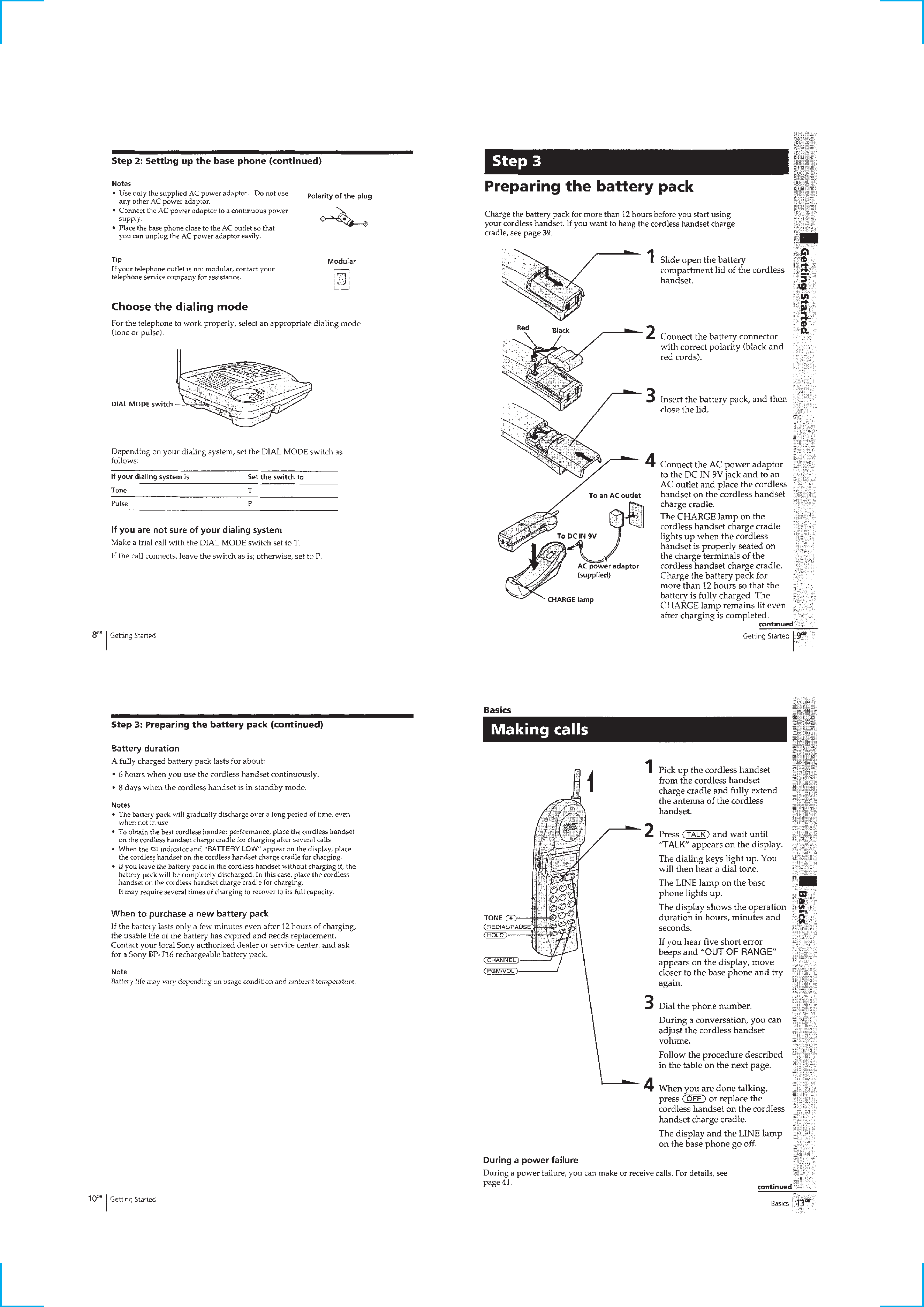
Preparing the battery pack ....................................................... 4
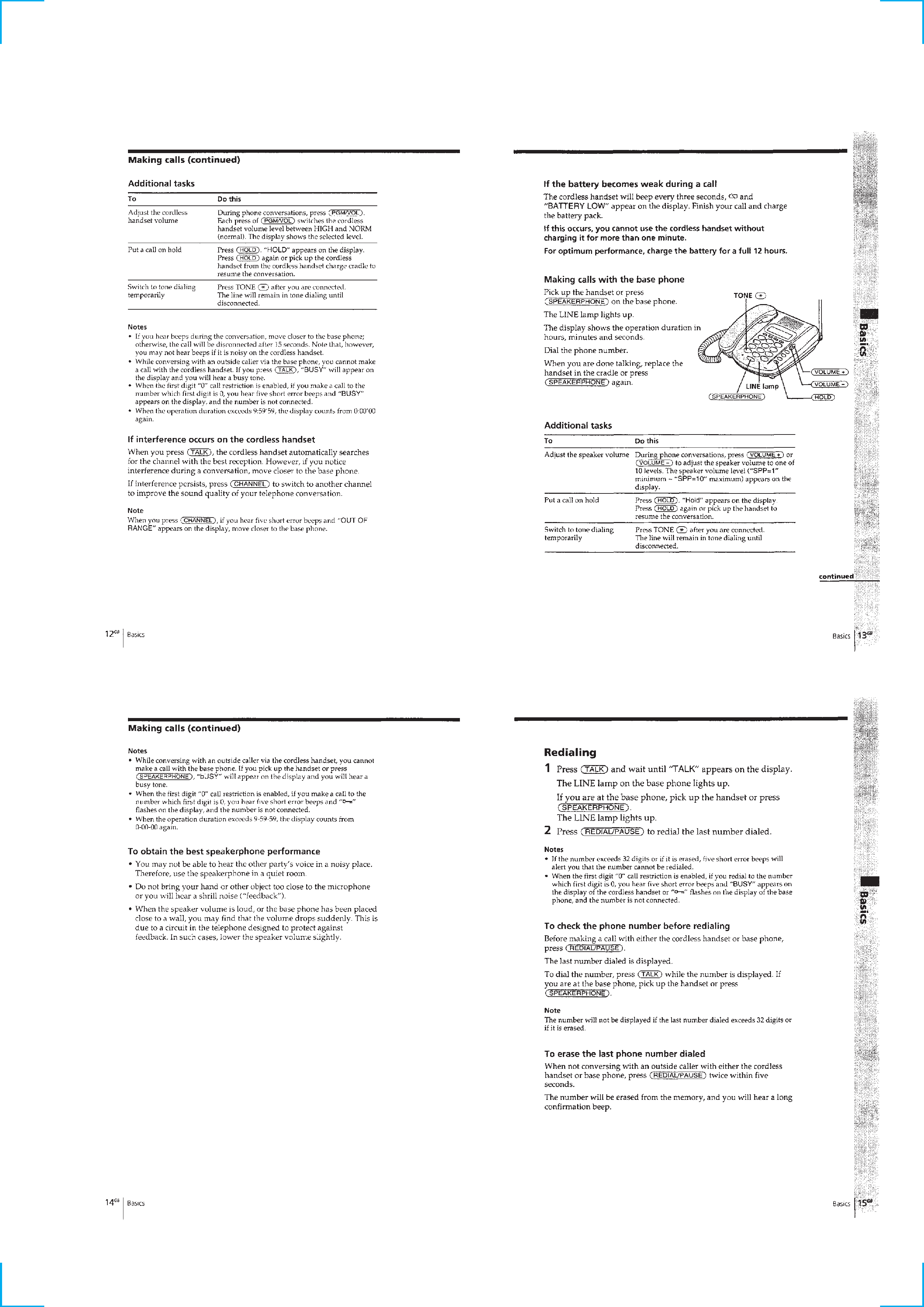
Making calls ............................................................................ 4
Receiving calls ......................................................................... 6
One-touch dialing .................................................................... 6
Speed dialing ........................................................................... 7
Phone Directory ....................................................................... 7
Switching the phones during a call .......................................... 9
Talking between the phones (Intercom) .................................. 9
Voice paging ............................................................................ 9
Transferring a call .................................................................. 10
First digit "0" call restriction ................................................. 10
Changing the digital security code ........................................ 11
Mounting the cordless handset charge cradle ........................ 11
2. DISASSEMBLY
2-1. Cabinet (Lower) ................................................................ 13
2-2. Base LCD Board ............................................................... 13
2-3. Base Key Board ................................................................. 14
2-4. Base Mic Board ................................................................. 14
2-5. Base Main Board ............................................................... 15
2-6. Cabinet (Rear) ................................................................... 15
2-7. Hand Main Board .............................................................. 16
3. TEST MODE
Base Phone Section ............................................................... 17
Handset Section ..................................................................... 19
4. ELECTRICAL ADJUSTMENTS
Base Phone Section ............................................................... 22
Handset Section ..................................................................... 24
5. DIAGRAMS
5-1. IC Pin Description ............................................................. 26
5-2. Block Diagram Base Phone Section ............................. 27
5-3. Block Diagram Handset Section ................................... 28
5-4. Printed Wiring Board Base Key Section ....................... 29
5-5. Schematic Diagram Base Key Section .......................... 29
5-6. Printed Wiring Boards Base Main Section .................... 30
5-7. Schematic Diagram Base Main (1/3) Section ............... 31
5-8. Schematic Diagram Base Main (2/3) Section ............... 32
5-9. Schematic Diagram Base Main (3/3) Section ............... 33
5-10. Printed Wiring Board Base LCD Section ...................... 34
5-11. Schematic Diagram Base LCD Section ........................ 35
5-12. Printed Wiring Board Hand Main Section .................... 36
5-13. Schematic Diagram Hand Main Section ....................... 37
5-14. Printed Wiring Board Hand Key Section ...................... 38
5-15. Schematic Diagram Hand Key Section ......................... 39
6. EXPLODED VIEWS
6-1. Base Phone Section ........................................................... 44
6-2. Handset Section ................................................................. 45
7. ELECTRICAL PARTS LIST ........................................ 46
Notes on Chip Component Replacement
· Never reuse a disconnected chip component.
· Notice that the minus side of a tantalum capacitor may be dam-
aged by heat.
3
SECTION 1
GENERAL
This section is extracted
from instruction manual.
4
5