MICROFILM
SPP-800/810/850/860
SERVICE MANUAL
CORDLESS TELEPHONE
SPECIFICATIONS
Taiwan Model
General
Frequency control
Crystal-controlled PLL
Output mode
FM, duplex
Operation channel
10 channels
Supplied accessories
AC Power adaptor AC-T56 (1)
Telephone Line cords (1)
Rechargeable battery pack BP-T16 (1)
Directories (2 sheets)
Screw (2)
Handset
Power source
Rechargeable battery pack BP-T16
Battery life
Standby : Approx. 14 days
Talk : Approx. 6 hours
Dimensions
Approx. 2 3/8 x 8 x 2 3/8 inches (w/h/d), antenna
excluded (Approx. 59 x 201 x 59mm)
Antenna : 4 3/8 inches (110mm)
Mass
Approx. 8.1 oz (Approx. 230g), battery included
Base unit
Power source
DC 9V from AC power adaptor
Battery charging time Approx. 12hours
Dimensions
Approx. 5 7/8 x 2 3/8 x 9 inches (w/h/d), antenna
excluded (Approx. 148 x 58 x 233mm)
Antenna : 17 inches (430mm)
Mass
Approx. 12.1 oz (Approx. 345g)
Design and specifications are subject to change without notice.

2
Specifications ........................................................................... 1
1. GENERAL
Location and Function of Controls .................................... 3
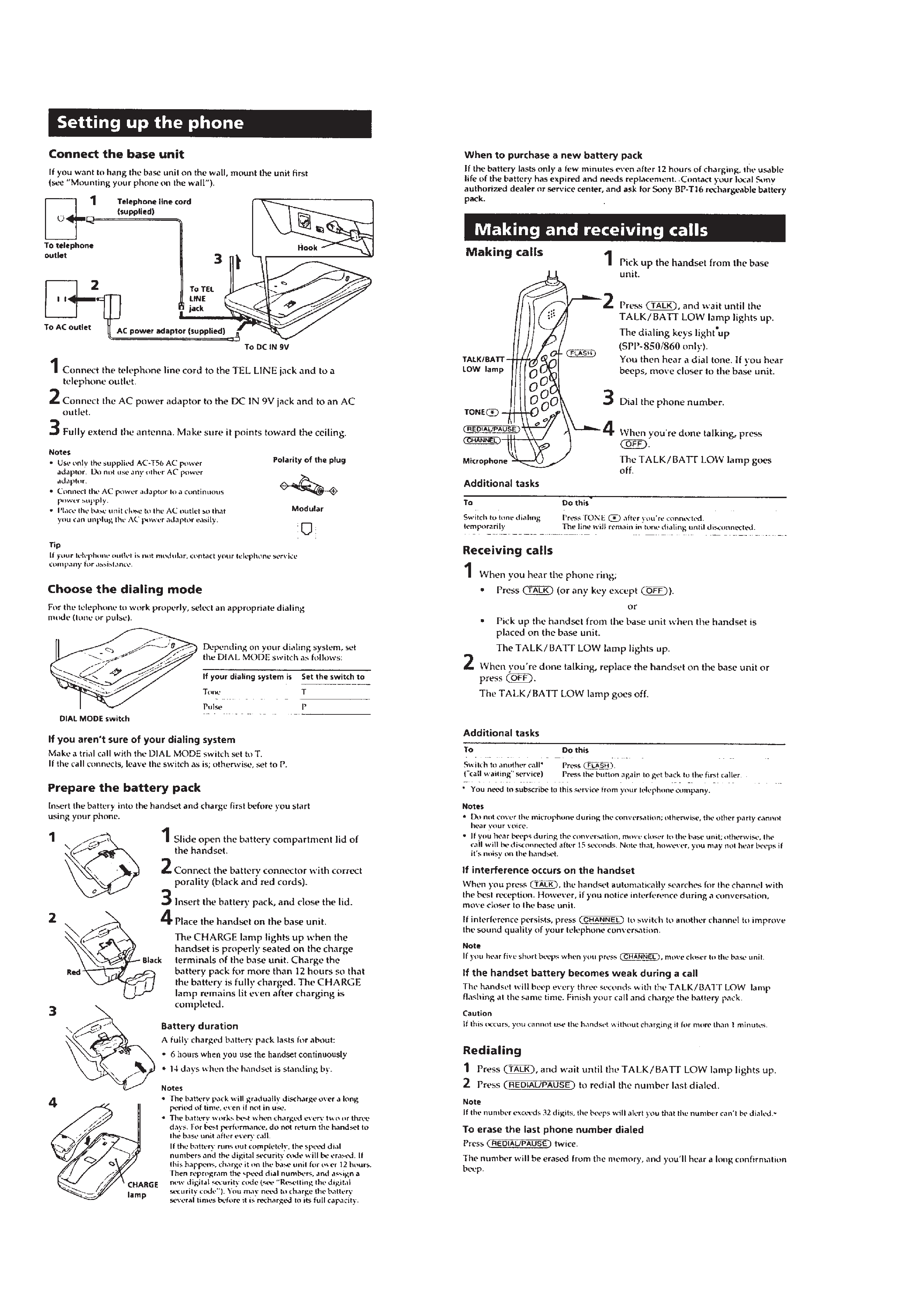
Setting up the Phone .......................................................... 4
Making and Receiving Calls .............................................. 4
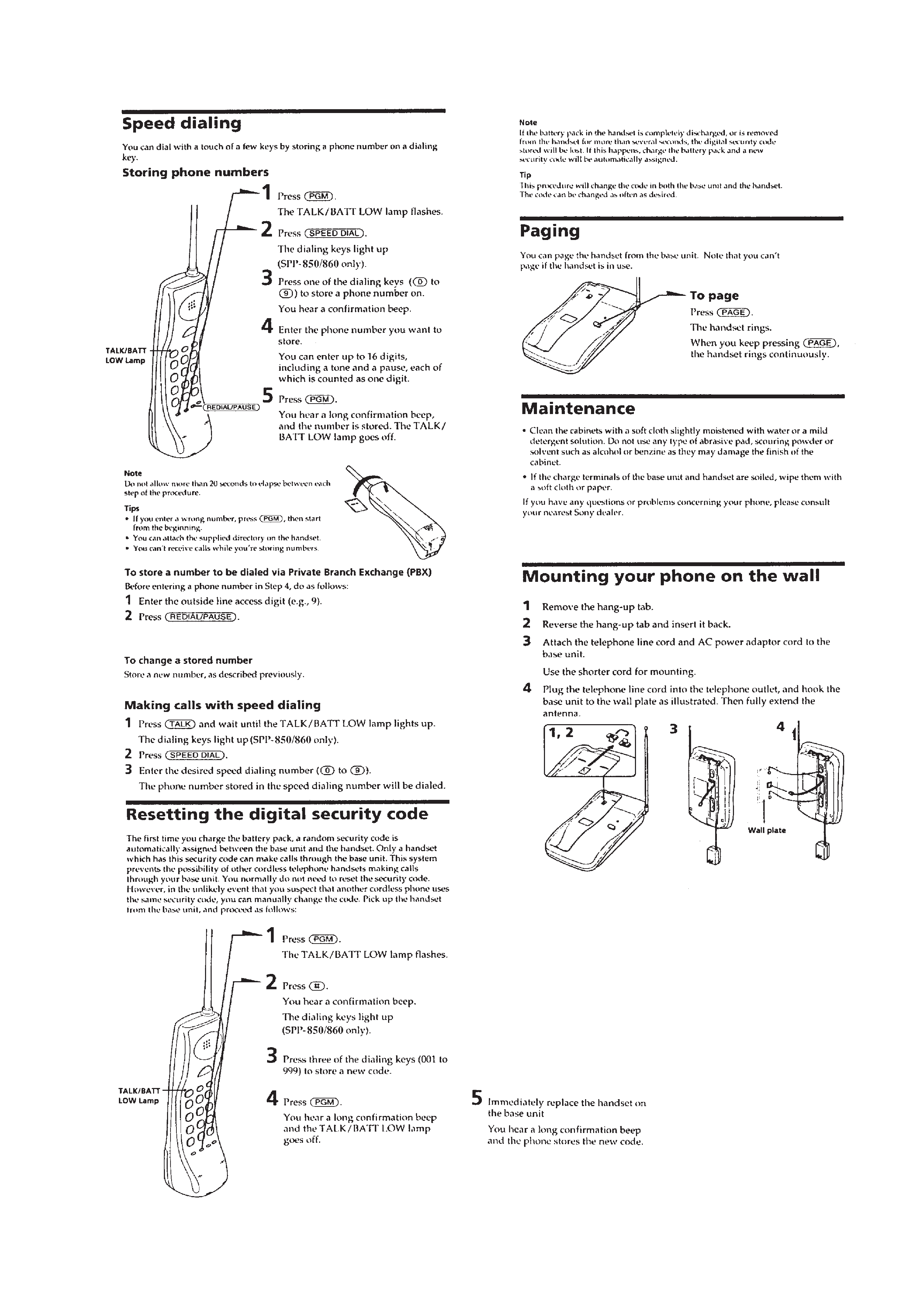
Speed Dialing ..................................................................... 5
Resetting the Digital Security Code ................................... 5
Paging ................................................................................ 5
Maintenance ....................................................................... 5
Mounting Your Phone on the Wall ..................................... 5
2. DISASSEMBLY
2-1. Battery Case Lid Removal .......................................... 6
2-2. Cabinet (Rear) Removal ............................................. 6
2-3. Hand Main Board Removal ........................................ 6
3. TEST MODE ............................................................ 7
4. ELECTRICAL ADJUSTMENTS
4-1. Base Unit Section ..................................................... 12
4-2. Handset section ......................................................... 16
5. DIAGRAMS
5-1. Explanation of IC Terminals ..................................... 20
5-2. Block Diagrams (Base Unit Section) ........................ 23
5-3. Block Diagrams (Handset Section) .......................... 25
5-4. Printed Wiring Boards (Base Unit Section) .............. 27
5-5. Schematic Diagram (Base Unit Section) .................. 29
5-6. Schematic Diagram (Handset Section) ..................... 32
5-7. Printed Wiring Boards (Handset Section) ................ 35
6. EXPLODED VIEWS
6-1. Handset Section ........................................................ 37
6-2. Base Unit Section ..................................................... 38
7. ELECTRICAL PARTS LIST ................................ 39
SAFETY-RELATED COMPONENT WARNING!!
COMPONENTS IDENTIFIED BY MARK
! OR DOTTED LINE
WITH MARK
!ON THE SCHEMATIC DIAGRAMS AND IN THE
PARTS LIST ARE CRITICAL TO SAFE OPERATION.
REPLACE THESE COMPONENTS WITH SONY PARTS WHOSE
PART NUMBERS APPEAR AS SHOWN IN THIS MANUAL OR
IN SUPPLEMENTS PUBLISHED BY SONY.
Notes on chip component replacement
· Never reuse a disconnected chip component.
· Notice that the minus side of a tantalum capacitor may be
damaged by heat.
TABLE OF CONTENTS
3
SECTION 1
GENERAL
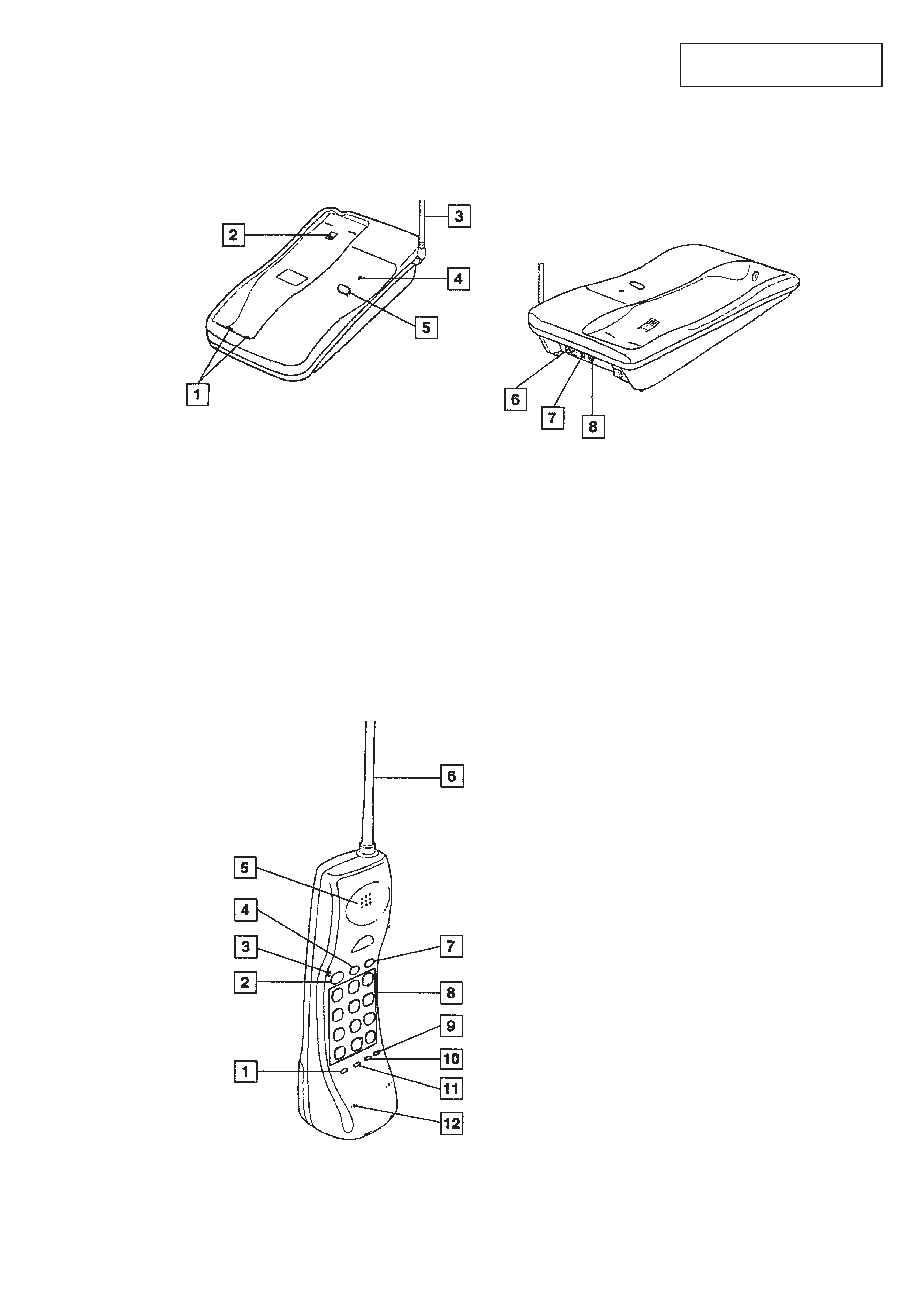
LOCATION AND FUNCTION OF CONTROLS
1 SPEED DAIAL
2 TALK button
3 TALK/BATT low lamp
4 OFF button
5 SPEAKER
6 Helical antenna
7 FLASH button
8 Dialing keys
9 CHANNEL button
!º REDIAL/PAUSE button
!¡ PGM
!TM Microphone
1 Charging terminals
2 Hang-up tab
3 Telescopic antenna
4 POWER/CHARGE/IN USE lamp
BASE UNIT
HANDSET
This section is extracted from
instruction manual.
5 PAGE key
6 LINE jack
7 DIAL MODE switch
8 DC IN 9V jack
4
5