http://cxema.ru
CHASSIS
SERVICE MANUAL
SPECIFICATIONS
CPD-G420
[with LCC]
CR1
S. Hemisphere Model
Equator Model
Chassis No. SCC-L33C-A
TRINITRON® COLOR COMPUTER DISPLAY
CRT
0.24 mm aperture grille pitch
19 inches measured diagonally
90-degree deflection
FD Trinitron
Viewable image size
Approx. 365
× 274 mm (w/h)
(143/8
× 107/8 inches)
18.0" viewing image
Resolution
Maximum
Horizontal: 1920 dots
Vertical: 1440 lines
Recommended
Horizontal: 1280 dots
Vertical: 1024 lines
Input signal levels
Video signal
Analog RGB: 0.700 Vp-p
(positive), 75
SYNC signal
H/V separate or composite sync:
TTL 2 k
, Polarity free
Sync on Green: 0.3 Vp-p
(negative)
Standard image area
Approx. 352
× 264 mm (w/h)
(137/8
× 101/2 inches)
or
Approx. 330
× 264 mm (w/h)
(13
× 101/2 inches)
Deflection frequency*
Horizontal: 30 to 110 kHz
Vertical: 48 to 170 Hz
AC input voltage/current
100 to 240 V, 50 60 Hz, 2.0 1.0 A
Power consumption
Approx. 130 W (with no USB devices
connected)
Dimensions
Approx. 451
× 471 × 461 mm (w/h/d)
(177/8
× 185/8 × 181/4 inches)
Mass
Approx. 25.5 kg (56 lb 3 oz)
Plug and Play
DDC2B/DDC2Bi, GTF**
* Recommended horizontal and vertical timing condition
· Horizontal sync width duty should be more than 4.8% of
total horizontal time or 0.8
µs, whichever is larger.
· Horizontal blanking width should be more than 2.3
µsec.
· Vertical blanking width should be more than 450
µsec.
** If the input signal is Generalized Timing Formula (GTF)
compliant, the GTF feature of the monitor will automatically
provide an optimal image for the screen.
Design and specifications are subject to change without notice.
http://cxema.ru
CPD-G420
2
LEAKAGE TEST
The AC leakage from any exposed metal part to earth ground
and from all exposed metal parts to any exposed metal part hav-
ing a return to chassis, must not exceed 0.5 mA (500 microam-
peres).
Leakage current can be measured by any one of three methods.
1. A commercial leakage tester, such as the Simpson 229 or
RCA WT-540A. Follow the manufacturers' instructions to
use these instruments.
2. A battery-operated AC milliammeter. The Data Precision
245 digital multimeter is suitable for this job.
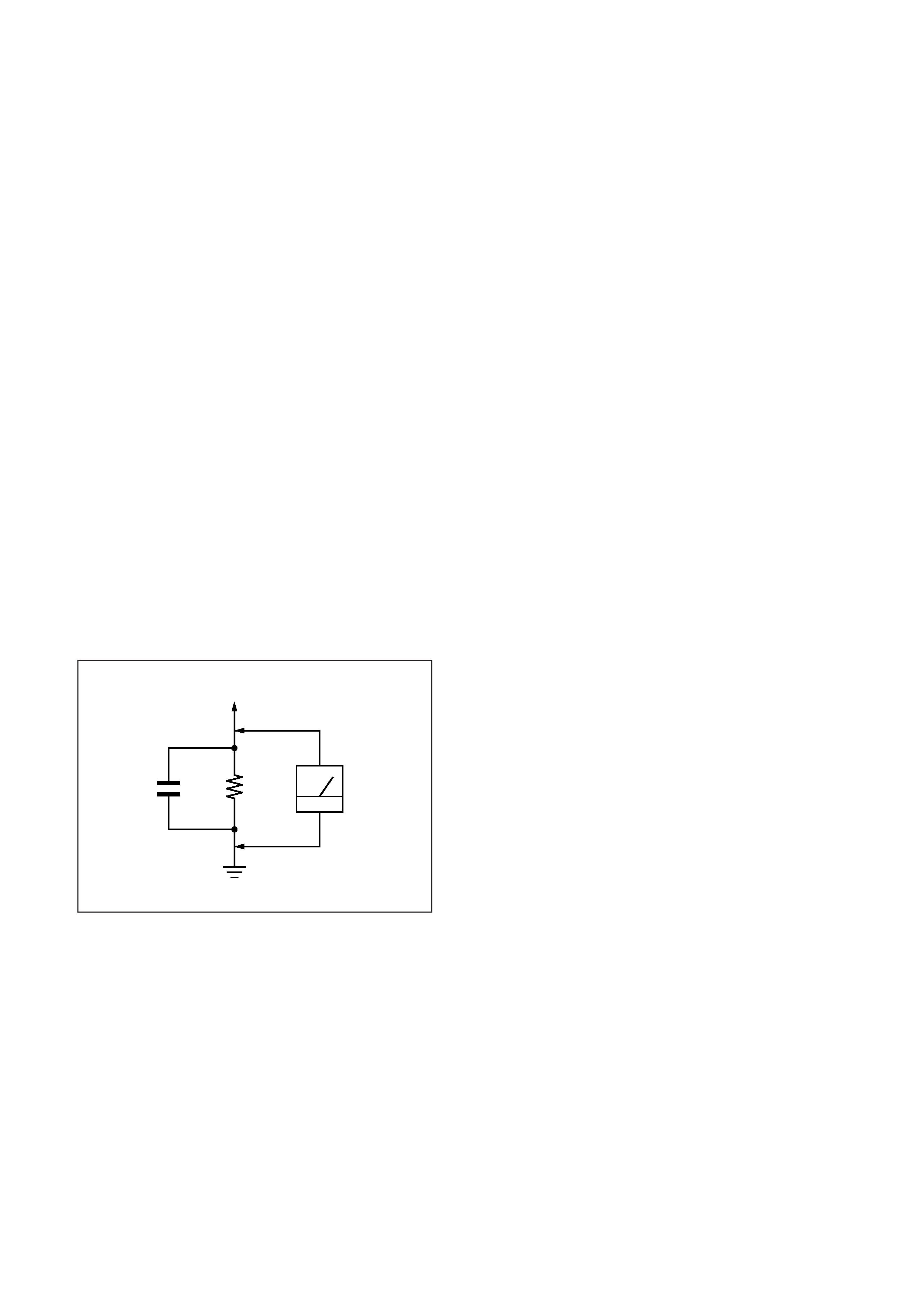
3. Measuring the voltage drop across a resistor by means of a
VOM or battery-operated AC voltmeter. The "limit" indica-
tion is 0.75 V, so analog meters must have an accurate low-
voltage scale. The Simpson 250 and Sanwa SH-63Trd are
examples of a passive VOMs that are suitable. Nearly all
battery operated digital multimeters that have a 2 V AC
range are suitable. (See Fig. A)
After correcting the original service problem, perform the fol-
lowing safety checks before releasing the set to the customer:
1. Check the area of your repair for unsoldered or poorly-sol-
dered connections. Check the entire board surface for solder
splashes and bridges.
2. Check the interboard wiring to ensure that no wires are
"pinched" or contact high-wattage resistors.
3. Check that all control knobs, shields, covers, ground straps,
and mounting hardware have been replaced. Be absolutely
certain that you have replaced all the insulators.
4. Look for unauthorized replacement parts, particularly tran-
sistors, that were installed during a previous repair. Point
them out to the customer and recommend their replacement.
5. Look for parts which, though functioning, show obvious
signs of deterioration. Point them out to the customer and
recommend their replacement.
6. Check the line cords for cracks and abrasion. Recommend
the replacement of any such line cord to the customer.
7. Check the B+ and HV to see if they are specified values.
Make sure your instruments are accurate; be suspicious of
your HV meter if sets always have low HV.
8. Check the antenna terminals, metal trim, "metallized"
knobs, screws, and all other exposed metal parts for AC
Leakage. Check leakage as described below.
Fig. A. Using an AC voltmeter to check AC leakage.
SAFETY CHECK-OUT
1.5 k
0.15
µF
AC
Voltmeter
(0.75 V)
To Exposed Metal
Parts on Set
Earth Ground
WARNING!!
NEVER TURN ON THE POWER IN A CONDITION IN
WHICH THE DEGAUSS COIL HAS BEEN REMOVED.
SAFETY-RELATED COMPONENT WARNING!!
COMPONENTS IDENTIFIED BY SHADING AND MARK
¡ ON THE SCHEMATIC DIAGRAMS, EXPLODED
VIEWS AND IN THE PARTS LIST ARE CRITICAL FOR
SAFE OPERATION. REPLACE THESE COMPONENTS
WITH SONY PARTS WHOSE PART NUMBERS AP-
PEAR AS SHOWN IN THIS MANUAL OR IN SUPPLE-
MENTS PUBLISHED BY SONY. CIRCUIT ADJUST-
MENTS THAT ARE CRITICAL FOR SAFE OPERATION
ARE IDENTIFIED IN THIS MANUAL. FOLLOW THESE
PROCEDURES WHENEVER CRITICAL COMPONENTS
ARE REPLACED OR IMPROPER OPERATION IS
SUSPECTED.
http://cxema.ru
CPD-G420
3
POWER SAVING FUNCTION
DIAGNOSIS
Failre
+B failure
Horizontal / Vertical Deflection
failure, Thermal protector
ABL protector
HV failure
Aging / Self Test
Out of scan range
Power LED
Amber
Off
(0.5 sec)
(0.5 sec)
Amber
Off
(1.5 sec)
(0.5 sec)
Amber
Off
(0.5 sec)
(1.5 sec)
Amber
Off
Amber
Off
(0.25 sec)
(0.25 sec)
(0.25 sec)
(1.25 sec)
Amber
Off
Green
Off
(0.5 sec)
(0.5 sec)
(0.5 sec)
(0.5 sec)
Green (OSD indication)
Aging Mode (Video Aging) : During Power Save, press MENU button for longer than 2 second.
Self Test (OSD Color Bar)
: During Power Save, push up Control button for longer than 2 second.
Reliability Check Mode
: During Power Save, push down Control button for longer than 2 second.
This monitor meets the power-saving guidelines set by VESA,
ENERGY STAR, and NUTEK. If no signal is input to the
monitor from your computer, the monitor will automatically
reduce power consumption as shown below.
*
Figures reflect power consumption when no USB compatible
peripherals are connected to the monitor.
** When your computer enters power saving mode, the input signal is
cut and NO SIGNAL appears on the screen before the monitor enters
active off mode. After a few seconds, the monitor enters power saving
mode.
*** "Deep sleep" is power saving mode defined by the Environmental
Protection Agency.
Power mode
Power
consumption*
! (power)
indicator
normal
operation
135 W (CPD-G520)
130 W (CPD-G420)
green
active off**
(deep sleep)***
3 W
orange
power off
Approx. 0 W
off
http://cxema.ru
CPD-G420
4
TIMING SPECIFICATION
MODE AT PRODUCTION
MODE 1
MODE 2
MODE 3
RESOLUTION
640 X 480
1280 X 1024
1600 X 1200
CLOCK
25.175 MHz
157.500 MHz
229.500 MHz
-- HORIZONTAL --
H-FREQ
31.469 kHz
91.146 kHz
106.250 kHz
usec
usec
usec
H. TOTAL
31.778
10.971
9.412
H. BLK
6.356
2.844
2.440
H. FP
0.636
0.406
0.279
H. SYNC
3.813
1.016
0.837
H. BP
1.907
1.422
1.325
H. ACTIV
25.422
8.127
6.972
-- VERTICAL --
V. FREQ (HZ)
59.940 Hz
85.024 Hz
85.000 Hz
lines
lines
lines
V. TOTAL
525
1072
1250
V. BLK
45
48
50
V. FP
10
1
1
V. SYNC
23
3
V. BP
33
44
46
V. ACTIV
480
1024
1200
-- SYNC --
INT(G)
NO
NO
NO
EXT (H/V) /POLARITY
YES N/N
YES P/P
YES P/P
EXT (CS) /POLARITY
NO
NO
NO
INT/NON INT
NON INT
NON INT
NON INT
2000.8.9 VER.

http://cxema.ru
CPD-G420
5
TABLE OF CONTENTS
Section
Title
Page
1. GENERAL ................................................................. 1-1
2. DISASSEMBLY
2-1.
Cabinet Removal ............................................... 2-1
2-2.
A1 Board (C BLOCK) Removal ....................... 2-2
2-3.
A1 Board, US Board Removal .......................... 2-2
2-4.
Bezel Assembly, H1 Board Removal ............... 2-3
2-5.
D Board Removal .............................................. 2-3
2-6.
Service Position .................................................. 2-4
2-7.
Picture Tube Removal ........................................ 2-5
2-8.
Harness Location ............................................... 2-6
3. SAFETY RELATED ADJUSTMENT ............. 3-1
4. ADJUSTMENTS ..................................................... 4-1
5. DIAGRAMS
5-1.
Block Diagrams .................................................. 5-1
5-2.
Frame Schematic Diagram ................................. 5-7
5-3.
Circuit Boards Location ..................................... 5-9
5-4.
Schematic Diagrams and Printed Wiring
Boards ................................................................. 5-9
(1)
Schematic Diagram of A1 Board ...................... 5-11
(2)
Schematic Diagram of US Board ...................... 5-15
(3)
Schematic Diagram of DA Board ..................... 5-17
(4)
Schematic Diagram of N Board ........................ 5-19
(5)
Schematic Diagrams of
D (
a, b, c) Board ........................................ 5-21
(6)
Schematic Diagram of H1 Board ....................... 5-29
(7)
Schematic Diagram of L2 Board ....................... 5-31
5-5.
Semiconductors ................................................. 5-33
6. EXPLODED VIEWS
6-1.
Chassis ............................................................... 6-1
6-2.
Picture Tube ...................................................... 6-2
6-3.
Packing Materials ............................................... 6-3
7. ELECTRICAL PARTS LIST ............................ 7-1