1
SERVICE MANUAL
SPECIFICATIONS
General
Frequency control
Crystal-controlled PLL
Operation mode
FM, duplex
Operation channel
10 channels
Supplied accessories
AC power adaptor AC-T56 (1)
Telephone line cord (1)
Rechargeable battery pack BP-T16 (1)
Directories (2 sheets)
Handset
Power source
Rechargeable battery pack BP-T16
Battery life
Standby: Approx. 14 days
Talk:
Approx. 6 hours
Dimensions
Approx. 2 3/8
× 7 3/4 × 1 7/8 inches (w/h/d), antenna
excluded (approx. 58
× 194 × 47 mm)
Antenna: Approx. 4 3/8 inches (approx. 110 mm)
Mass
Approx. 7.8 oz (approx. 220 g), battery included
Base unit
Power source
DC 9V from AC power adaptor
Battery charging time
Approx. 12 hours
Dimensions
Approx. 5 1/4
× 2 1/4 × 8 3/4 inches (w/h/d), antenna
excluded (approx. 132
× 56 × 220 mm)
Antenna: Approx. 23 5/8 inches (approx. 600 mm)
Mass
Approx. 11 oz (approx. 310 g)
Design and specifications are subject to change without notice.
SPP-151
E Model
CORDLESS TELEPHONE
Handset
Base unit
Ver 1.0 2001.04
Sony Corporation
Personal Audio Company
Shinagawa Tec Service Manual Production Group
9-873-124-11
2001D0400-1
© 2001.4

2
TABLE OF CONTENTS
1. GENERAL
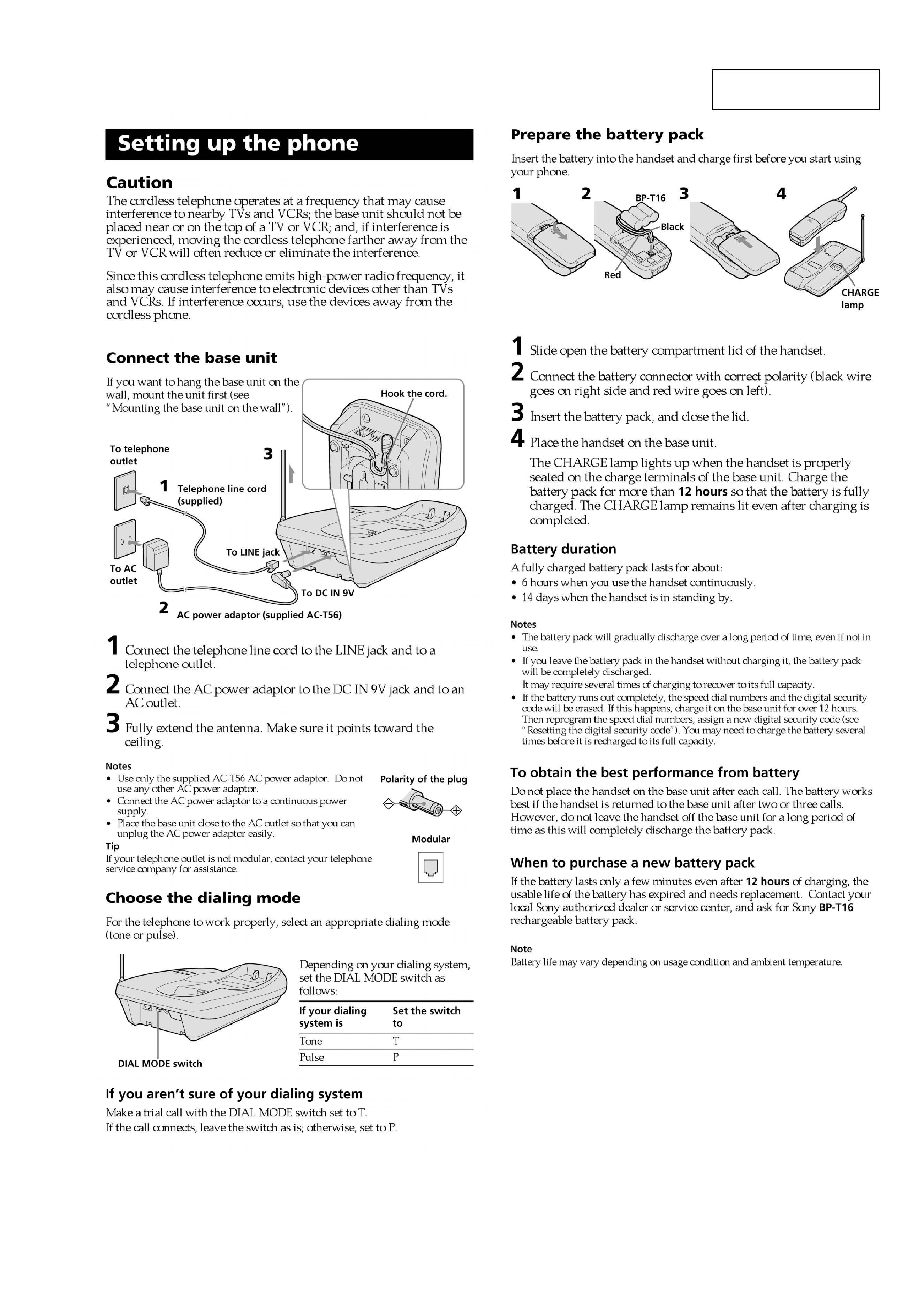
Setting up the phone ................................................................ 3
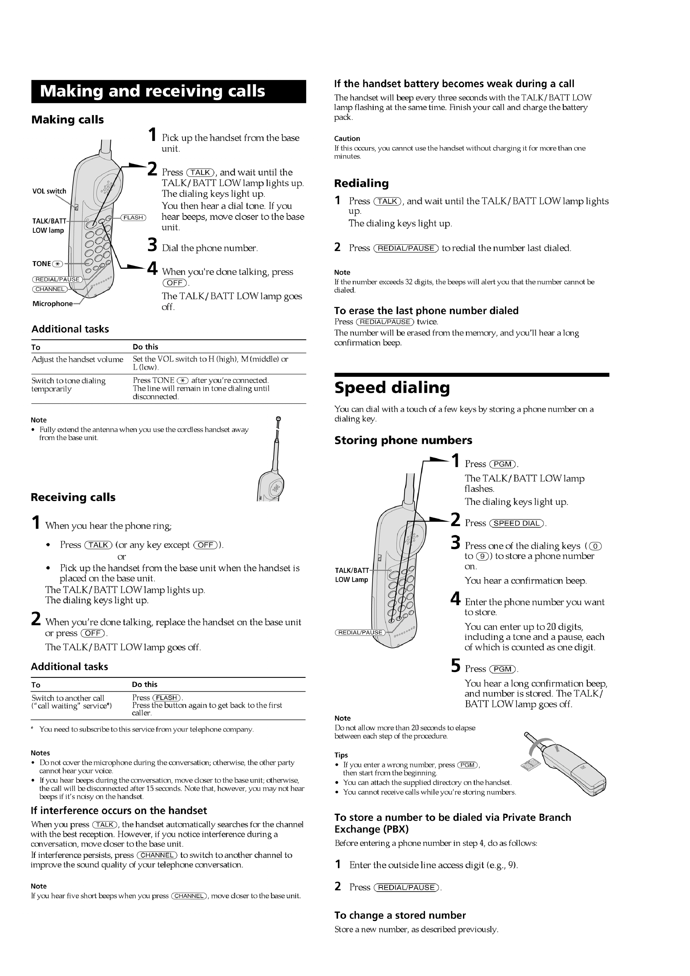
Making and receiving calls ...................................................... 4
Speed dialing ........................................................................... 4
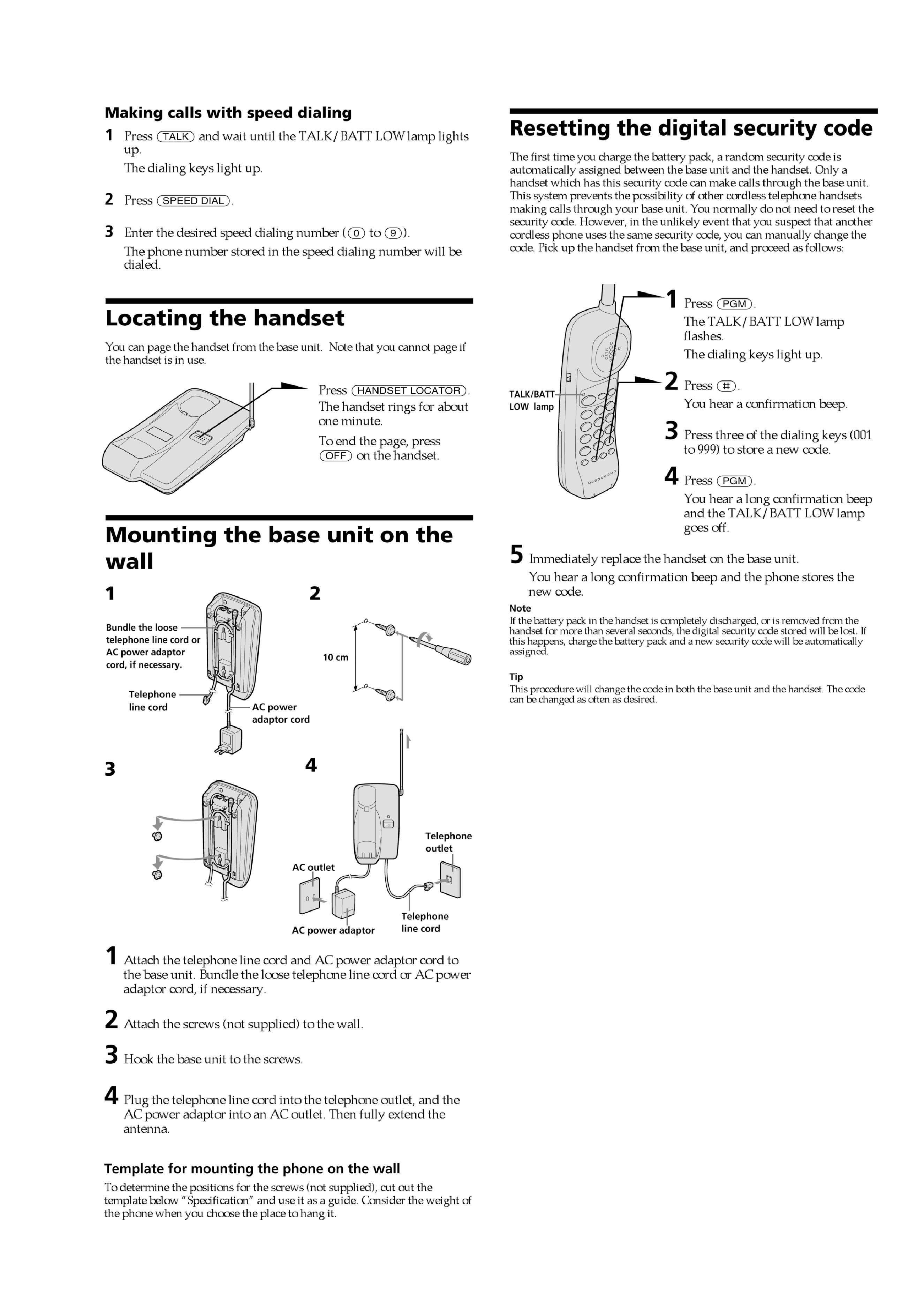
Locating the handset ................................................................ 5
Mounting the base unit on the wall ......................................... 5
Resetting the digital security code ........................................... 5
2. DISASSEMBLY
2-1. Cabinet (Lower) (Base Unit) ............................................... 6
2-2. Cabinet (Rear) (Handset) .................................................... 6
3. TEST MODE
Base Unit Section .................................................................... 7
Handset Section ....................................................................... 9
4. ELECTRICAL ADJUSTMENTS
Base Unit Section .................................................................. 12
Handset Section ..................................................................... 14
5. DIAGRAMS
5-1. IC Pin Descriptions ........................................................... 16
5-2. Block Diagram Base Unit Section ................................ 18
5-3. Block Diagram Handset Section ................................... 19
5-4. Printed Wiring Board Base Unit Section ...................... 20
5-5. Schematic Diagram Base Unit Section ......................... 21
5-6. Printed Wiring Board Handset Section ......................... 22
5-7. Schematic Diagram Handset Section ............................ 23
6. EXPLODED VIEWS
6-1. Base Unit Section .............................................................. 25
6-2. Handset Section ................................................................. 26
7. ELECTRICAL PARTS LIST ......................................... 27
Notes on Chip Component Replacement
· Never reuse a disconnected chip component.
· Notice that the minus side of a tantalum capacitor may be dam-
aged by heat.
SAFETY-RELATED COMPONENT WARNING!!
COMPONENTS IDENTIFIED BY MARK 0 OR DOTTED LINE
WITH MARK 0 ON THE SCHEMATIC DIAGRAMS AND IN
THE PARTS LIST ARE CRITICAL TO SAFE OPERATION.
REPLACE THESE COMPONENTS WITH SONY PARTS WHOSE
PART NUMBERS APPEAR AS SHOWN IN THIS MANUAL OR
IN SUPPLEMENTS PUBLISHED BY SONY.
SPP-151
3
SPP-151
SECTION 1
GENERAL
This section is extracted
from instruction manual.
4
SPP-151
5
SPP-151