Sony EMCS Co.
2005D1600-1
©2005.04
Published by DI Technical Support Section
9-876-861-11
SPK-HCA
SPK-HCA
SPORTS PACK
SPK-HCA
US Model
Canadian Model
AEP Model
Chinese Model
SERVICE MANUAL
Ver 1.1 2005. 04
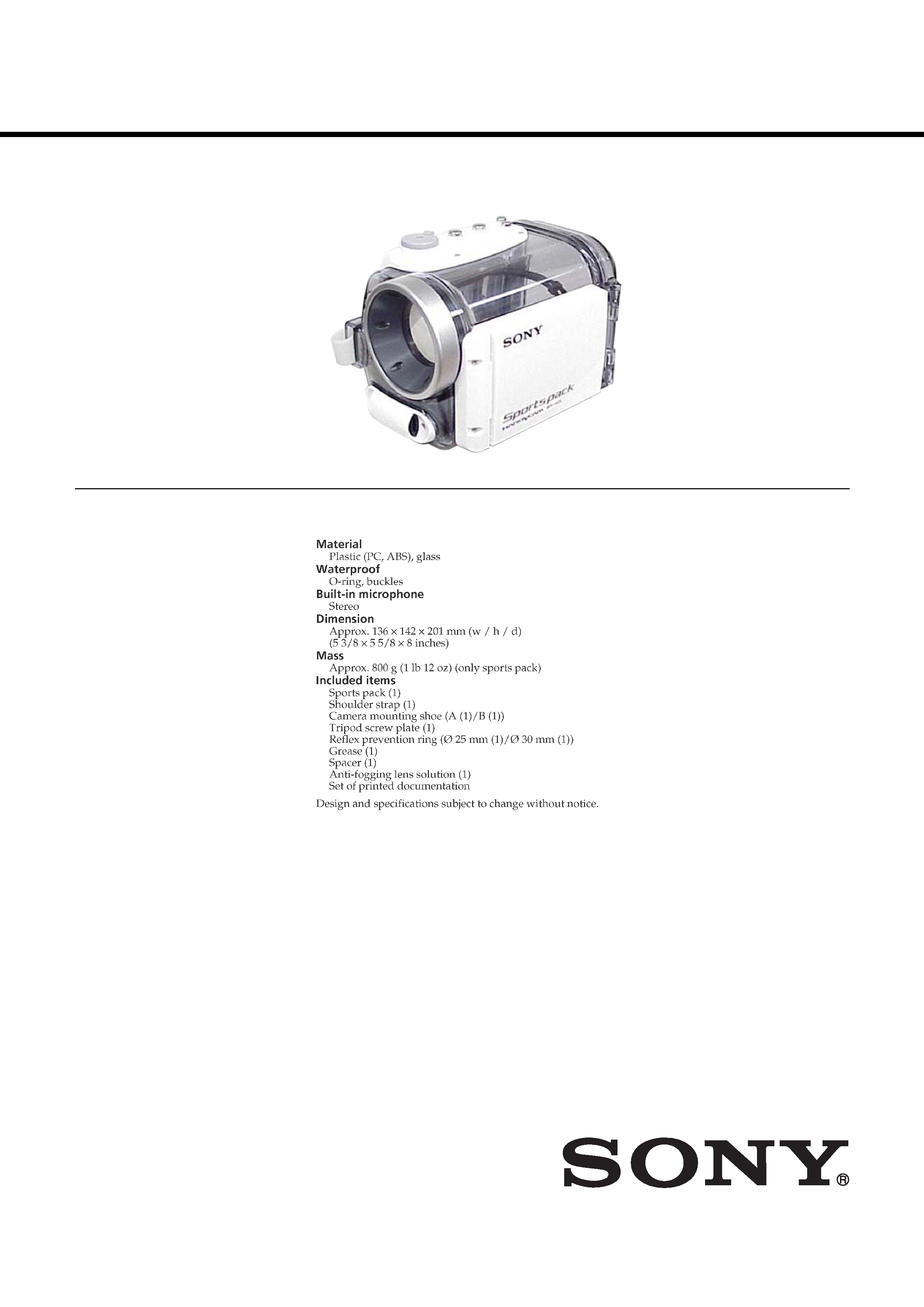
SPECIFICATIONS

-- 2 --
SPK-HCA
TABLE OF CONTENTS
SAFETY-RELATED COMPONENT WARNING!!
COMPONENTS IDENTIFIED BY MARK 0 OR DOTTED LINE WITH
MARK 0 ON THE SCHEMATIC DIAGRAMS AND IN THE PARTS
LIST ARE CRITICAL TO SAFE OPERATION. REPLACE THESE
COMPONENTS WITH SONY PARTS WHOSE PART NUMBERS
APPEAR AS SHOWN IN THIS MANUAL OR IN SUPPLEMENTS
PUBLISHED BY SONY.
ATTENTION AU COMPOSANT AYANT RAPPORT
À LA SÉCURITÉ!
LES COMPOSANTS IDENTIFÉS PAR UNE MARQUE 0 SUR LES
DIAGRAMMES SCHÉMATIQUES ET LA LISTE DES PIÈCES SONT
CRITIQUES POUR LA SÉCURITÉ DE FONCTIONNEMENT. NE
REMPLACER CES COMPOSANTS QUE PAR DES PIÈSES SONY
DONT LES NUMÉROS SONT DONNÉS DANS CE MANUEL OU
DANS LES SUPPÉMENTS PUBLIÉS PAR SONY.
1.
Check the area of your repair for unsoldered or poorly-soldered
connections. Check the entire board surface for solder splashes
and bridges.
2.
Check the interboard wiring to ensure that no wires are
"pinched" or contact high-wattage resistors.
3.
Look for unauthorized replacement parts, particularly
transistors, that were installed during a previous repair. Point
them out to the customer and recommend their replacement.
4.
Look for parts which, through functioning, show obvious signs
of deterioration. Point them out to the customer and
recommend their replacement.
5.
Check the B+ voltage to see it is at the values specified.
6.
Flexible Circuit Board Repairing
· Keep the temperature of the soldering iron around 270°C
during repairing.
· Do not touch the soldering iron on the same conductor of the
circuit board (within 3 times).
· Be careful not to apply force on the conductor when soldering
or unsoldering.
SAFETY CHECK-OUT
After correcting the original service problem, perform the following
safety checks before releasing the set to the customer.
1.
GENERAL
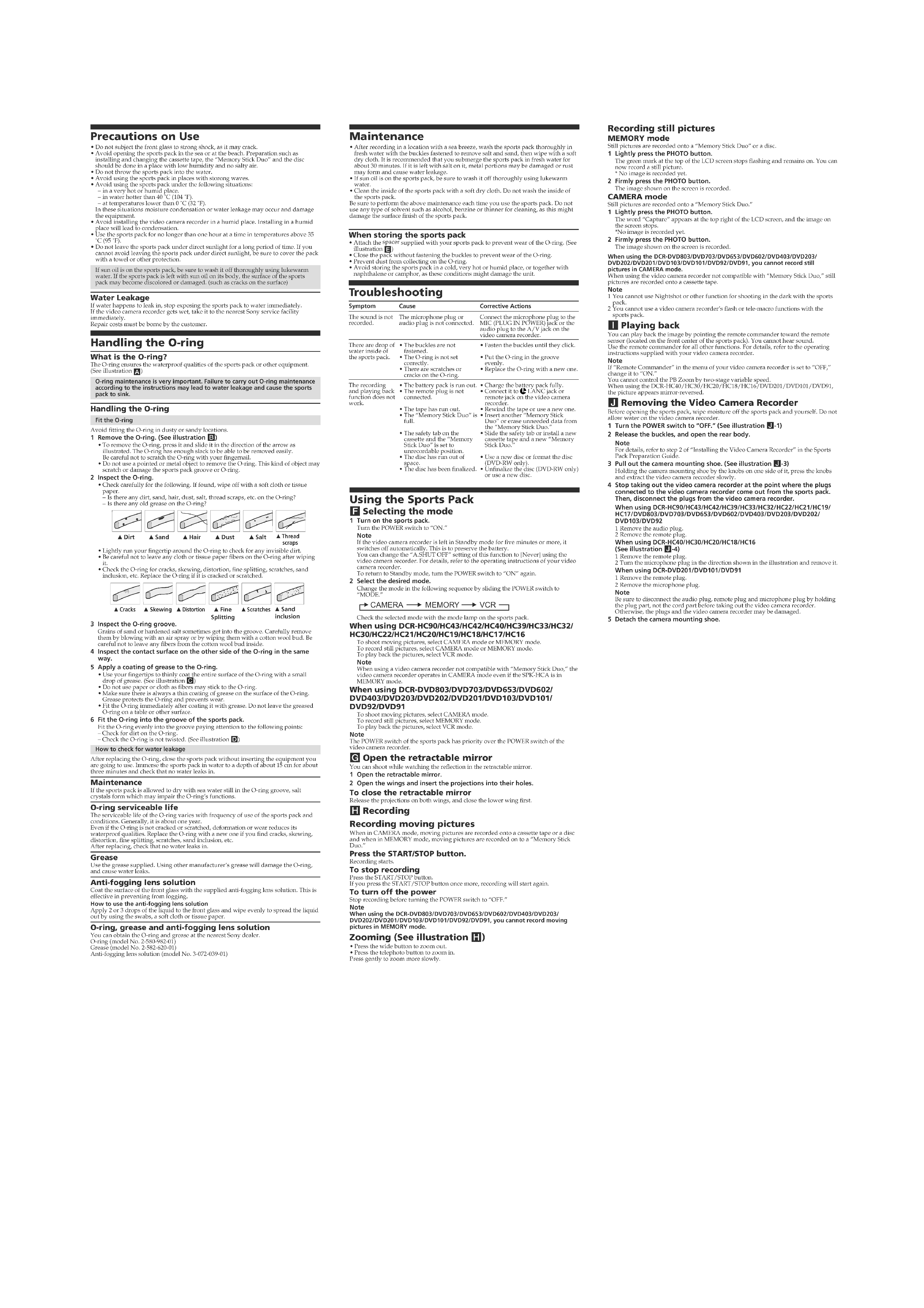
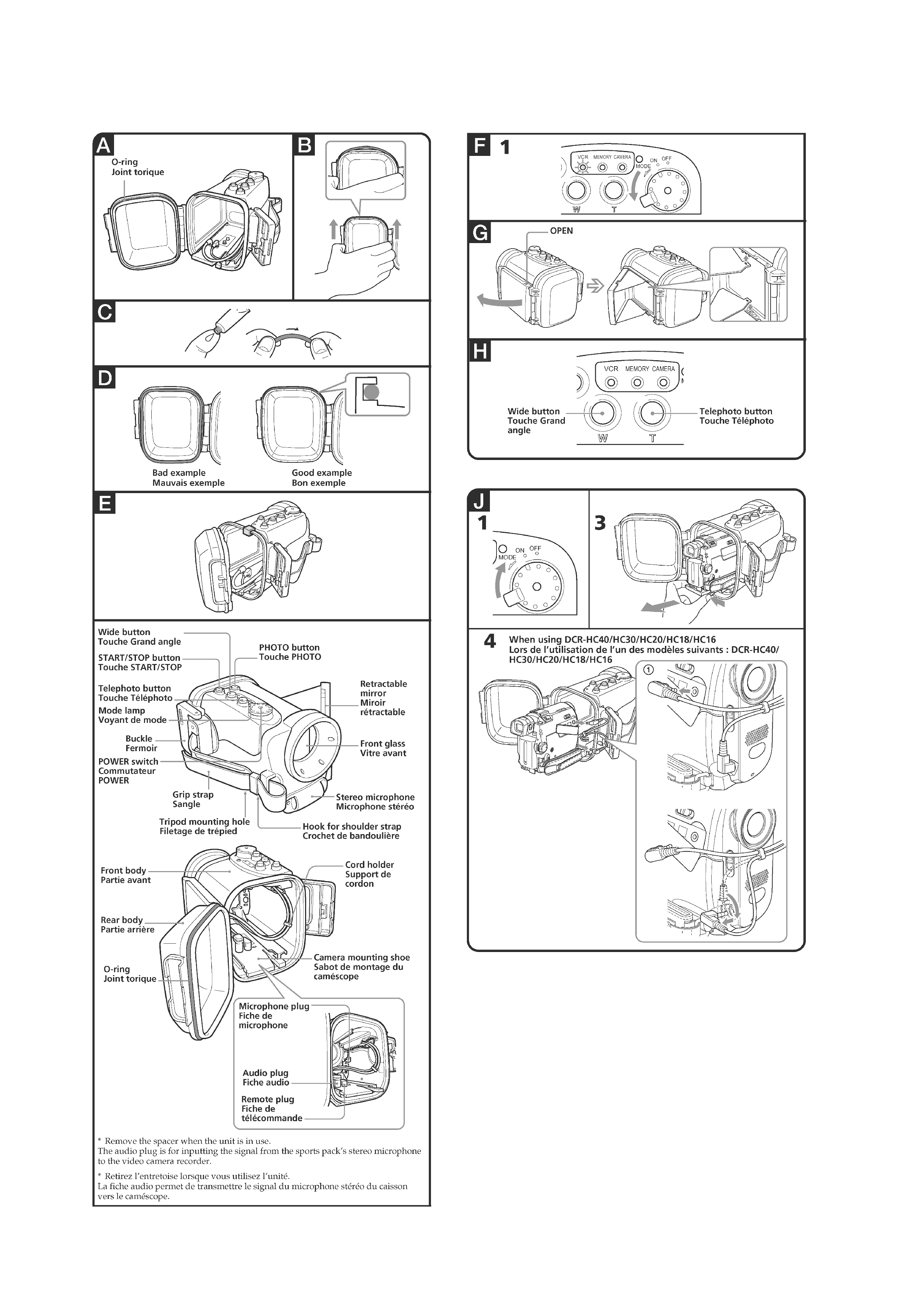
Precautions on Use ······································································· 3
Handling the O-ring ······································································ 3
Maintenance ················································································· 3
Troubleshooting ············································································ 3
Using the Sports Pack ··································································· 3
2.
REPAIR PARTS LIST
2.1
EXPLODED VIEWS ························································· 5
2-1-1. REAR CABINET SECTION ············································· 5
2-1-2. FRONT CABINET SECTION ··········································· 6
ACCESSORIES LIST ·································································· 7
-- 3 --
SPK-HCA
1. GENERAL
-- 4 --
SPK-HCA
-- 5 --
SPK-HCA
2. REPAIR PARTS LIST
2-1. EXPLODED VIEWS
NOTE:
·
-XX, -X mean standardized parts, so they may
have some differences from the original one.
·
Items marked "*" are not stocked since they
are seldom required for routine service. Some
delay should be anticipated when ordering these
items.
·
The mechanical parts with no reference number
in the exploded views are not supplied.
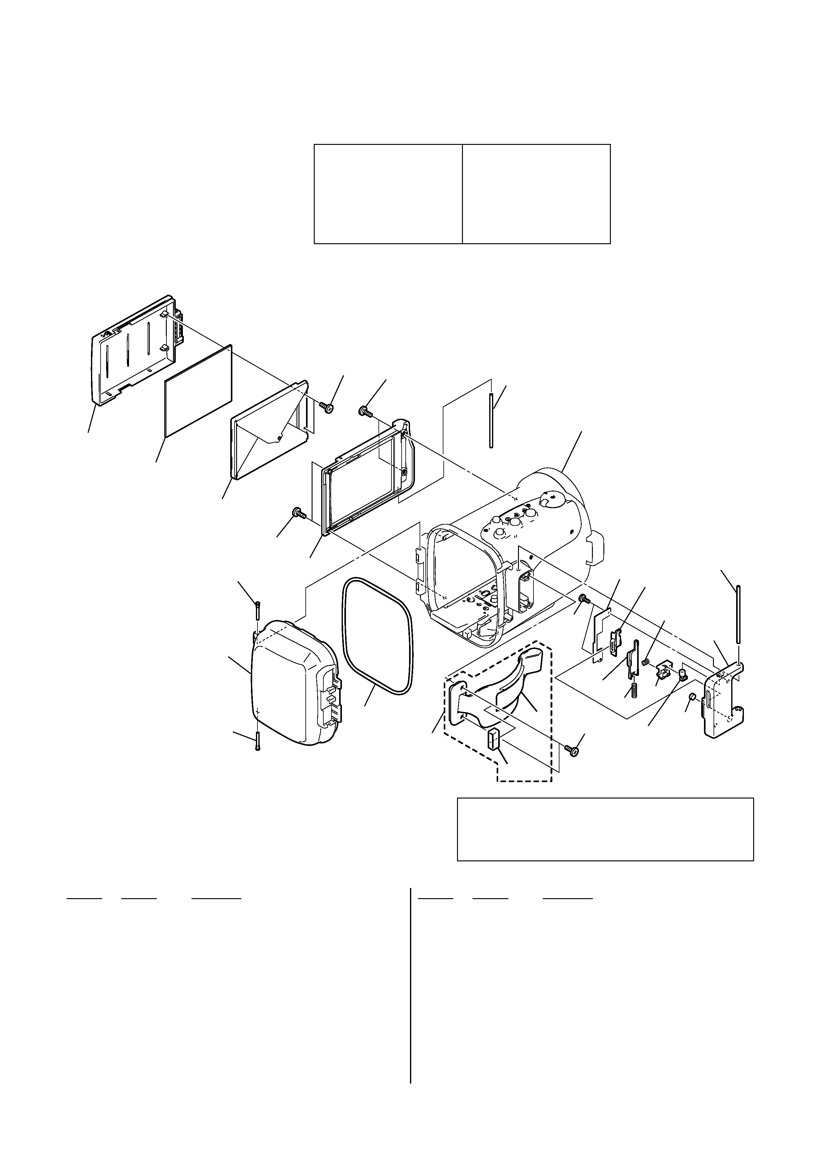
2-1-1. REAR CABINET SECTION
Ref. No.
Part No.
Description
Ref. No.
Part No.
Description
1
2-580-983-01 SHAFT, HINGE
2
2-580-981-01 CABINET R
0 3
2-580-982-01 O RING, MAIN
4
2-580-952-01 COVER, MIRROR
5
2-580-955-01 MIRROR
6
2-580-954-01 HOOD, MIRROR
7
2-580-953-01 BASE, MIRROR
8
2-580-956-01 SHAFT, MIRROR HINGE
9
3-076-866-01 BIND (2X6), TAPPING SCREW
10
A-1105-402-A GRIP BELT ASSY
11
3-960-765-01 RING, GRIP BELT
12
2-580-957-01 BUCKLE
13
3-951-813-11 SCREW (2X6) (TYPE 2), +K
0 14
3-073-881-01 CAP (RED), AIR PUNCHING
15
2-580-959-01 KNOB, BUCKLE SLIDER
16
2-589-297-01 LOCK, BUCKLE
17
3-076-875-01 SPRING, BUCKLE
18
2-593-190-01 SLIDER (LOWER), BUCKLE
19
2-589-298-01 SPRING, BUCKLE LOCK
20
2-580-958-01 SLIDER, BUCKLE
21
2-580-961-01 PLATE, BUCKLE RETAINER
1
1
2
3
4
5
6
7
8
9
9
9
13
12
14
15
16
17
18
19
20
21
ns
Front cabinet section
(See page 6)
(Note1)
9
11
10
ns
(Note1) When putting grease the main O-ring (Ref. No. 3),
always use the grease of the blue tube of the accessory.
When using the grease of the yellow tube and the grease
of the other Inc., it hurts a cabinet packing and it causes
the water leakage.
Note :
The marked "0" are parts in
relation to waterproof.
Replace these components with
Sony parts.
Be sure to check up waterproof
after repair.
Note :
La 0 marquée sont des pièces par
rapport à imperméable à l' eau.
Ne les remplacer que par une
pièce portant le numéro spécifié.
Soyez sûr de vérifier vers le haut
d' imperméable à l' eau après la
réparation.