SHR-M1
US Model
Canadian Model
AEP Model
E Model
Tourist Model
SERVICE MANUAL
PLL SYNTHESIZER
FM STEREO HEADPHONE RADIO
MICROFILM
SPECIFICATIONS
Radio segment
Frequency range:
FM 76 108 MHz (E, Tourist models)
FM 87.5 108 MHz
(US, Canadian, AEP models)
Channel Step:
0.1 MHz
Power output:
3.5 mW + 3.5 mW
Headphone segment
Headphone type:
Open-air Dynamic
Driver unit:
ø 30 mm Dome type
Input:
ø 3.5 mm stereo mini-jack
Maximum input:
100 mW
Impedance:
24
(at 1 kHz)
Frequency characteristic: 14 to 24,000 Hz
Others
Power requirements
1.5 V DC, one R03 (size AAA) battery
Mass
Approx. 99.5 g (3.5 oz) incl. a battery, not
incl. cord
Accessories supplied
Sony R03 (size AAA) battery (1)
Connecting cord (1)
Design and specifications are subject to change without notice
Ver 1.1 2000.1
-- 2 --
TABLE OF CONTENTS
1. GENERAL ·········································································· 3
2. DISASSEMBLY
2-1. Driver (030F023A)(L) ························································· 4
2-2. Jack Board ············································································· 4
2-3. Driver (030F023A)(R) ························································· 5
2-4. Main Board ··········································································· 5
2-5. Key Board ············································································· 6
2-6. Belt ························································································ 6
3. ELECTRICAL ADJUSTMENT ···································· 7
4. DIAGRAMS
4-1. Block Diagram ······································································ 9
4-2. Printed Wiring Board
Main Board ·································· 11
4-3. Schematic Diagram ·························································· 13
4-4. Printed Wiring Board
Key Board ···································· 15
4-5. Ic Pin Function Description ················································ 17
5. EXPLODED VIEWS ······················································ 18
6. ELECTRICAL PARTS LIST ······································· 19
SERVICE NOTE
In order to repair the machine while the main power is on, connecting
tool the MAIN board with the KEY board with a dedicated tool (J-
2503-012-A), is convenient.
KEY board
CN201
CN1
MAIN board
Tool (J-2503-012-A)
-- 3 --
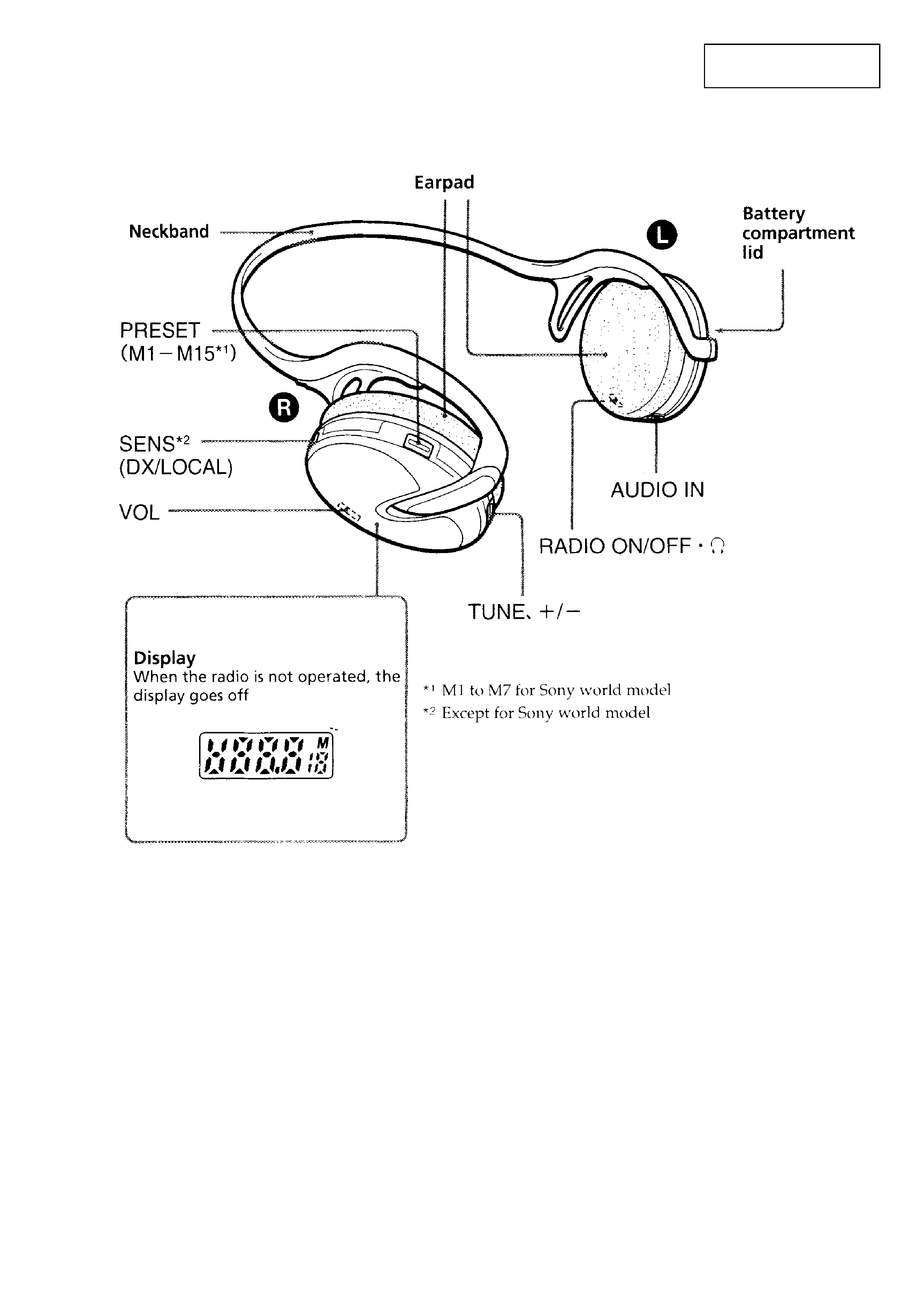
SECTION 1
GENERAL
This section is extracted
from instruction manual.
-- 4 --
SECTION 2
DISASSEMBLY
Note :
Disassemble the unit in the order as shown below.
Note :
Follow the disassembly procedure in the numerical order given.
Set
Driver (030F023A) (L)
Driver (030F023A) (R)
JACK Board
MAIN Board
KEY Board
Belt
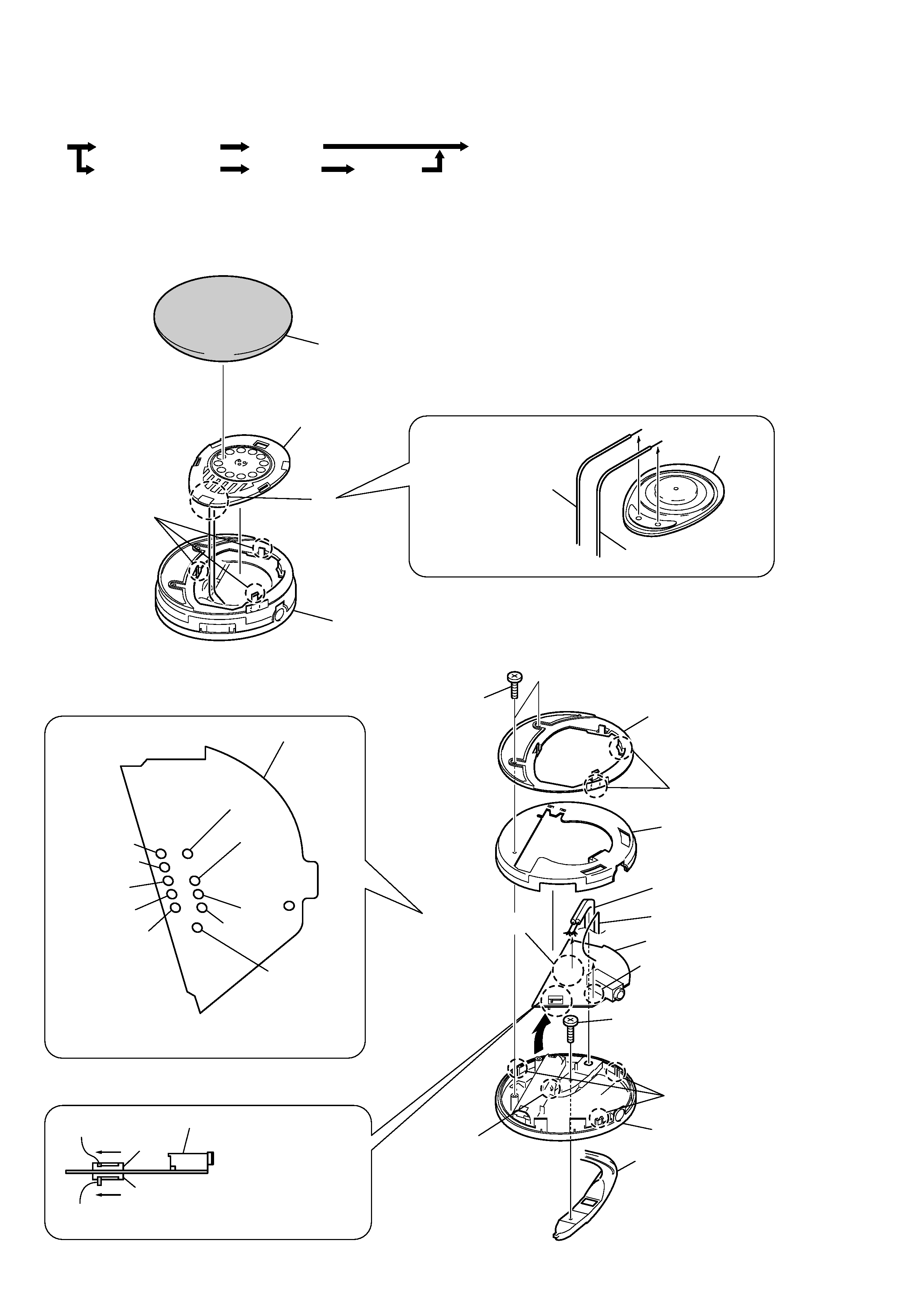
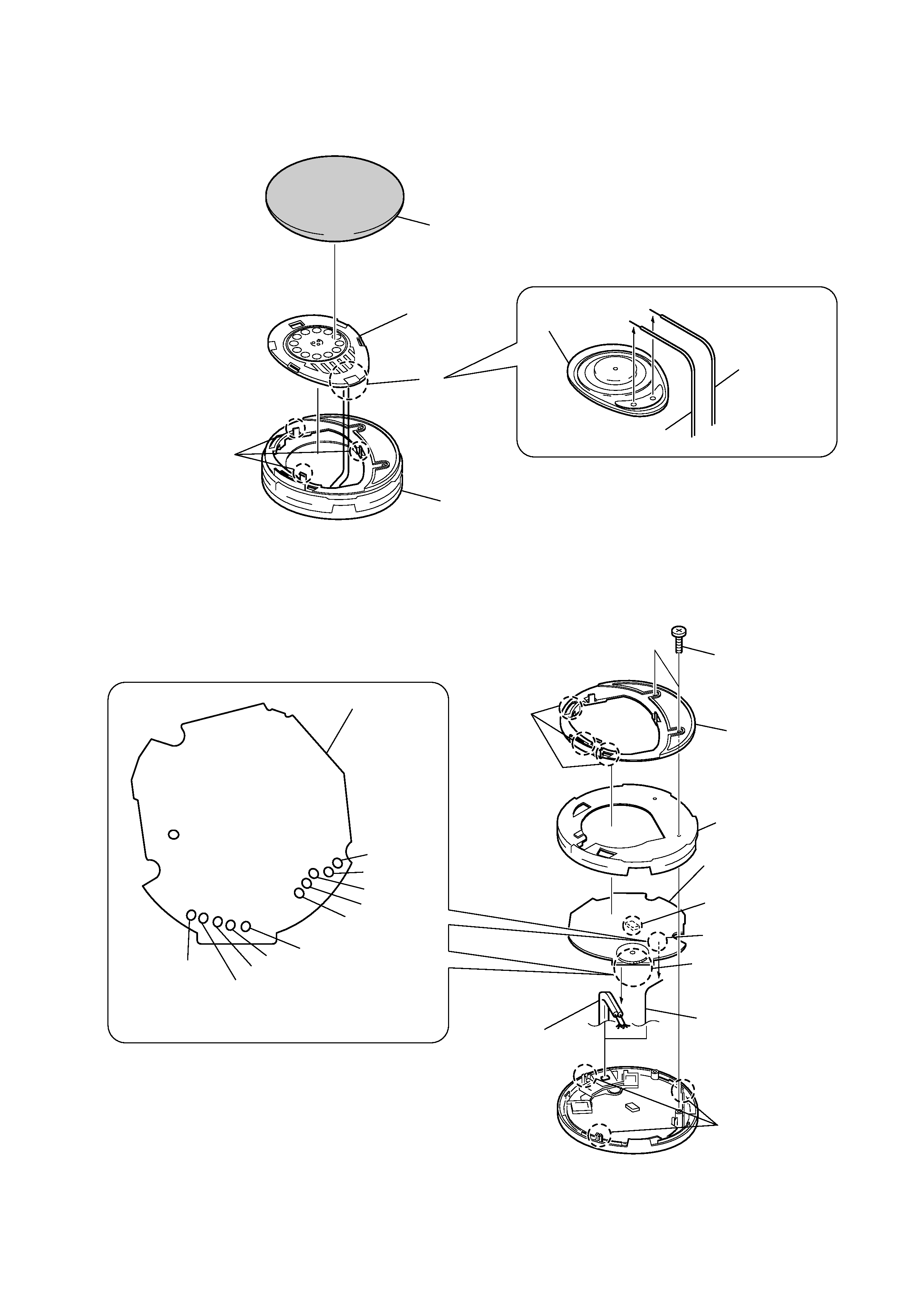
2-1. DRIVER (030F023A)(L)
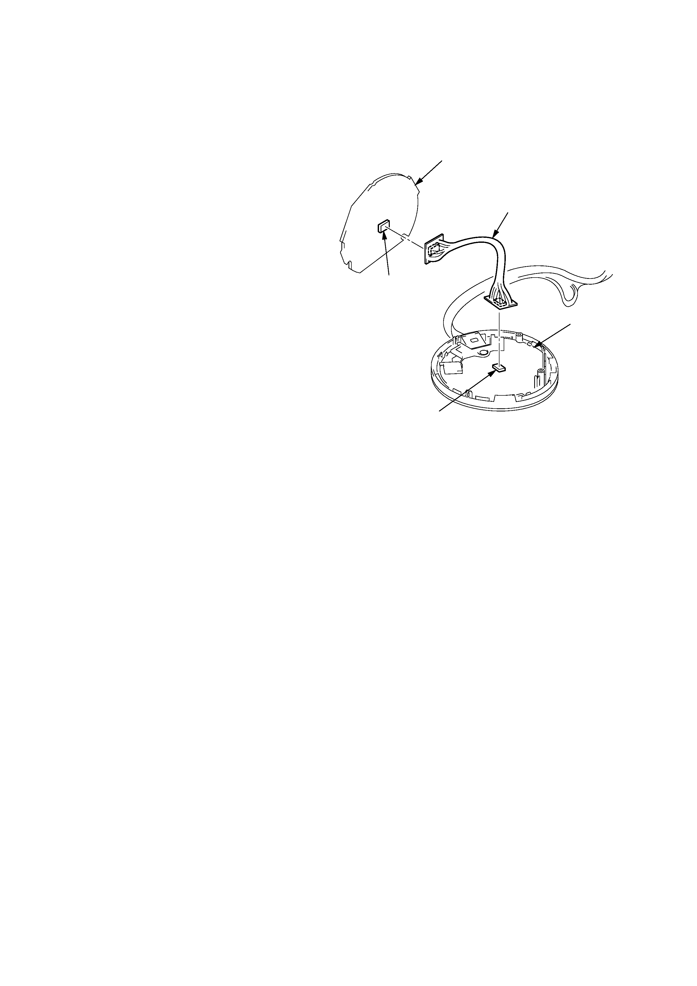
2-2. JACK BOARD
Lead wire (white)
Lead wire (red)
Rear side (Remove the two solderings.)
2
Release the
three claws.
Driver
(030F023A)
1
Pad, ear
3
4
Driver
(030F023A)
Cabinet assy
Green + Natural
Natural
Green + Natural
Green
Red
Green + Natural
Natural
4
Release the three claws.
Green + Red
Green
Red
Precaution for installation
Precaution for installation
7
Wire (10 arbor), lead
9
Lead wire (A)
qd
Cabinet (upper)(L)
Belt
0
Release the claw.
S302
J302
Knob
Slide the S301 and S302 in the direction of the arrows.
Knob
S301
qs
Screw (+P2
× 6)
qa
Remove the JACK board
in the direction of the arrow.
JACK board
5
Cabinet (main)(L)
6
Remove the ten solderings.
8
Remove the soldering.
3
Cabinet (lower)(L)
2
Release the
two claws.
1
Two screws (+P2
× 8)
Solder the lead wires (10 arbor) directly to the
position as shown while being cautious of colors.
Solder the lead wire (A) to ANT terminal directly.
ANT
-- 5 --
2-3. DRIVER (030F023A)(R)
2-4. MAIN BOARD
Lead wire (red)
Lead wire (white)
Rrear side (Remove the two solderings.)
2
Release the
three claws.
Driver (030F023A)
1
Pad, ear
3
4
Driver
(030F023A)
Cabinet assy
Green + Natural
Solder the lead wires (10 arbor) directly to the
position as shown while being cautious of colors.
Solder the lead wire (A) to ANT terminal directly.
Natural
Green + Red
Green
Red
Green + Natural
Natural
Green + Red
Green
Red
8
Wire (10 arbor), lead
6
Remove the connector.
(CN1)
q;
Lead wire (A)
qa
MAIN board
JACK board
5
Cabinet (main)(R)
7
Remove the ten solderings
from the rear side.
9
Remove the soldering
from the rear side.
3
Cabinet (lower)(R)
2
Release the
three claws.
4
Release the three claws.
1
Two screws (+P2
× 8)
Rear side
Precaution for installation
ANT