SERVICE MANUAL
Sony Corporation
Audio Group
Published by Sony Engineering Corporation
US Model
Canadian Model
AEP Model
UK Model
E Model
ACTIVE SUBWOOFER
9-879-144-01
2004H1678-1
© 2004.08
Ver 1.0 2004.08
SPECIFICATIONS
SA-WSLF1
· SA-WSLF1 is amplifier/subwoofer and tuner
system in DAV-LF1.
AUDIO POWER SPECIFICATIONS
POWER OUTPUT AND
TOTAL HARMONIC
DISTORTION:
With 4 ohm loads, both
channels driven, from
200 20,000 Hz; rated
65 watts per channel
minimum RMS power,
with no more than 0.7 %
total harmonic distortion
from 250 milli watts to
rated output.
Amplifier section
Stereo mode (rated)
86 W + 86 W (4 ohms at
1 kHz, THD 10 %)
Surround mode
Front:
86 W (each)
(reference)
(with SS-TSLF1)
music power output
Center*:
86 W
(with SS-CTLF1)
Surround (R)*:
86 W
(with SS-TSLF1W)
Surround (L):
86 W
(with SA-TSLF1)
Subwoofer*:
85 W
× 2
(with SA-WSLF1)
*Depending on the sound field settings and the source,
there may be no sound output.
Inputs
VIDEO/TV/SAT:
Sensitivity: 300 mV
Impedance: 50 kilohms
Phones
Accepts low-and high-
impedance headphones.
Tuner section
System
PLL quartz-locked digital
synthesizer system
FM tuner section
Tuning range
87.5 108.0 MHz (50 kHz
step)
Antenna (aerial)
FM wire antenna (aerial)
Antenna (aerial) terminals
75 ohms, unbalanced
Intermediate frequency
10.7 MHz
AM tuner section
Tuning range
Middle Easten models:
531 1,602 kHz (with the
interval set at 9 kHz)
Other models:
531 1,602 kHz (with the
interval set at 9 kHz)
530 1,710 kHz (with the
interval set at 10 kHz)
Antenna (aerial)
AM loop antenna (aerial)
Intermediate frequency
450 kHz
Video section
Outputs
Video: Vp-p 75 ohms
S video:
Y: 1 Vp-p 75 ohms
C: 0.286 Vp-p 75 ohms
COMPONENT:
Y: 1 Vp-p 75 ohms
PB/CB, PR/CR: 0.7 Vp-p
75 ohms
Inputs
Video: 1 Vp-p 75 ohms
Subwoofer
Speaker system
Bass reflex
Speaker unit
180 mm (7 1/8 inches)
dia. cone type
Rated impedance
4 ohms
× 2
Dimensions (approx.)
241
× 606 × 241 mm
(9 1/2 × 23
7/
8 9 ×
1/
2
inches) (w/h/d)
Mass (approx.)
14 kg (30 lb 14 oz)
Power requirements
North American and
Mexican models:
120 V AC, 60 Hz
Taiwan model:
120 V AC, 50/60 Hz
Other models:
220-240 V AC, 50/60 Hz
Power consumption
120 W
0.3 W (at the Power
Saving mode)
Design and specifications are subject to change
without notice.
2
SA-WSLF1
SAFETY CHECK-OUT
After correcting the original service problem, perform the following
safety check before releasing the set to the customer:
Check the antenna terminals, metal trim, "metallized" knobs, screws,
and all other exposed metal parts for AC leakage.
Check leakage as described below.
LEAKAGE TEST
The AC leakage from any exposed metal part to earth ground and
from all exposed metal parts to any exposed metal part having a
return to chassis, must not exceed 0.5 mA (500 microamperes.).
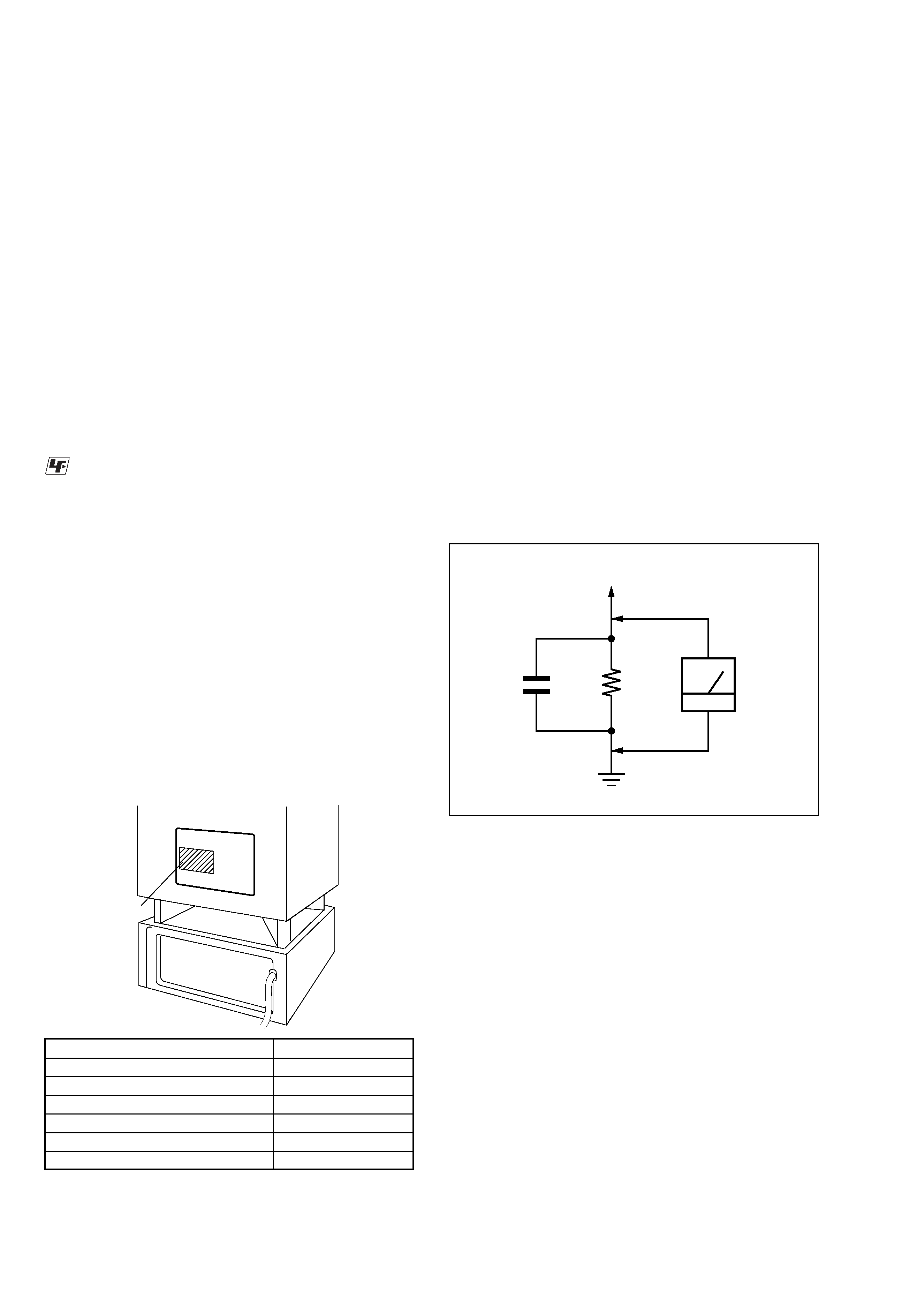
Leakage current can be measured by any one of three methods.
1. A commercial leakage tester, such as the Simpson 229 or RCA
WT-540A. Follow the manufacturers' instructions to use these
instruments.
2. A battery-operated AC milliammeter. The Data Precision 245
digital multimeter is suitable for this job.
3. Measuring the voltage drop across a resistor by means of a
VOM or battery-operated AC voltmeter. The "limit" indication
is 0.75 V, so analog meters must have an accurate low-voltage
scale. The Simpson 250 and Sanwa SH-63Trd are examples
of a passive VOM that is suitable. Nearly all battery operated
digital multimeters that have a 2 V AC range are suitable. (See
Fig. A)
1.5 k
0.15
µF
AC
voltmeter
(0.75 V)
To Exposed Metal
Parts on Set
Earth Ground
Fig. A.
Using an AC voltmeter to check AC leakage.
Notes on chip component replacement
· Never reuse a disconnected chip component.
· Notice that the minus side of a tantalum capacitor may be
damaged by heat.
Flexible Circuit Board Repairing
· Keep the temperature of the soldering iron around 270 °C
during repairing.
· Do not touch the soldering iron on the same conductor of the
circuit board (within 3 times).
· Be careful not to apply force on the conductor when soldering
or unsoldering.
UNLEADED SOLDER
Boards requiring use of unleaded solder are printed with the lead-
free mark (LF) indicating the solder contains no lead.
(Caution: Some printed circuit boards may not come printed with
the lead free mark due to their particular size)
: LEAD FREE MARK
Unleaded solder has the following characteristics.
· Unleaded solder melts at a temperature about 40 °C higher
than ordinary solder.
Ordinary soldering irons can be used but the iron tip has to be
applied to the solder joint for a slightly longer time.
Soldering irons using a temperature regulator should be set to
about 350
°C.
Caution: The printed pattern (copper foil) may peel away if
the heated tip is applied for too long, so be careful!
· Strong viscosity
Unleaded solder is more viscou-s (sticky, less prone to flow)
than ordinary solder so use caution not to let solder bridges
occur such as on IC pins, etc.
· Usable with ordinary solder
It is best to use only unleaded solder but unleaded solder may
also be added to ordinary solder.
SAFETY-RELATED COMPONENT WARNING!!
COMPONENTS IDENTIFIED BY MARK 0 OR DOTTED LINE
WITH MARK 0 ON THE SCHEMATIC DIAGRAMS AND IN
THE PARTS LIST ARE CRITICAL TO SAFE OPERATION.
REPLACE THESE COMPONENTS WITH SONY PARTS WHOSE
PART NUMBERS APPEAR AS SHOWN IN THIS MANUAL OR
IN SUPPLEMENTS PUBLISHED BY SONY.
ATTENTION AU COMPOSANT AYANT RAPPORT
À LA SÉCURITÉ!
LES COMPOSANTS IDENTIFIÉS PAR UNE MARQUE 0 SUR
LES DIAGRAMMES SCHÉMATIQUES ET LA LISTE DES
PIÈCES
SONT
CRITIQUES
POUR
LA
SÉCURITÉ
DE
FONCTIONNEMENT. NE REMPLACER CES COM- POSANTS
QUE PAR DES PIÈCES SONY DONT LES NUMÉROS SONT
DONNÉS DANS CE MANUEL OU DANS LES SUPPLÉMENTS
PUBLIÉS PAR SONY.
MODEL IDENTIFICATION
Rear Side
Model Name
Part No.
AEP, UK, Russian models
2-318-584-0[]
US, CND models
2-320-434-0[]
EA, E41 models
2-320-799-0[]
MX model
2-320-800-0[]
KR model
2-320-801-0[]
SP, HK models
Part No.
·Abbreviation
CND
: Canadian model.
E41
: Chilean and peruvian models.
EA
: Saudi Arabia model.
HK
: Hong Kong model.
KR
: Korea model.
MX
: Mexican model.
RU
: Russian model.
SP
: Singapore model.

3
SA-WSLF1
TABLE OF CONTENTS
1.
SERVICING NOTES ................................................ 4
2.
GENERAL ................................................................... 6
3.
ELECTRICAL ADJUSTMENTS .......................... 7
4.
DIAGRAMS
4-1.
Block Diagram
-- AMP (DSP) Section -- ..................
9
-- AUDIO (OUT) Section -- .......................................... 10
-- VIDEO Section -- ...................................................... 11
-- DIAT TRANSMITTER Section -- ............................ 12
4-2.
Printed Wiring Board
-- JACK COMB Section (Side A) -- ............................. 13
4-3.
Printed Wiring Board
-- JACK COMB Section (Side B) -- ............................. 14
4-4.
Schematic Diagram -- JACK COMB Section -- .......... 15
4-5.
Printed Wiring Board
-- SW-MAIN Section (Side A) -- .................................. 16
4-6.
Printed Wiring Board
-- SW-MAIN Section (Side B) -- .................................. 17
4-8.
Schematic Diagram -- SW-MAIN Section (1/4) -- ...... 18
4-9.
Schematic Diagram -- SW-MAIN Section (2/4) -- ...... 19
4-10. Schematic Diagram -- SW-MAIN Section (3/4) -- ...... 20
4-11. Schematic Diagram -- SW-MAIN Section (4/4) -- ...... 21
4-12. Printed Wiring Board -- AMP Section (Side A) -- ....... 22
4-13. Printed Wiring Board -- AMP Section (Side B) -- ....... 23
4-14. Schematic Diagram -- AMP Section (1/4) -- ............... 24
4-15. Schematic Diagram -- AMP Section (2/4) -- ............... 25
4-16. Schematic Diagram -- AMP Section (3/4) -- ............... 26
4-17. Schematic Diagram -- AMP Section (4/4) -- ............... 27
4-18. Printed Wiring Board
-- DIAT TRANSMITTER Section -- ............................ 28
4-19. Schematic Diagram
-- DIAT TRANSMITTER Section -- ............................ 29
4-20. Printed Wiring Board -- POWER Section -- ................ 30
4-21. Schematic Diagram -- POWER Section -- .................. 31
5.
EXPLODED VIEWS
5-1.
AMP Section-1 ................................................................ 42
5-2.
AMP Section-2 ................................................................ 43
5-3.
Overall Section ................................................................ 44
6.
ELECTRICAL PARTS LIST .................................. 45
4
SA-WSLF1
SECTION 1
SERVICING NOTES
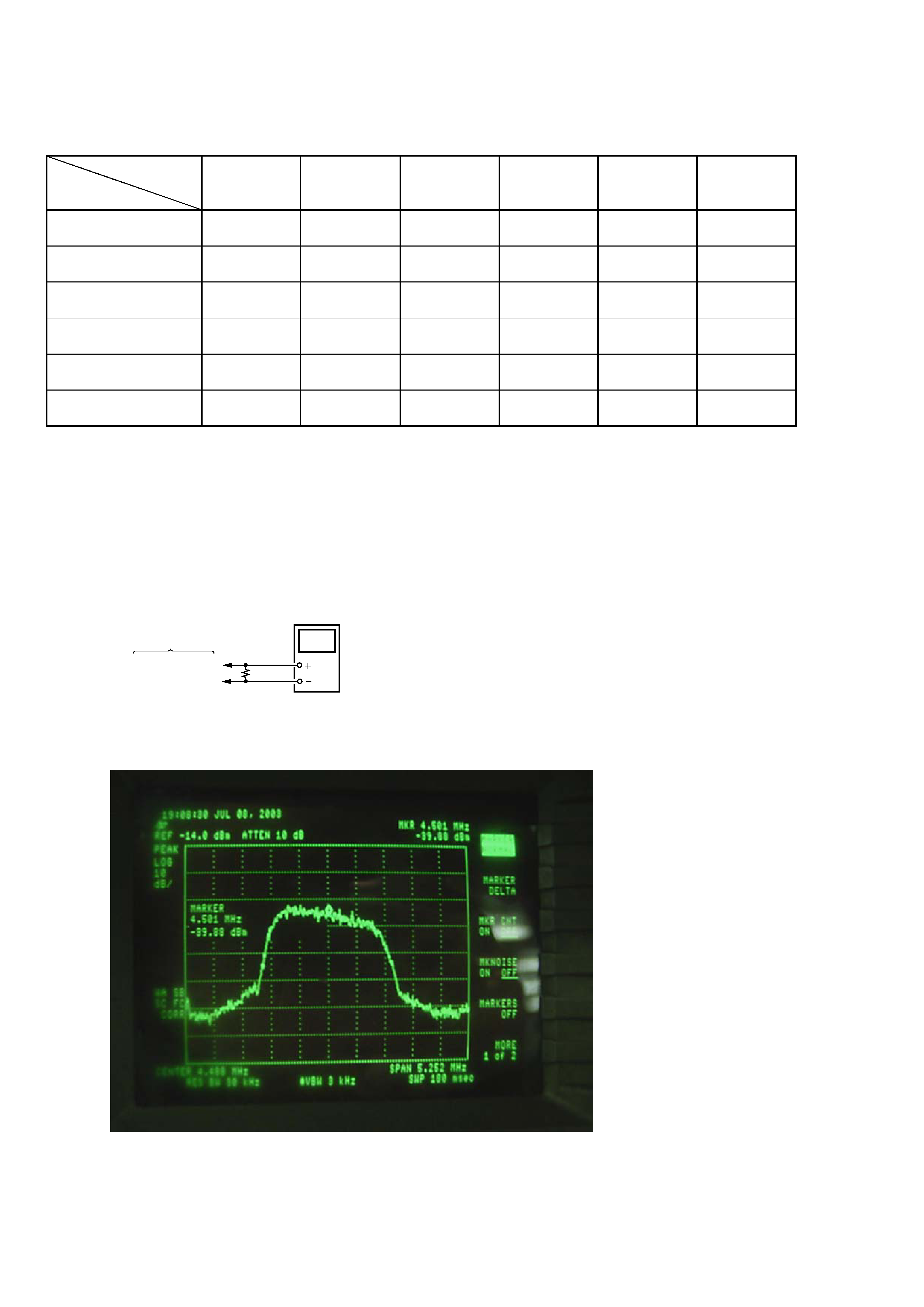
[The check method of the output signal from DIAT TRANSMITTER board]
Procedure:
1. A spectrum analyzer is connected to pin 2 and pin 1 of the output connector CN803 of DIAT TRANSMITTER board.
2. Confirm that it is spectrum as shown in a figure with the spectrum analyzer. It is normal if the signal of a 3MHz to 6MHz zone (a center
is 4.5MHz) can be checked.
digital
voltmeter
10
(0.5%)
DIAT TRANSMITTER
board
CN803 Pin 1
Pin 2
3. When the output signal from DIAT TRANSMITTER board is normal, pin 8 (SDATA), pin 4 (LRCKO) and pin 5 (BCKO) of the input
signal connector CN801 are investigated.
DVD player :
HCD-LF1
DVD player : HCD-LF1
Sub woofer :
SA-WSLF1
Sub woofer : SA-WSLF1
Front speaker :
SS-TSLF1(R)
SS-TSLF1L(L)
Front speaker : SS-TSLF1(R)
SS-TSLF1L(L)
Center speaker :
SS-CTLF1
Center speaker :
SS-CTLF1
Surround speaker :
SS-TSLF1W(R)
SA-TSLF1(L)
Surround speaker : SS-TSLF1W(R)
SA-TSLF1(L)
Remote
commander :
RM-SP320
Remote commander :
RM-SP320
Units required for
operation
check
Unit.
need to
checking
aa
a
aa
a
aa
a
a
a
a
aa
a
a
a
*1
*1
*2
*1 Only the defective unit. *2 Either one of them.
Units with a mark: The units that are required for the system operation check during repair service
However, there can be a case that some units of the system need to not be brought into repair shop depending on the unit. that became defective.
· The units that are required for the system operation check during repair service
5
SA-WSLF1
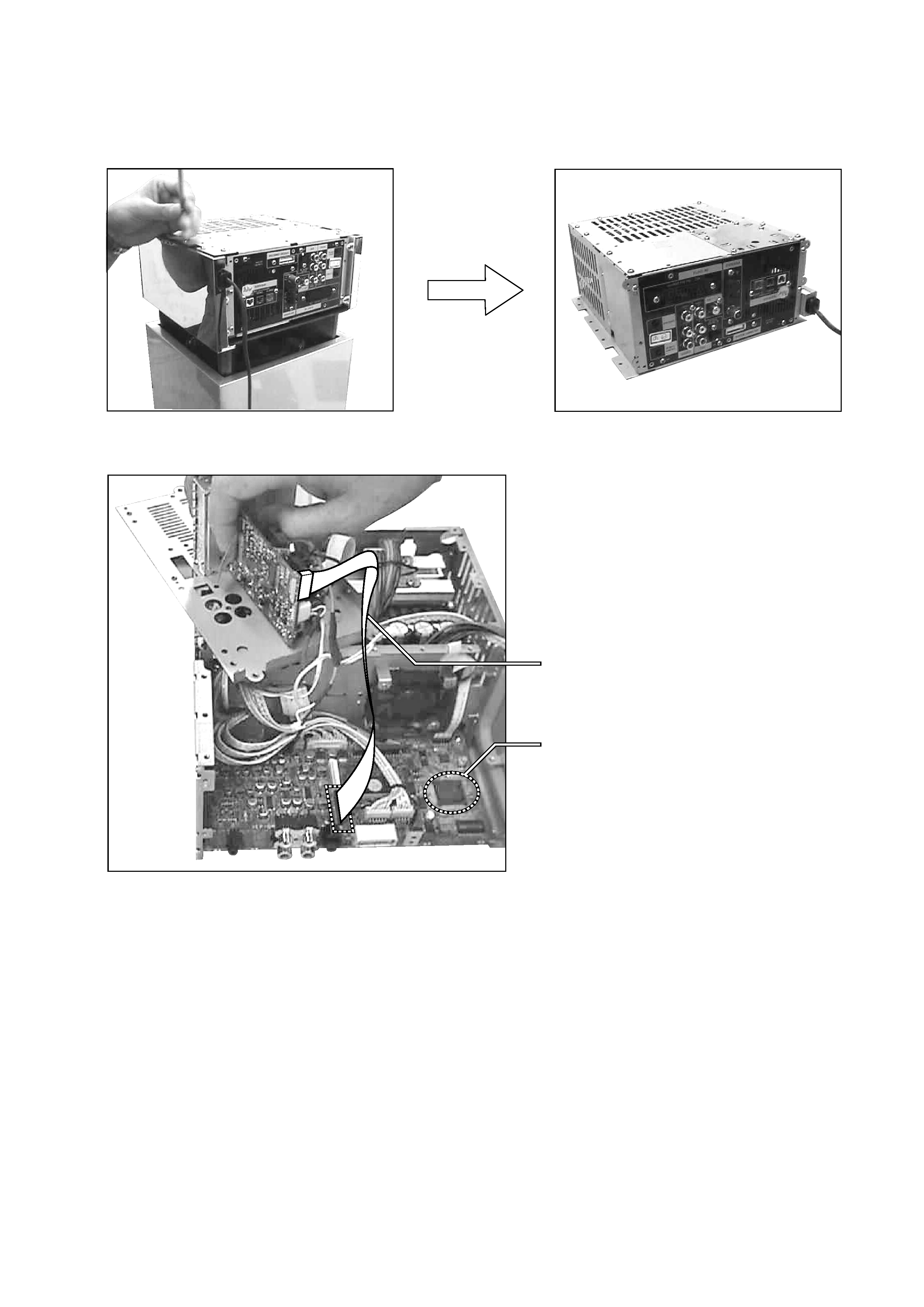
·NOTE:
Turn the woofer upside down and remove the AMP block.
Connect the SW-MAIN board and the VIDEO-I/O board
using the extension cable and check the SW-MAIN board.
J-2501-245-A
(1mm/23P/L300)
IC525 on the SW-MAIN board
· SERVICING POSITION (SW-MAIN Board)
·CAUTION:
Keep your eyes 10 cm or more away from the infrared laser unit (DIR-T1).
Do not view directly the laser beam.