1
SERVICE MANUAL
US Model
Canadian Model
AEP Model
UK Model
E Model
SA-WM250
ACTIVE SUBWOOFER
Ver 1.0 2004.03
Sony Corporation
Home Audio Company
Published by Sony Engineering Corporation
9-877-696-01
2004C04-1
© 2004.03
AUDIO POWER SPECIFICATIONS
POWER OUTPUT AND TOTAL HARMONIC
DISTORTION:
With 6 ohm loads, from 28 200 Hz; rated 100 watts,
minimum RMS power, with no more than 0.8 % total
harmonic distortion from 250 milliwatts to rated
output.
System
Type
Active Subwoofer (magnetically shielded design)
Speaker unit
Woofer: 20 cm dia. (8 in.), cone type
RMS output
100 W (6 Ohms, 40 Hz, 10% THD)
Frequency range
28 Hz 200 Hz
High frequency cut-off frequency
50 Hz 200 Hz
Phase selector
NORMAL, REVERSE
SPECIFICATIONS
Inputs
Input jacks
INPUT: input pin jack
SPEAKER IN: input terminals
Output jacks
SPEAKER OUT: output terminals
General
Power requirements
Taiwan models: 110 V AC, 50 Hz
USA and Canada models: 120 V AC, 60 Hz
Other models: 230 V AC, 50/60 Hz
Power consumption
100 W
Dimensions
Approx. 290
× 355 × 387 mm
(11 3/8
× 14 × 15 1/4 in.) (w/h/d)
Mass
11.5 kg (25 lb 6 oz)
Supplied accessories
Foot pads (4)
Audio connecting cord (1 phono 1 phono),
2 m (6 ft 6 1/2 in.) (1)
Speaker cords, 2.5 m (8 ft 2 1/2 in.) (2)
Design and specifications are subject to change without notice.
2
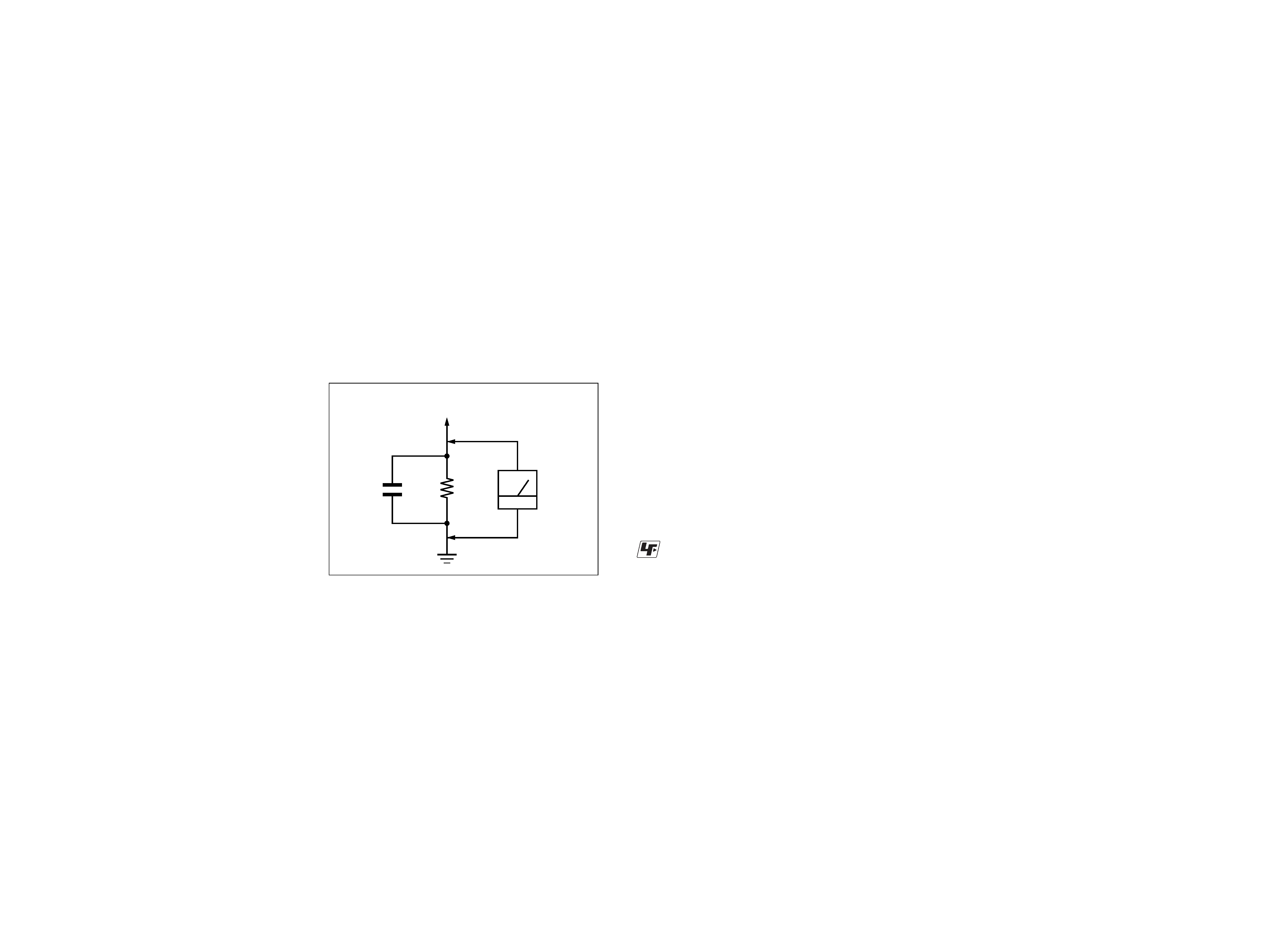
1.5 k
0.15 µF
AC
voltmeter
(0.75 V)
To Exposed Metal
Parts on Set
Earth Ground
SAFETY CHECK-OUT
After correcting the original service problem, perform the follow-
ing safety check before releasing the set to the customer:
Check the antenna terminals, metal trim, "metallized" knobs, screws,
and all other exposed metal parts for AC leakage.
Check leakage as described below.
LEAKAGE TEST
The AC leakage from any exposed metal part to earth ground and
from all exposed metal parts to any exposed metal part having a
return to chassis, must not exceed 0.5 mA (500 microampers.).
Leakage current can be measured by any one of three methods.
1. A commercial leakage tester, such as the Simpson 229 or RCA
WT-540A. Follow the manufacturers' instructions to use these
instruments.
2. A battery-operated AC milliammeter. The Data Precision 245
digital multimeter is suitable for this job.
3. Measuring the voltage drop across a resistor by means of a
VOM or battery-operated AC voltmeter. The "limit" indica-
tion is 0.75 V, so analog meters must have an accurate low-
voltage scale. The Simpson 250 and Sanwa SH-63Trd are ex-
amples of a passive VOM that is suitable. Nearly all battery
operated digital multimeters that have a 2 V AC range are suit-
able. (See Fig. A)
SAFETY-RELATED COMPONENT WARNING!!
COMPONENTS IDENTIFIED BY MARK 0 OR DOTTED LINE
WITH MARK 0 ON THE SCHEMATIC DIAGRAMS AND IN
THE PARTS LIST ARE CRITICAL TO SAFE OPERATION.
REPLACE THESE COMPONENTS WITH SONY PARTS WHOSE
PART NUMBERS APPEAR AS SHOWN IN THIS MANUAL OR
IN SUPPLEMENTS PUBLISHED BY SONY.
ATTENTION AU COMPOSANT AYANT RAPPORT
À LA SÉCURITÉ!!
LES COMPOSANTS IDENTIFIÉS PAR UNE MARQUE 0 SUR LES
DIAGRAMMES SCHÉMATIQUES ET LA LISTE DES PIÈCES SONT
CRITIQUES POUR LA SÉCURITÉ DE FONCTIONNEMENT. NE
REMPLACER CES COMPOSANTS QUE PAR DES PIÈCES SONY
DONT LES NUMÉROS SONT DONNÉS DANS CE MANUEL OU
DANS LES SUPPLÉMENTS PUBLIÉS PAR SONY.
TABLE OF CONTENTS
1. GENERAL
Location of Controls ................................................................ 3
2. DIAGRAMS
2-1. Note for Printed Wiring Boards and
Schematic Diagrams ............................................................ 3
2-2. Circuit Boards Location ...................................................... 3
2-3. Printed Wiring Boards Main Section ............................ 4
2-4. Printed Wiring Board Input Control Section ................. 5
2-5. Printed Wiring Boards Power Section ........................... 6
2-6. Schematic Diagram Main Section ................................. 7
2-7. IC Block Diagram ............................................................... 8
3. EXPLODED VIEWS
3-1. Main Section ....................................................................... 9
4. ELECTRICAL PARTS LIST ......................................... 10
SA-WM250
· UNLEADED SOLDER
Boards requiring use of unleaded solder are printed with the lead-
free mark (LF) indicating the solder contains no lead.
(Caution: Some printed circuit boards may not come printed with
the lead free mark due to their particular size.)
: LEAD FREE MARK
Unleaded solder has the following characteristics.
· Unleaded solder melts at a temperature about 40
°C higher than
ordinary solder.
Ordinary soldering irons can be used but the iron tip has to be
applied to the solder joint for a slightly longer time.
Soldering irons using a temperature regulator should be set to
about 350
°C.
Caution: The printed pattern (copper foil) may peel away if
the heated tip is applied for too long, so be careful!
· Strong viscosity
Unleaded solder is more viscous (sticky, less prone to flow)
than ordinary solder so use caution not to let solder bridges
occur such as on IC pins, etc.
· Usable with ordinary solder
It is best to use only unleaded solder but unleaded solder may
also be added to ordinary solder.
(Fig. A)
33
SA-WM250
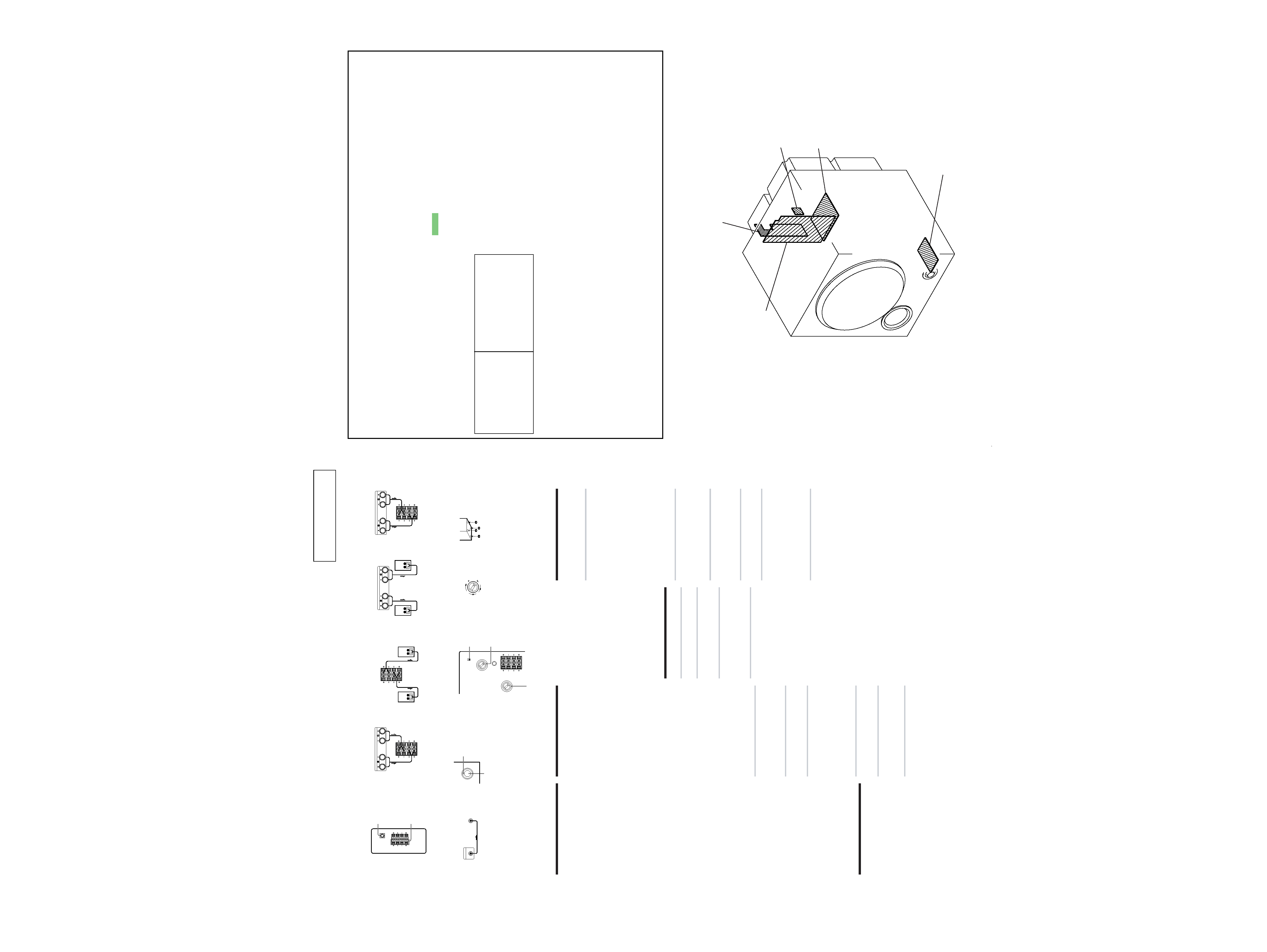
2-1. NOTE FOR PRINTED WIRING BOARDS AND SCHEMATIC DIAGRAMS
CONTROL board
POWER TRANS board
SWITCH board
INPUT CONTROL board
MAIN board
2-2. CIRCUIT BOARDS LOCATION
SECTION 2
DIAGRAMS
SECTION 1
GENERAL
LOCATION OF CONTROL
This section is extracted
from instruction manual.
INPUT
SPEAKER IN
IN
OUT
INPUT
L
SPEAKER
L
R
R
Amplifier
This subwoofer
IN
OUT
L
SPEAKER
L
R
R
SPEAKER
This subwoofer
IN
OUT
L
SPEAKER
L
R
R
Front Speaker (R)
Front Speaker (L)
SPEAKER A
IN
OUT
L
SPEAKER
L
R
R
SPEAKER B
A
1
B
2
1
C
2
LEVEL
PHASE
E
POWER
1
F
Amplifier
This subwoofer
MONO OUT
INPUT
D
CUT OFF FREQ
Front Speaker (R)
Front Speaker (L)
Amplifier
This subwoofer
Amplifier
CUT OFF FREQ
200Hz
NORMAL
REVERSE
50Hz
PHASE
MAX
MIN
LEVEL
IN
OUT
L
L
R
R
4
3
2
1
50Hz
200Hz
75Hz
120Hz 150Hz
100Hz
2
G
Foot pads
POWER indicator
Precautions
On safety
· Before operating the subwoofer, be sure that the
operating voltage of your subwoofer is identical with
that of your local power supply.
· Unplug the subwoofer from the wall outlet if it is not to
be used for an extended period of time. To disconnect
the cord, pull the cord by grasping the plug. Never
pull the cord itself.
· Should any liquid or solid object fall into the
subwoofer, unplug the subwoofer and have the
subwoofer checked by qualified personnel before
operating it any further.
· AC power cord must be changed only at the qualified
service shop.
When turning on or off an amplifier or other
equipment
Lower the volume of the amplifier to minimum.
To avoid damaging the subwoofer
· Be careful in setting the volume control of the amplifier
to avoid an excessive input power.
· Do not attempt to open the enclosure or remold
speaker units and networks.
In case color irregularity is observed on the
nearby TV screen
With the magnetically shielded type of the speaker
system, the speakers can be installed near a TV set.
However, color irregularity may still be observed on the
TV screen depending on the type of your TV set.
If color irregularity is observed...
t Turn off the TV set once, then turn it on after 15 to
30 minutes.
If color irregularity is observed again...
t Place the speakers further apart from the TV set.
When howling occurs
Relocate the speaker or turn down the volume of the
amplifier.
On installation
· Do not install the subwoofer near heat sources such as
radiators or air ducts, or in a place subject to direct
sunlight, excessive dust, mechanical vibration or shock.
· Good ventilation is essential to prevent internal heat
build-up in the subwoofer. Place the subwoofer in a
location with adequate air circulation. Do not place the
subwoofer on a soft surface.
· Use caution when placing the speaker on a specially
treated (waxed, oiled, polished, etc.) floor, as staining
or discoloration may result.
On cleaning the cabinet
Clean the cabinet with a soft cloth lightly moistened with
water. Do not use any type of abrasive pad, scouring
powder or solvent such as alcohol or benzine.
If you have any questions or problems concerning your
subwoofer that is not covered in this manual, please
consult your nearest Sony dealer.
Installation
Since the human ear cannot detect the direction and
position where the bass sound being reproduced by a
subwoofer (below 200 Hz) comes from, you can install
the subwoofer wherever you like in your room. To
obtain a better bass reproduction, we recommend you
to install the subwoofer on a solid floor where the
resonance is unlikely to occur.
Notes
·Always install the subwoofer vertically, keeping a few
centimeters away from the wall.
· Do not place an object on the subwoofer or sit on it.
· If the subwoofer is installed in the center of a room, the
bass could be extremely weakened. This is due to the
influence of the standing wave of the room. If this
happens, move the subwoofer away from the center of
a room or eliminate the cause of the standing wave, by
installing a bookshelf on the wall, etc.
Hooking Up the System
Overview
Use the INPUT jacks or the SPEAKER IN terminals of the
subwoofer when you connect the amplifier.
· If your amplifier has one of the following types of
output jacks, connect the INPUT jack and the
amplifier's jack using the supplied audio connecting
cord.
-- MONO OUT jack
--MIX OUT jack
-- SUBWOOFER output jack(s)
-- SUPER WOOFER output jack(s)
· If your amplifier does not have the above mentioned
output jacks, connect the speaker terminals of the
amplifier to the SPEAKER IN terminals instead. (A)
Before you get started
· Turn off the power of the amplifier and the subwoofer
before making any connection.
· Use the audio connecting cords that are supplied to
the respective equipment. If there are not enough
audio connecting cords to make the necessary
connections, you need to purchase some optional
audio connecting cords.
· Be sure to make connections firmly to avoid noise.
· Connect the AC power cord from the subwoofer to
a wall outlet.
· You cannot connect the CENTER output jack for use
with Dolby Pro Logic function to the subwoofer.
Bass sound is not output with some Dolby Pro Logic
modes.
Connecting to an amplifier with a
single set of speaker terminals (B)
If your amplifier is equipped with a single set of speaker
terminals, connect the subwoofer to the amplifier, and
then connect the front speakers to the subwoofer.
Hookups
1 Connect the subwoofer to the amplifier.
Connect the SPEAKER IN terminals of the
subwoofer to the amplifier's speaker
terminals with the speaker cords. Be sure to
connect both L and R channels.
2 Connect the front speakers to the subwoofer.
Connect the speakers to the SPEAKER OUT
terminals of the subwoofer.
Connecting to an amplifier with
double (A+B) sets of speaker
terminals (C)
If your amplifier has double (A+B) sets of speaker
terminals, connect both the subwoofer and the front
speakers to the amplifier.
Hookups
1 Connect the front speakers to the amplifier.
Connect the speakers to your amplifier's
SPEAKER A terminals.
2 Connect the subwoofer to the amplifier.
Connect the SPEAKER IN terminals of the
subwoofer to the amplifier's SPEAKER B
terminals using the supplied speaker cords.
When using the double (A+B) sets of speakers, make
sure that you select the "A+B" position with your
amplifier.
Note
When you are using SPEAKER A terminal (front
speaker) only or when the power of the amplifier is
turned off, turn down the volume or turn off the power
of the subwoofer. Otherwise, hum noise may be heard.
Connecting to an amplifier with a
special jack for a subwoofer
If your amplifier has a special jack for a subwoofer (such
as MONO OUT jack, MIX OUT jack, SUBWOOFER jack
or SUPER WOOFER jack), connect the INPUT jack of the
subwoofer to one of those jacks.
Hookups (D)
Connect the MONO OUT jack of your amplifier to the
INPUT jack of the subwoofer with the supplied audio
connecting cord.
Note
If the output level of your amplifier is not large enough,
the sound may not be loud enough. In this case, connect
the speaker terminals of the amplifier directly to the
SPEAKER IN terminals of the subwoofer.
Connecting the AC power cord
· Connect the AC power cord from the subwoofer and
from your amplifier to a wall outlet.
· Make sure that power to the subwoofer is turned off
before you plug in or unplug any power cord.
Listening to the Sound (E)
1 Turn on the amplifier and select the program
source.
2 Press POWER.
The subwoofer turns on and the POWER
indicator lights up in green.
3 Play the program source.
Adjust the VOLUME so that sound from the
front speakers is not distorted.
If it is distorted, the sound from the
subwoofer will also be distorted.
Notes
· Never set the amplifier's tone control (BASS, TREBLE,
etc.) or the equalizer output to a high level or input
sinewaves of 20 Hz to 50 Hz recorded on a
commercially-available test disc or special sound (bass
sound of electronic musical instrument, pop noise of
analog disc turntable, sound with abnormally
enhanced bass, etc.) in a high level to this unit. These
actions may cause damage to the speakers.
When a special disc containing abnormally enhanced
bass is played, noise may be output in addition to the
original sound. In such a case, reduce the sound level.
· The subwoofer output signal (DOLBY digital signal)
of the digital surround processor sold singularly is set
10 dB higher by Dolby laboratories Licensing
Corporation. In the case of using normally, adjust the
subwoofer level.
Adjusting the Sound (F)
You can adjust the sound of the subwoofer to suit the
sound of your front speakers. Reinforcing the bass sound
gives you a greater sense of atmosphere.
1 Adjust the cut-off frequency.
Turn the CUT OFF FREQ control, depending
on the reproduction frequencies of your front
speakers.
Refer to the following when adjusting.
1 Typical very small sized speakers: 5 7 cm
dia.
2 Typical small sized speakers: 8 15 cm dia.
3 Typical medium sized speakers: 16 24 cm
dia.
4 Typical large sized speakers: more than 25
cm dia.
To make the most of the low level converter
function of Dolby digital, turn the CUT OFF
FREQ as high as possible when playing back
the Dolby digital.
2 Adjust the volume level of the subwoofer.
Turn the LEVEL control so that you can hear
the bass sound a little more than before. To
increase the volume, turn the LEVEL control
clockwise. To reduce the volume, turn the
LEVEL control counterclockwise.
3 Play your favorite song and movie.
Male vocal tunes and voice containing bass
sounds are most suitable for adjustment.
Turn the volume for front speakers to the
same level as usual.
4 Select the phase polarity.
Use the PHASE selector to select the phase
polarity.
5 Repeat steps 1 to 4 to adjust for your
preference.
Once you have adjusted the subwoofer to the
settings you want, use the VOLUME control
on the amplifier to adjust the volume of the
subwoofer with that of the other speakers.
You don't need to adjust the subwoofer
settings when you change the volume level
of the amplifier.
Notes
· If the sound distorts when you turn on the bass
reinforcement from your amplifier (such as, DBFB,
GROOVE, the graphic equalizer, etc.), turn off the bass
reinforcement and adjust the sound.
· Do not turn the volume of the subwoofer to maximum.
Doing so may weaken the bass sound. Moreover,
extraneous noise may be heard.
· Selecting NORMAL or REVERSE with the PHASE
selector reverses the polarity and may provide better
bass reproduction in certain listening environments
(depending on the type of front speakers, the position
of the subwoofer and the adjustment of the cut-off
frequency). It may also change the expanse and
tightness of sound, and effect the feeling of the sound
field. Select the setting that provides the sound you
prefer when listening in your normal listening position.
Setting the speaker (G)
To prevent speaker vibration or movement while
listening, attach the supplied foot pads to the speaker.
THIS NOTE IS COMMON FOR PRINTED WIRING
BOARDS AND SCHEMATIC DIAGRAMS.
(In addition to this, the necessary note is printed
in each block.)
For schematic diagrams.
Note:
· All capacitors are in µF unless otherwise noted. pF: µµF
50 WV or less are not indicated except for electrolytics
and tantalums.
· All resistors are in and 1/4 W or less unless otherwise
specified.
·
f
: internal component.
· C : panel designation.
For printed wiring boards.
Note:
· X : parts extracted from the component side.
· Y : parts extracted from the conductor side.
·
: Pattern from the side which enables seeing.
·Abbreviation
CND : Canadian model.
MY
: Malaysia model.
SP
: Singapore model.
· A : B+ Line.
· B : B Line.
·Voltages are dc with respect to ground under no-signal
(detuned) conditions.
no mark : Power on
·Voltages are taken with a VOM (Input impedance 10 M).
Voltage variations may be noted due to normal produc-
tion tolerances.
· Signal path.
F
: AUDIO
·Abbreviation
CND : Canadian model.
MY
: Malaysia model.
SP
: Singapore model.
TW
: Taiwan model.
Note:
The components identi-
fied by mark 0 or dotted
line with mark 0 are criti-
cal for safety.
Replace only with part
number specified.
Note:
Les composants identifiés par
une marque 0 sont critiques
pour la sécurité.
Ne les remplacer que par une
piéce por tant le numéro
spécifié.
4
4
SA-WM250
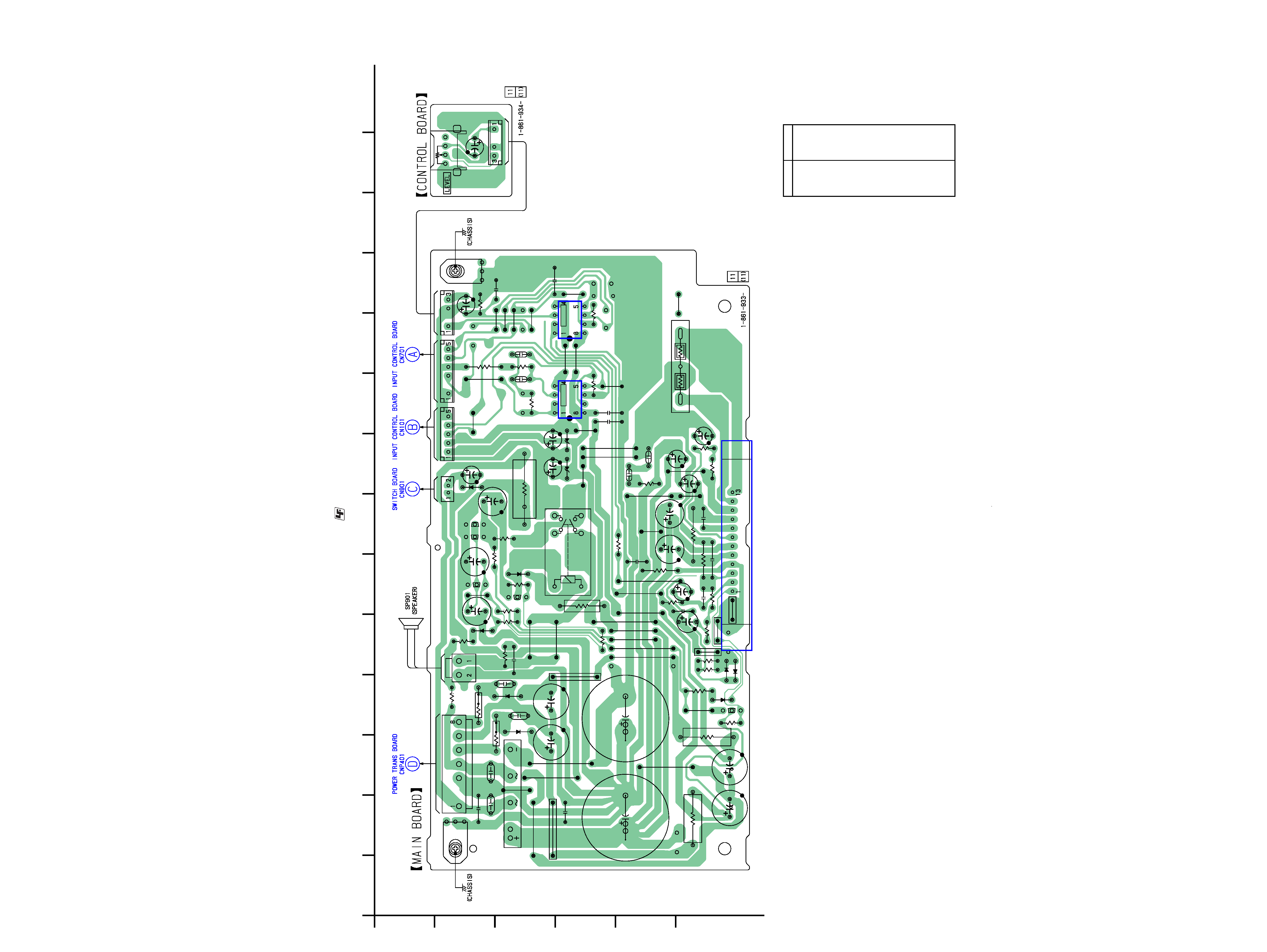
2-3. PRINTED WIRING BOARDS -- MAIN SECTION -- · Refer to page 3 for Circuit Boards Location.
: Uses unleaded solder.
1
A
B
C
D
E
F
23456789
10
11
12
13
14
CN402
CN301
IC301
RY301
C401
C402
C405
C407
C408
D402
D403
Q501
Q502
Q503
Q504
D501
C501
C502
C503
R403
R404
C308
C306
C307
R307
C302
R301
R302
R401
R402
D304
R311
R312
C309
C310
R502
R503
JW102
JW116
C303
JW114
JW115
R308
D401
D301
JW106
R309
R303
C301
JW301
R508
Q505
R506
D502
R507
JW126
JW127
JW501
C312
R505
R304
R501
G1
G2
R500
C409
C410
C313
JW128
R313
R315
D302
C406
R207
C203
C204
R208
R210
R205
R215
R216
C210
R217
C305
C304
R504
C601
D602
R601
D205
D206
C205
C206
JW123
JW105
IC203
IC202
JW107
CN201
JW108
JW132
JW109
R305
C311
CN202
JW110
R314
JW111
JW129
R306
JW101
CNP111
C404
JW404
JW403
JW103
JW104
C211
C209
JW117
JW118
R211
JW120
JW121
JW131
JW122
JW133
JW134
JW119
R310
C403
JW135
C316
C317
C318
C314
CN204
JW124
JW125
C411
C412
R317
JW130
JW112
CNP801
C801
RV801
(Page 6)
(Page 5)
(Page 5)
(Page 6)
D205
D-8
D206
D-8
D301
F-4
D302
F-4
D304
C-6
D401
C-3
D402
C-4
D403
C-4
D501
B-5
D502
F-4
D602
B-8
IC202
D-9
IC203
D-10
IC301
F-7
Q501
B-6
Q502
C-6
Q503
B-7
Q504
B-7
Q505
F-4
· Semiconductor
Location
Ref. No.
Location
55
SA-WM250
1
A
B
C
D
E
F
23456789
10
11
12
13
14
IC201
IC701
D204
C101
C201
S701
RV701
C701
C702
C703
C704
C705
C706
CN701
CN101
JW207
D203
JW208
J101
JW210
TM101
R103
R701
D202
D201
JW204
JW205
JW209
JW701
JW702
JW206
R202
R201
R203
R708
R707
R706
R704
R705
R702
R102
R104
R101
R106
R105
R108
R109
R107
R703
R110
R204
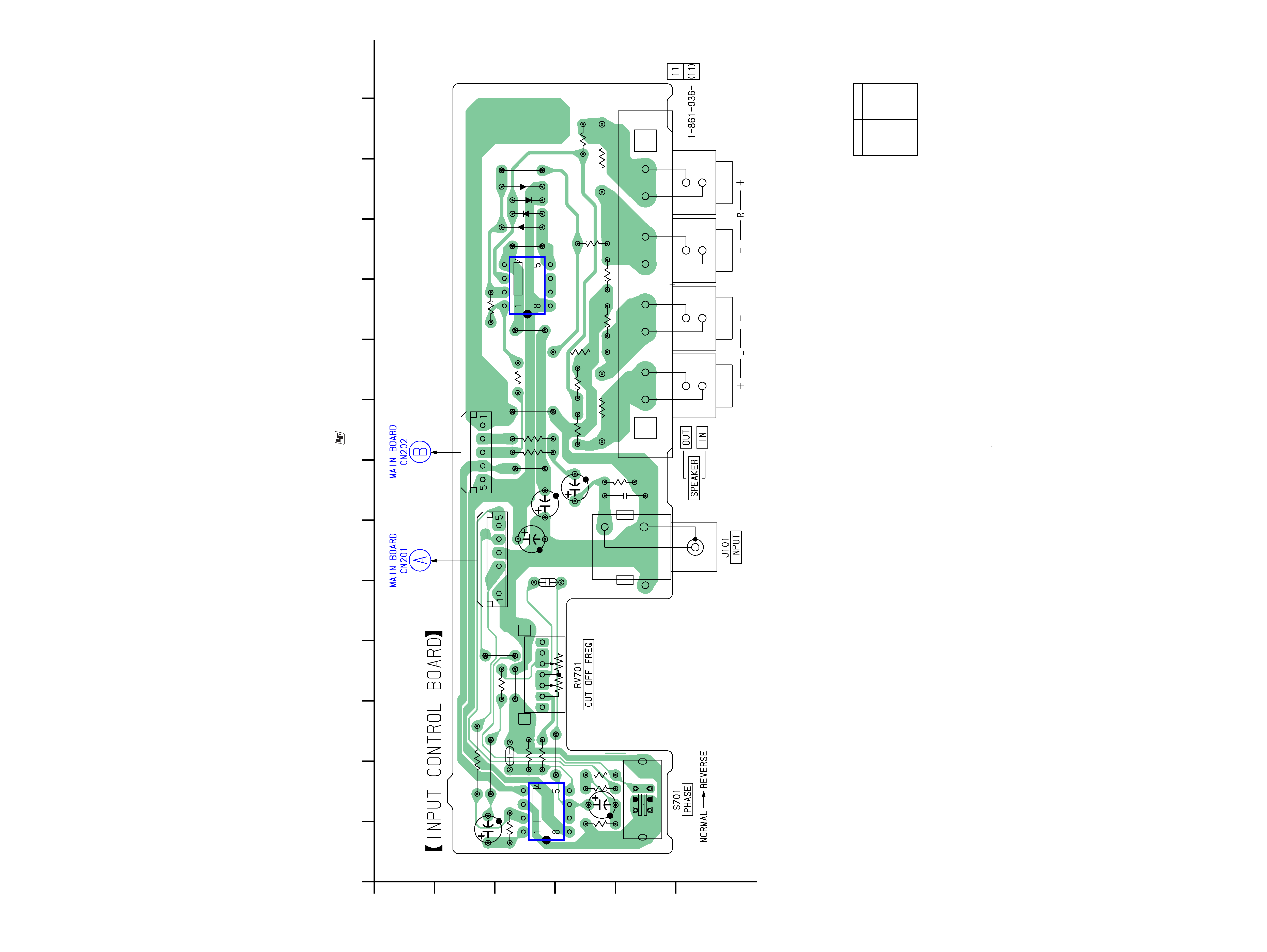
2-4. PRINTED WIRING BOARD -- INPUT CONTROL SECTION -- · Refer to page 3 for Circuit Boards Location.
: Uses unleaded solder.
(Page 4)
(Page 4)
D201
C-12
D202
C-12
D203
C-11
D204
C-12
IC201
C-10
IC701
C-2
· Semiconductor
Location
Ref. No.
Location