SERVICE MANUAL
ACTIVE SUPER WOOFER
US Model
SA-W303/W305
Canadian Model
AEP Model
UK Model
SA-W305
E Model
SA-W11/W305
Australian Model
SA-W305
Chinese Model
SA-W11
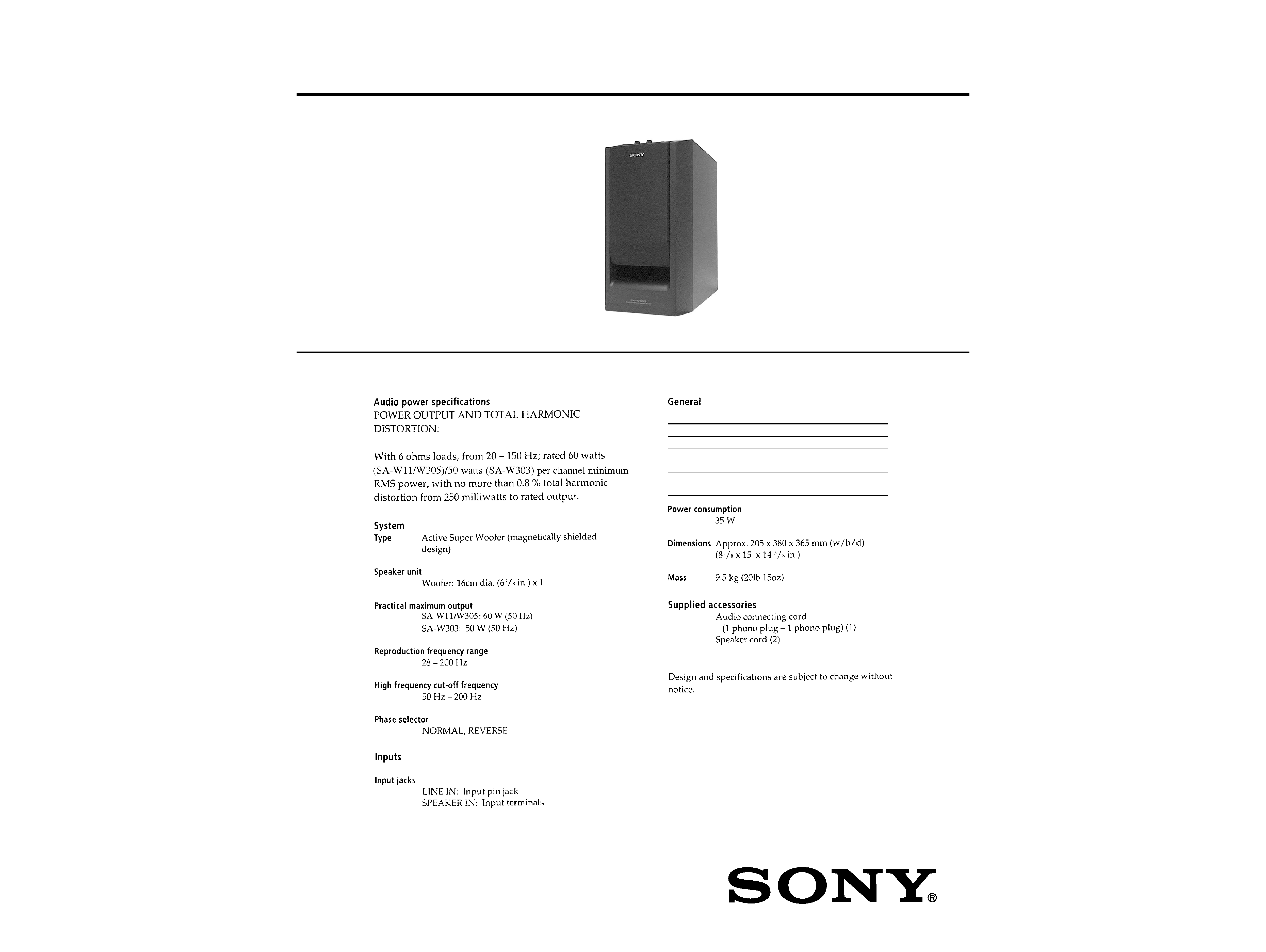
SPECIFICATIONS
SA-W11/W303/W305
Photo: SA-W305
Power requirements
Where purchased
Power requirements
US, Canadian model
120 V AC, 60 Hz
AEP, UK, German,
220 230 V AC, 50/60 Hz
East European model
E, Australian, Chinese,
110 120/220 240 V AC,
Malaysia, Singapore model
adjustable, 50/60 Hz
Ver 1.1 2001.11
9-922-813-12
Sony Corporation
2001K0500-1
Home Audio Company
C
2001.11
Published by Sony Engineering Corporation
2
ATTENTION AU COMPOSANT AYANT RAPPORT
À LA SÉCURITÉ!
LES COMPOSANTS IDENTIFIÉS PAR UNE MARQUE 0
SUR LES DIAGRAMMES SCHÉMATIQUES ET LA LISTE
DES PIÈCES SONT CRITIQUES POUR LA SÉCURITÉ
DE FONCTIONNEMENT. NE REMPLACER CES COM-
POSANTS QUE PAR DES PIÈCES SONY DONT LES
NUMÉROS SONT DONNÉS DANS CE MANUEL OU
DANS LES SUPPLÉMENTS PUBLIÉS PAR SONY.
SAFETY-RELATED COMPONENT WARNING!!
COMPONENTS IDENTIFIED BY MARK 0 OR DOTTED
LINE WITH MARK 0 ON THE SCHEMATIC DIAGRAMS
AND IN THE PARTS LIST ARE CRITICAL TO SAFE
OPERATION. REPLACE THESE COMPONENTS WITH
SONY PARTS WHOSE PART NUMBERS APPEAR AS
SHOWN IN THIS MANUAL OR IN SUPPLEMENTS PUB-
LISHED BY SONY.
SAFETY CHECK-OUT
After correcting the original service problem, perform the follow-
ing safety check before releasing the set to the customer:
Check the antenna terminals, metal trim, "metallized" knobs,
screws, and all other exposed metal parts for AC leakage.
Check leakage as described below.
LEAKAGE TEST
The AC leakage from any exposed metal part to earth ground and
from all exposed metal parts to any exposed metal part having a
return to chassis, must not exceed 0.5 mA (500 microampers.).
Leakage current can be measured by any one of three methods.
1. A commercial leakage tester, such as the Simpson 229 or RCA
WT-540A. Follow the manufacturers' instructions to use these
instruments.
2. A battery-operated AC milliammeter. The Data Precision 245
digital multimeter is suitable for this job.
3. Measuring the voltage drop across a resistor by means of a
VOM or battery-operated AC voltmeter. The "limit" indica-
tion is 0.75 V, so analog meters must have an accurate low-
voltage scale. The Simpson 250 and Sanwa SH-63Trd are ex-
amples of a passive VOM that is suitable. Nearly all battery
operated digital multimeters that have a 2 V AC range are suit-
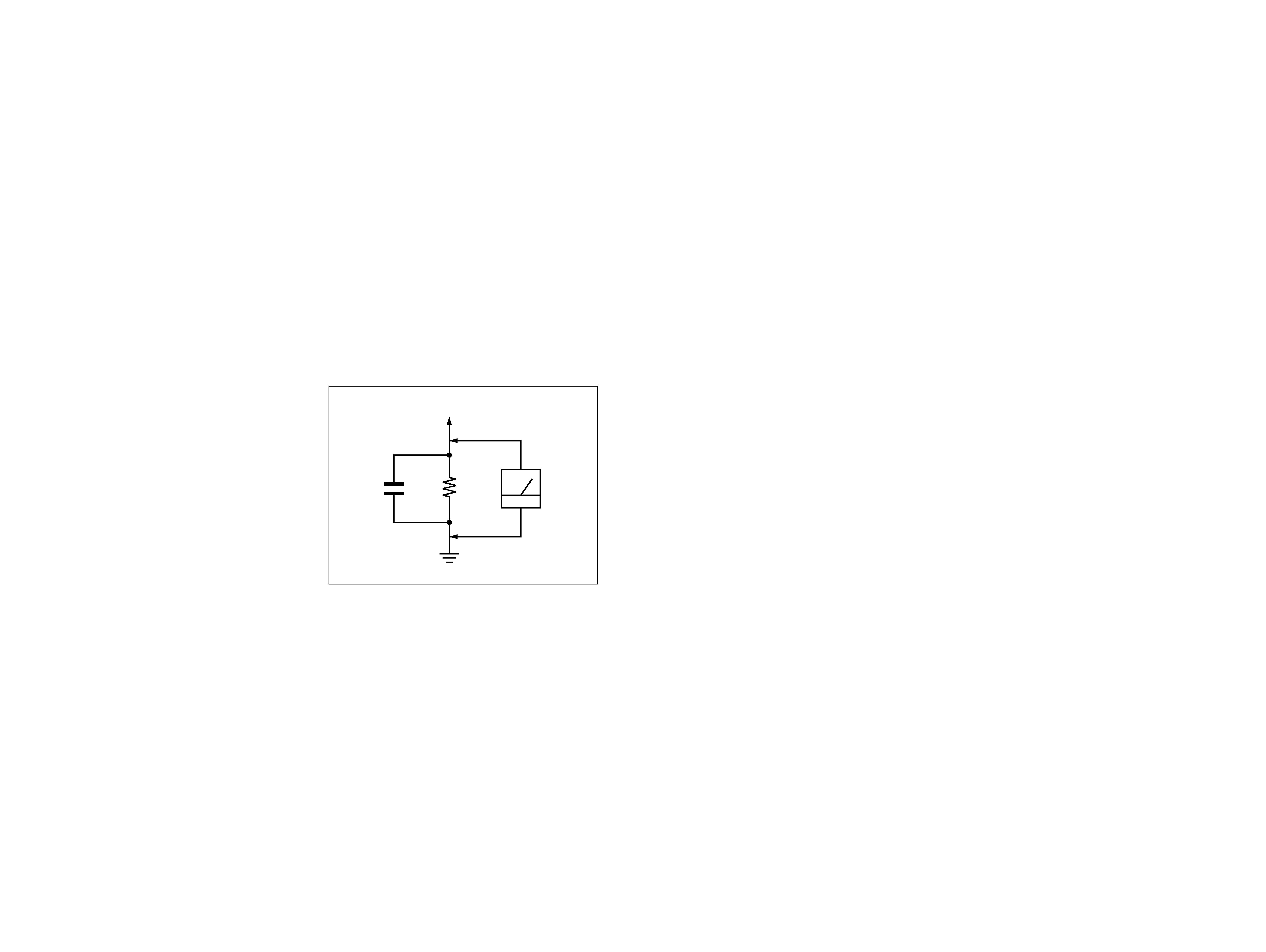
able. (See Fig. A)
Fig. A.
Using an AC voltmeter to check AC leakage.
1.5 k
0.15
µF
AC
voltmeter
(0.75 V)
To Exposed Metal
Parts on Set
Earth Ground
1
2
3
4
5
6
7
8
OVER LOAD DET
F/F
OFFSET DET
LATCH/
AUTORESET
VCC ON
MUTE
AC OFF
DET
VCC
SECTION 1
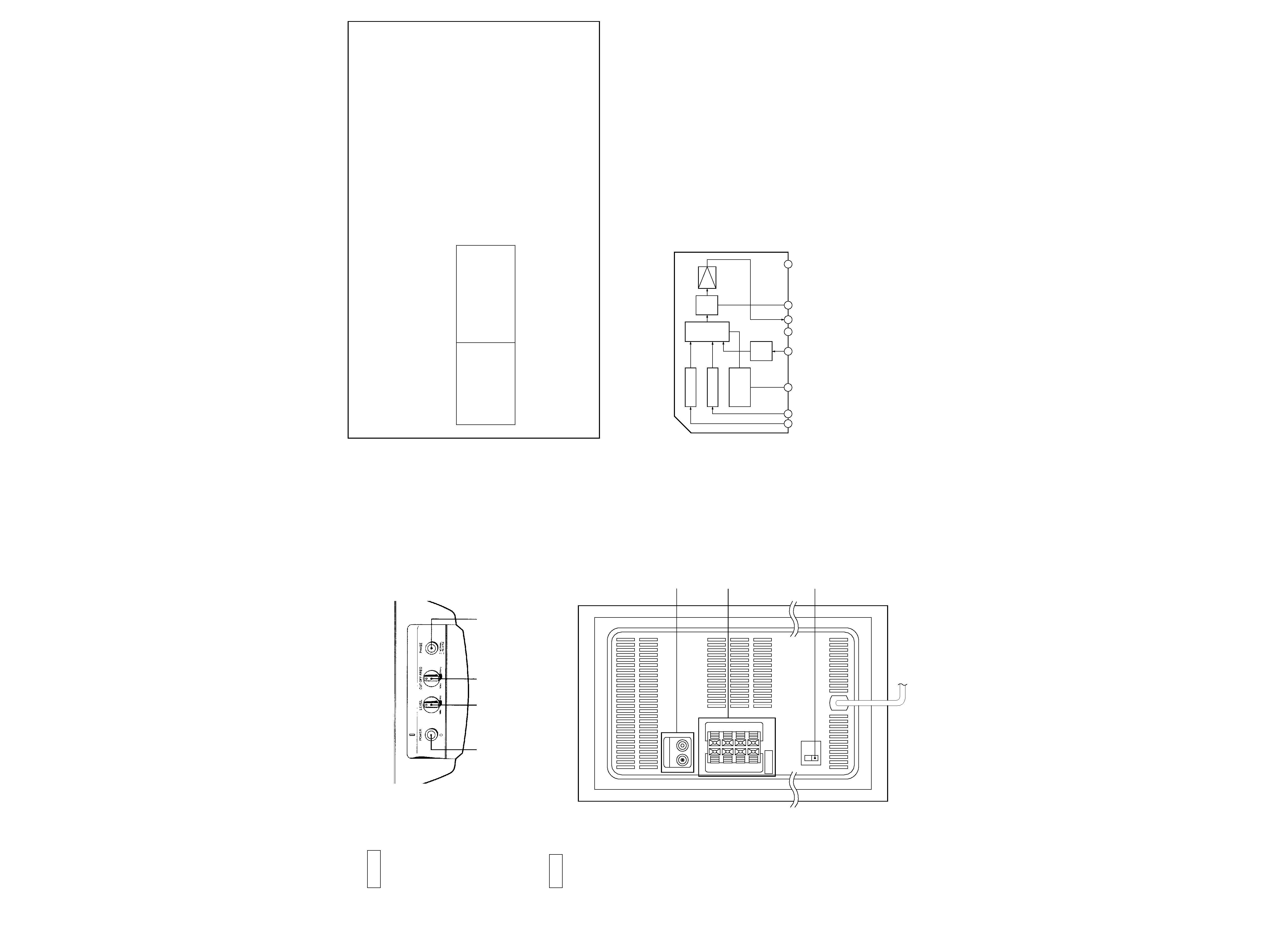
GENERAL
· Location of Controls
REAR
· IC Block Diagram
IC302 µPC1237HA
SECTION 2
DIAGRAMS
LINE
IN
OUT
IN
OUT
+
+
+
+
SPEAKER
L
R
L
R
LINE
IN/OUT jack
SPEAKER IN/OUT
terminal
VOLTAGE SELECTOR switch
(E, Australian, Singapore,
Chinese, Malaysia)
FRONT
3
4
POWER
switch
LEVEL
knob
CUT OFF FREQ
knob
PHASE
button
Note on Schematic Diagram:
· All capacitors are in µF unless otherwise noted. pF: µµF
50 WV or less are not indicated except for electrolytics
and tantalums.
· All resistors are in
and 1/4 W or less unless otherwise
specified.
· 2 : nonflammable resistor.
· C : panel designation.
Note on Printed Wiring Boards:
· X : parts extracted from the component side.
Abbreviation:
AUS
: Australian
CH
: Chinese
CND : Canadian
EE
: East European
G
: German
MY
: Malaysia
SP
: Singapore
· U : B+ Line.
· V : B Line.
· Voltages are dc with respect to ground under no-signal
conditions.
· Voltages are taken with a VOM (Input impedance 10 M
).
Voltage variations may be noted due to normal produc-
tion tolerances.
· Signal path.
F
THIS NOTE IS COMMON FOR PRINTED WIRING BOARDS AND SCHEMATIC DIAGRAMS.
(In addition to this, the necessary note is each block.)
Note:
The components identi-
fied by mark 0 or dotted
line with mark 0 are criti-
cal for safety.
Replace only with part
number specified.
Note:
Les composants identifiés par
une marque 0 sont critiques
pour la sécurité.
Ne les remplacer que par une
piéce por tant le numéro
spécifié.
Ref. No.
Location
D301
B-7
D302
B-7
D303
A-8
D401
C-4
D402
D-4
IC101
C-9
IC102
D-8
IC302
A-9
IC401
C-7
IC402
D-7
Q101
C-10
Q401
A-9
5
6
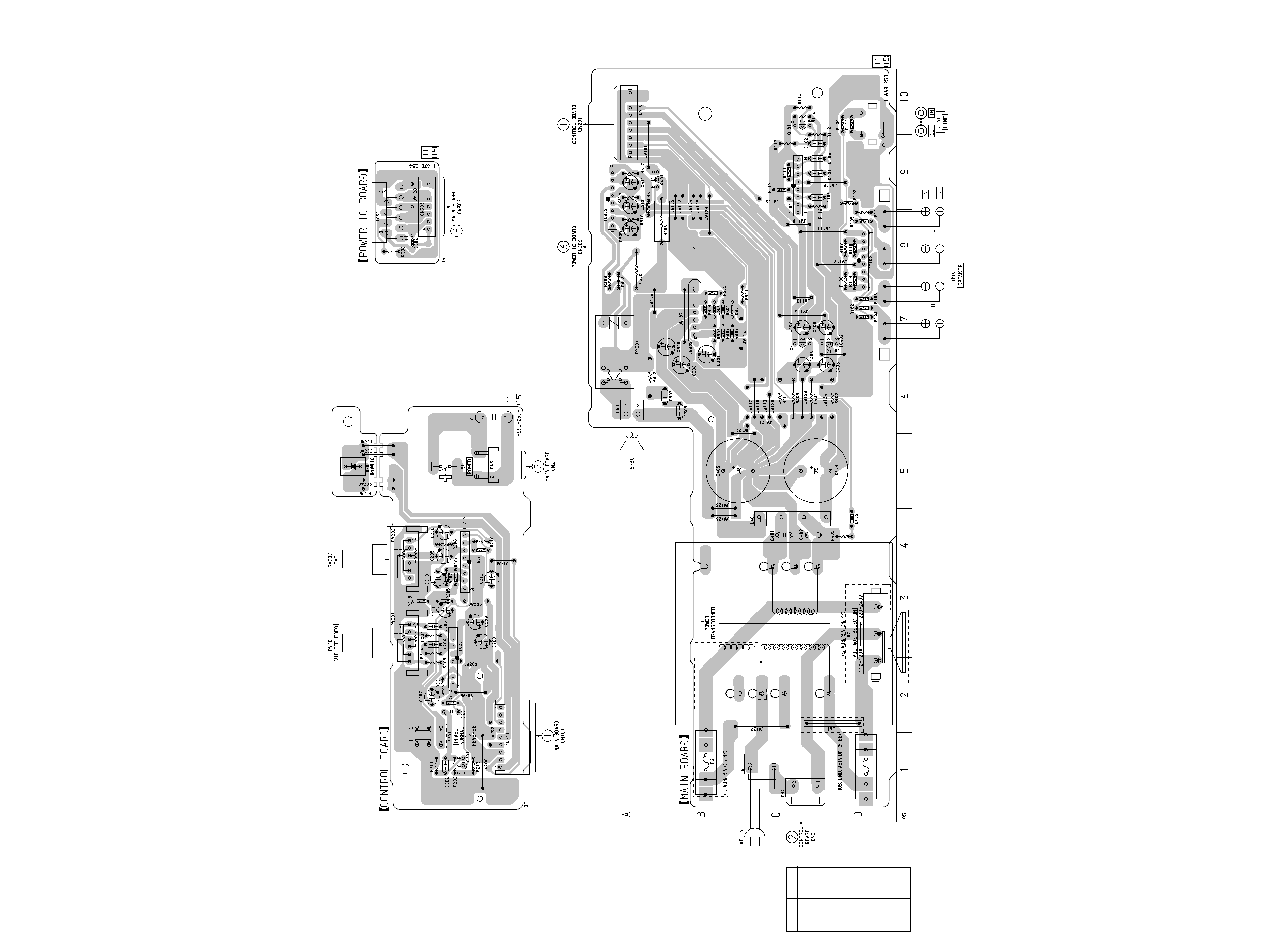
SA-W11/W303/W305
2-1.
PRINTED WIRING BOARDS
· See page 4 for Note.
· Semiconductor
Location
(MAIN Board)
SA-W11/W303/W305
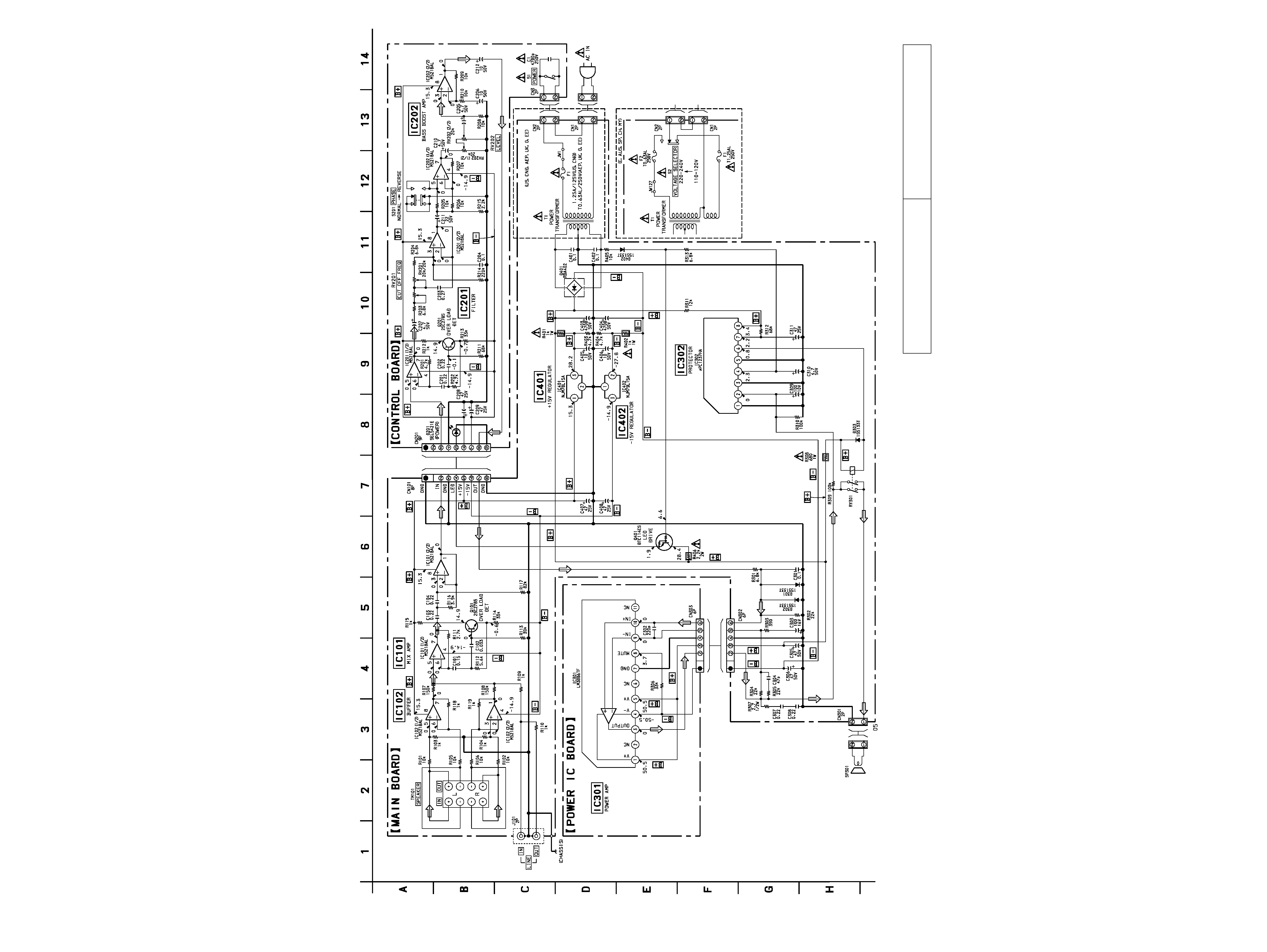
2-2.
SCHEMATIC DIAGRAM
· See page 4 for Note.
· See page 4 for IC Block Diagram.
7
8
The components identified by mark 0 or dotted
line with mark 0 are critical for safety.
Replace only with part number specified.
Les composants identifiés par une marque 0 sont
critiques pour la sécurité.
Ne les remplacer que
par une piéce portant le numéro spécifié.