SPECIFICATIONS
SERVICE MANUAL
SAT-W60 RM-Y804
U.S. Model
INTERNET TERMINAL
Terminals:
Dimensions:
(w/h/d)
Weight:
Video In (2)
Video Out (2)
Audio (R/L) In (2)
Audio (R/L) Out (2)
S-Video In (1) /Out (1)
Tel Line (1)
Microphone In (1)
Printer Port (DB25) (1)
VCR Control (1)
Digital Audio Out (1)
USB Port (2)
Satellite In (2)
CH3-CH4 Switch (1)
VHF/UHF In/Out (1)
AC In (1)
430 x 70 x 290 mm (w/h/d)
(17 x 23/4 x 111/2 inches)
Approx. 4.3 kg (9.4 lbs.)
Power Requirements:
Power Consumption:
Supplied Accessories:
Optional Accessories:
AC 120V
90 W Max
Remote Control RM-Y804 (1)
Size AA Batteries (2)
AC Power Cord (1)
A/V (Audio/Video) Cable (1)
Telephone Cable (1)
S-Video Cable (1)
T Splitter (1)
Coaxial Cable (1)
IR Blaster (1)
Wireless Keyboard KI-W250 (1)
Access Card (1)
Local Antenna ANJ-AA1
Installation Kit ANJ-DS2
Amplifier EAC-DA1
Diplexer EAC-DD1
Voltage Switch EAC-DV2
Satellite Dish Antenna: SAN-24MD1
SAN-18D4
Design and specifications are subject to change without notice.
SAT-W60
RM-Y804
9-965-897-02
-- 2 --
SAT-W60
SAFETY CHECK-OUT
After correcting the original service problem, perform the
following safety checks before releasing the set to the
customer:
Leakage Test
The AC leakage from any exposed metal part to earth ground
and from all exposed metal parts to any exposed metal part
having a return to chassis, must not exceed 0.5 mA (500
microampere). Leakage current can be measured by any one
of three methods.
1. A commercial leakage tester, such as the Simpson 229 or
RCA WT-540A. Follow the manufacturers' instructions to use
these instructions.
2. A battery-operated AC milliammeter. The Data Precision 245
digital multimeter is suitable for this job.
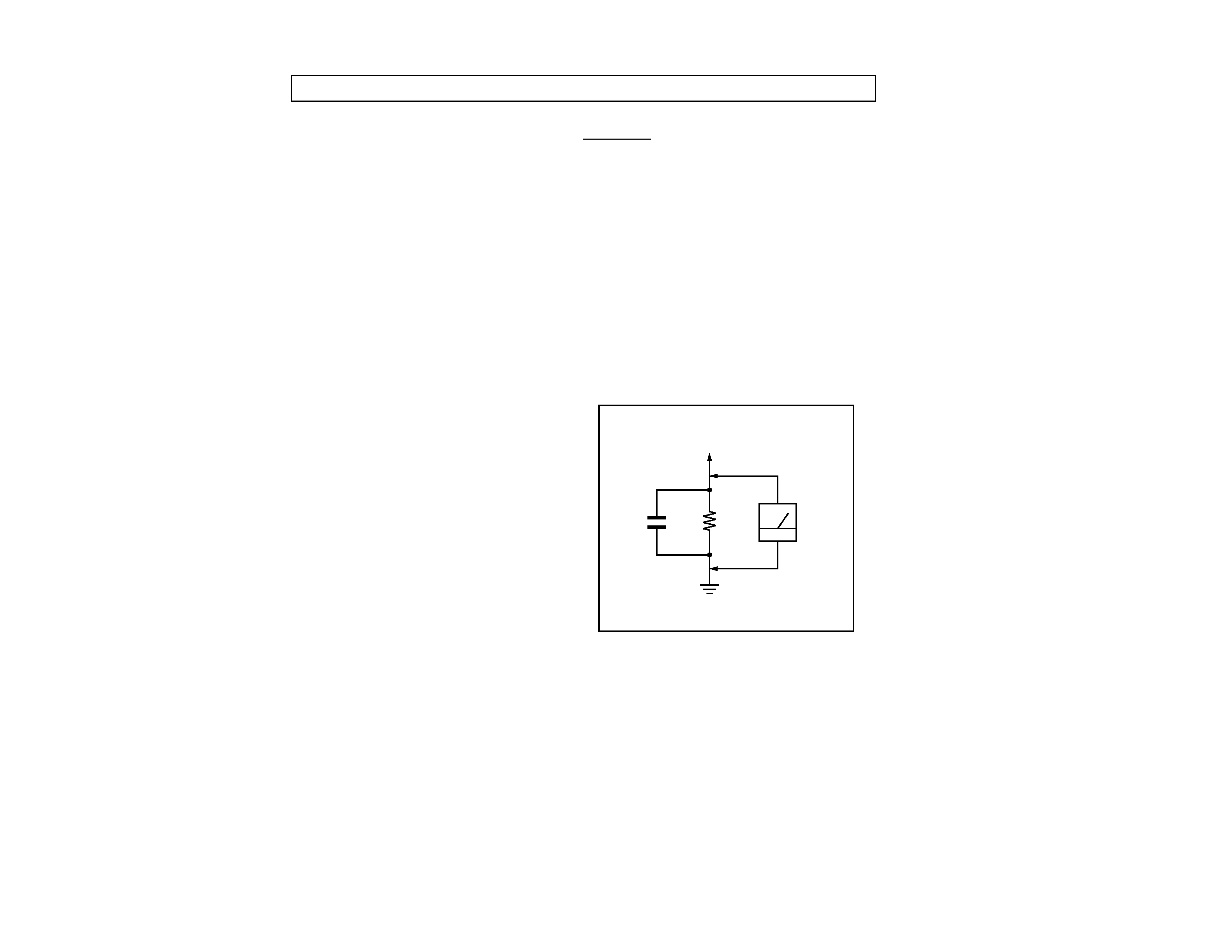
3. Measuring the voltage drop across a resistor by means of a
VOM or battery-operated AC voltmeter. The "limit" indication
is 0.75 V, so analog meters must have an accurate low voltage
scale. The Simpson's 250 and Sanwa SH-63Trd are
examples of passive VOMs that are suitable. Nearly all battery
operated digital multimeters that have a 2V AC range are
suitable. (See Figure A)
1. Check the area of your repair for unsoldered or poorly-
soldered connections. Check the entire board surface
for solder splashes and bridges.
2. Check the interboard wiring to ensure that no wires are
"pinched" or contact high-wattage resistors.
3. Check that all control knobs, shields, covers, ground
straps, and mounting hardware have been replaced. Be
absolutely certain that you have replaced all the insulators.
4. Look for unauthorized replacement parts, particularly
transistors, that were installed during a previous repair.
Point them out to the customer and recommend their
replacement.
5. Look for parts which, though functioning, show obvious
signs of deterioration. Point them out to the customer
and recommend their replacement.
6. Check the line cords for cracks and abrasion.
Recommend the replacement of any such line cord to
the customer.
7. Check the B+ and HV to see if they are specified values.
Make sure your instruments are accurate; be suspicious
of your HV meter if sets always have low HV.
8. Check the antenna terminals, metal trim, "metallized"
knobs, screws, and all other exposed metal parts for AC
Leakage. Check leakage as described below.
1.5 k
0.15 µF
AC
Voltmeter
(0.75 V)
To Exposed Metal
Parts on Set
Earth Ground
Figure A
-- 3 --
SAT-W60
TABLE OF CONTENTS
Section
Title
Page
Safety Check Out Instructions ........................................................................................................ 2
1.
GENERAL ................................................................................................................................... 4
2.
DISASSEMBLY
2-1. Upper Cover Removal ............................................................................................ 10
2-2. Hard Drive Removal ................................................................................................. 10
3.
SYSTEM SELF TEST .............................................................................................................. 11
4.
DIAGRAMS
4-1. Block Diagram ......................................................................................................... 12
4-2. Schematic Diagrams ................................................................................................ 13
5.
EXPLODED VIEWS
5-1. Front Panel View ..................................................................................................... 53
5-2. Rear View ................................................................................................................ 54
5-3. SAN-18D4 ............................................................................................................... 55
5-4. SAN-24MD1 ............................................................................................................ 55
6. ELECTRICAL PARTS LIST .......................................................................................................... 56
--
4
--
SA
T-W
60
The instructions mentioned here are partial abstracts from the Operating Instruction Manual.
The page numbers shown reflect those of the Operating Instruction Manual.
SECTION 1
GENERAL
Satellite Receiver
10
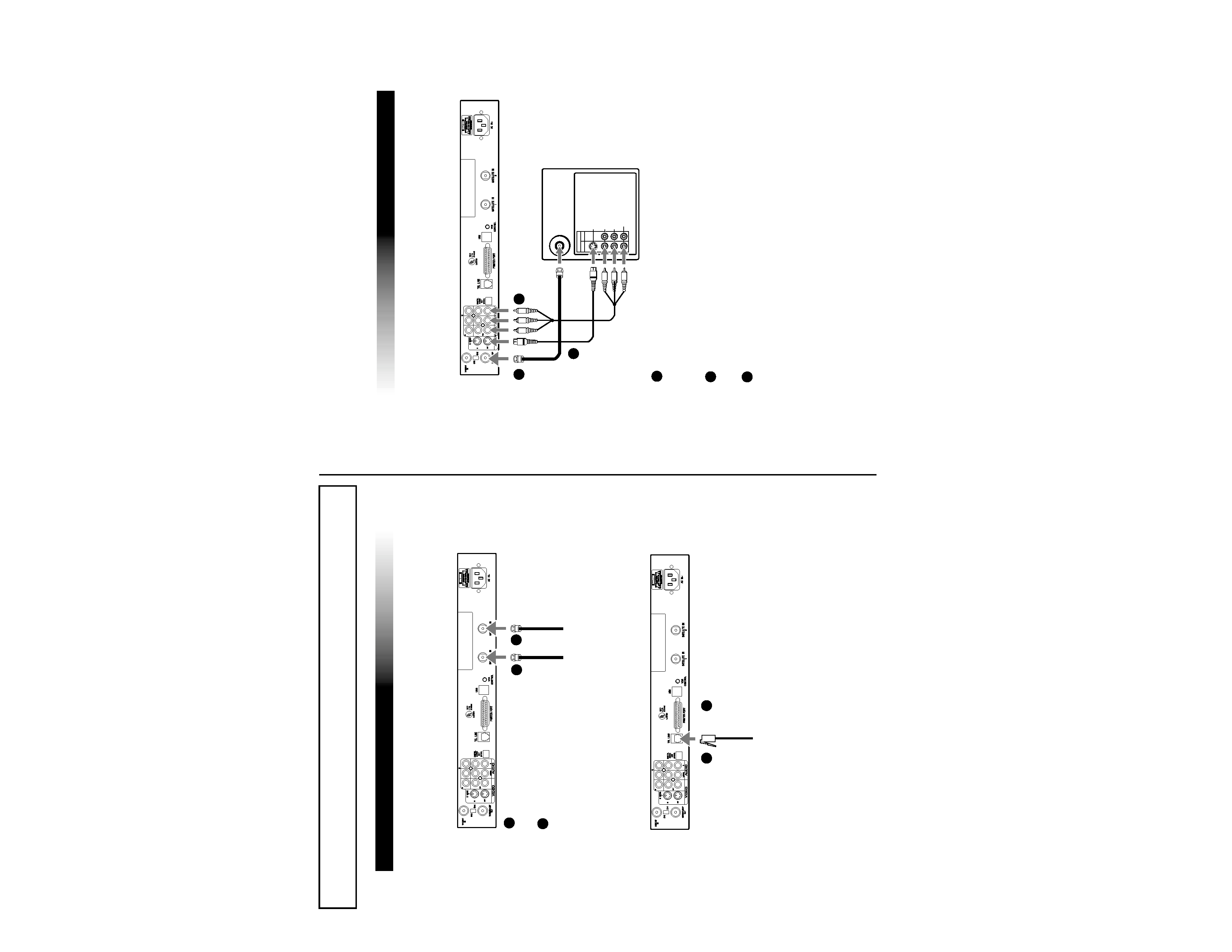
Step 1: Connecting the Antenna
Step 2: Connecting Your Phone Line
Satellite Receiver
Connect the SATELLITE IN jack
to your Satellite Dish Antenna
using RG-6 coaxial cable.
Connect the 2nd signal if you
have Dual LNB. Advance Set
Up for dual output.
1
1
2
2
Satellite Receiver
Connect the TELEPHONE
LINE jack to a telephone
line wall jack using the
supplied telephone cord.
1
1
Connecting Your Satellite Receiver
11
Step 3: Connecting Your TV Set
VHF / UHF
AUDIO
L
R
(MONO)
VIDEO
IN
VIDEO 1 VIDEO 2
TV
S VIDEO
Satellite Receiver
1a
1b
1c
If your TV has A/V input jacks
Connect the VIDEO OUT jacks on your Satellite Receiver to the
A/V input jacks on your TV using the supplied A/V cable. (Be sure to match the
colors on the jacks with the colored plugs on the A/V cable.) If your TV has only
one audio input, connect it to the L(MONO) jack on the Satellite Receiver.
If your TV has an S-Video input
Use an S-Video cable instead of the yellow video connection. S-Video cable is
supplied.
If your TV does not have A/V jacks
Connect the VHF/UHF OUT jack to the VHF/UHF input jack on your TV using
coaxial cable. Set the CH3/CH4 switch to the channel that does not carry off-air
broadcasts in your area.
1a
1b
1c
Note
With this connection, your input source
is channel 3 or channel 4 depending on
how you set the CH3/CH4 switch on the
Satellite Receiver.
--
5
--
SA
T-W
60
Satellite Receiver
12
Step 4: Connecting the AC Power
Step 5: Checking the Access Card
Step 6: Activating Your Service
After checking the DIRECTV Access Card and your Satellite Dish Antenna is installed,
you are ready to begin enjoying service.
Call DIRECTV at 1-800-DIRECTV (347-3288) to begin digital satellite programming.
For DIRECTV and UltimateTV operational instructions, please refer to the User Guide.
Satellite Receiver
AC Power Cord
to power outlet
After all other connections are
complete, connect the AC Power Cord
to the Satellite Receiver. Then connect
the AC Power Cord to a power outlet.
1
1
Satellite Receiver
1
1
Open the access door by applying gentle pressure to the latch and releasing.
Make sure the DIRECTV Access Card is firmly inserted into the front left hand
slot of the Satellite Receiver. After the DIRECTV Access Card is inserted
(correctly), DO NOT remove it unless instructed to do so by your service
provider.
Connecting Your Satellite Receiver
13
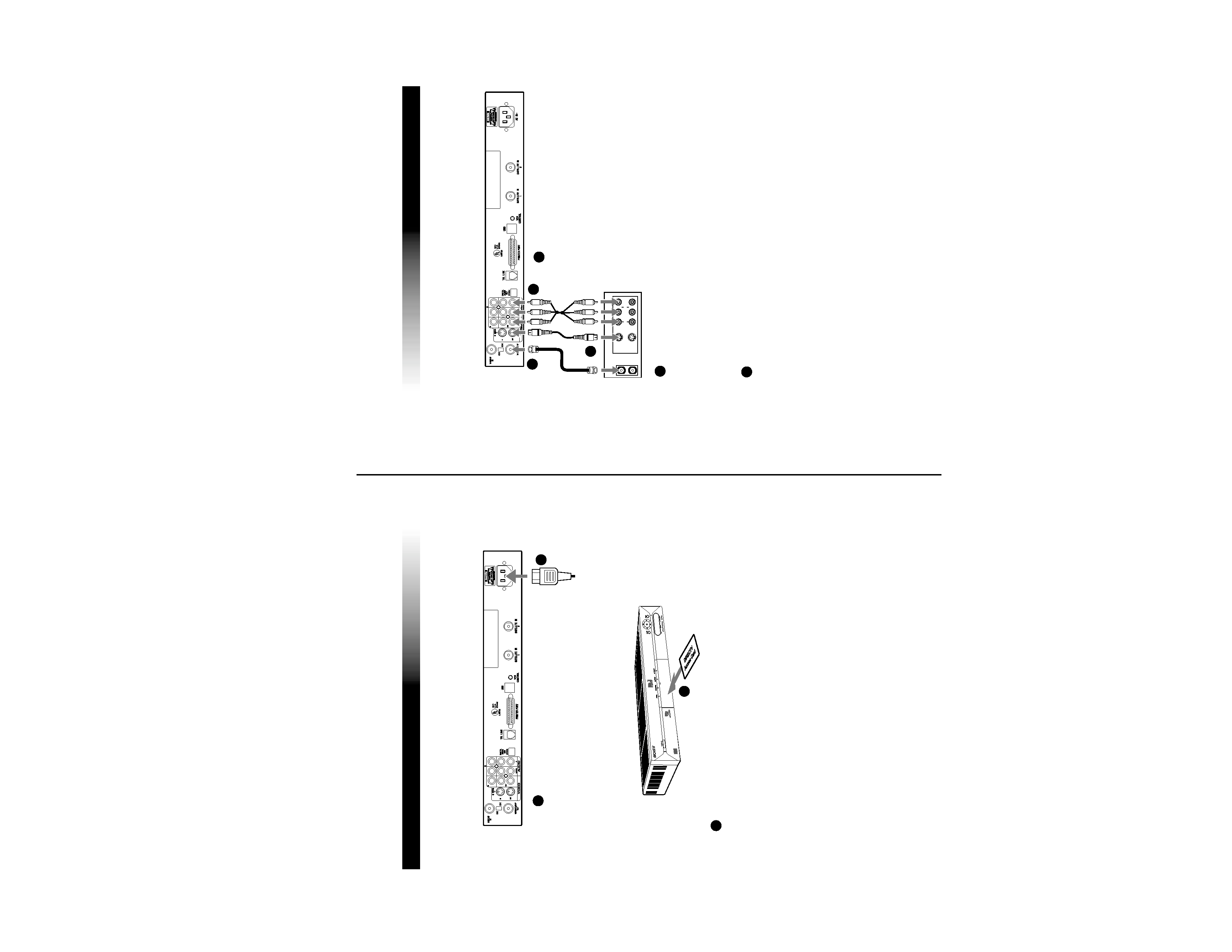
Advanced Connection: Connecting Your VCR
VIDEO
S VIDEO
AUDIO
LINE
IN
LINE
OUT
IN
OUT
VCR
Satellite Receiver
If your TV and VCR have A/V jacks
Connect the VIDEO OUT jacks of your Satellite
Receiver to the A/V input jacks of your VCR
using the supplied A/V cable. Then, connect
the A/V output jacks of your VCR to the A/V
input jacks of your TV using an A/V cable. (Be
sure to match the colors on the jacks with the
colored plugs on the A/V cable.) Some TVs
and VCRs do not have stereo audio, if yours
does not, just connect the white A/V cable to
the Left output jack.
1c
1b
1a
1a
1b
z Tip
To allow your Satellite Receiver to control the
recording functions of your VCR, see page 14.
If your TV and VCR do not have A/V jacks
Connect the VHF(SAT)/UHF OUT jack on the Satellite Receiver to the VHF/UHF input
jack on your VCR using coaxial cable.
Then, connect the VHF/UHF output jack on your VCR to the VHF/UHF input jack on
your TV using a second coaxial cable.
Set the CH3/CH4 switch to the channel that does not carry off-air broadcasts in your
area.
1c
If your TV and VCR have S-Video jacks
Use an S-Video cable instead of the yellow video connection. S-Video cable is
supplied.
Note
With this connection, your input source
is channel 3 or channel 4 depending on
how you set the CH3/CH4 switch on