9-965-896-02
HISTORY INFORMATION FOR THE FOLLOWING MANUAL:
SERVICE MANUAL
ORIGINAL MANUAL ISSUE DATE: 2/2001
ALL REVISIONS AND UPDATES TO THE ORIGINAL MANUAL ARE APPENDED TO THE END OF THE PDF FILE.
REVISION DATE
REVISION TYPE
SUBJECT
2/2001
No revisions or updates are applicable at this time.
3/2002
Supplement - 1
IC800 P/N changed on A Board
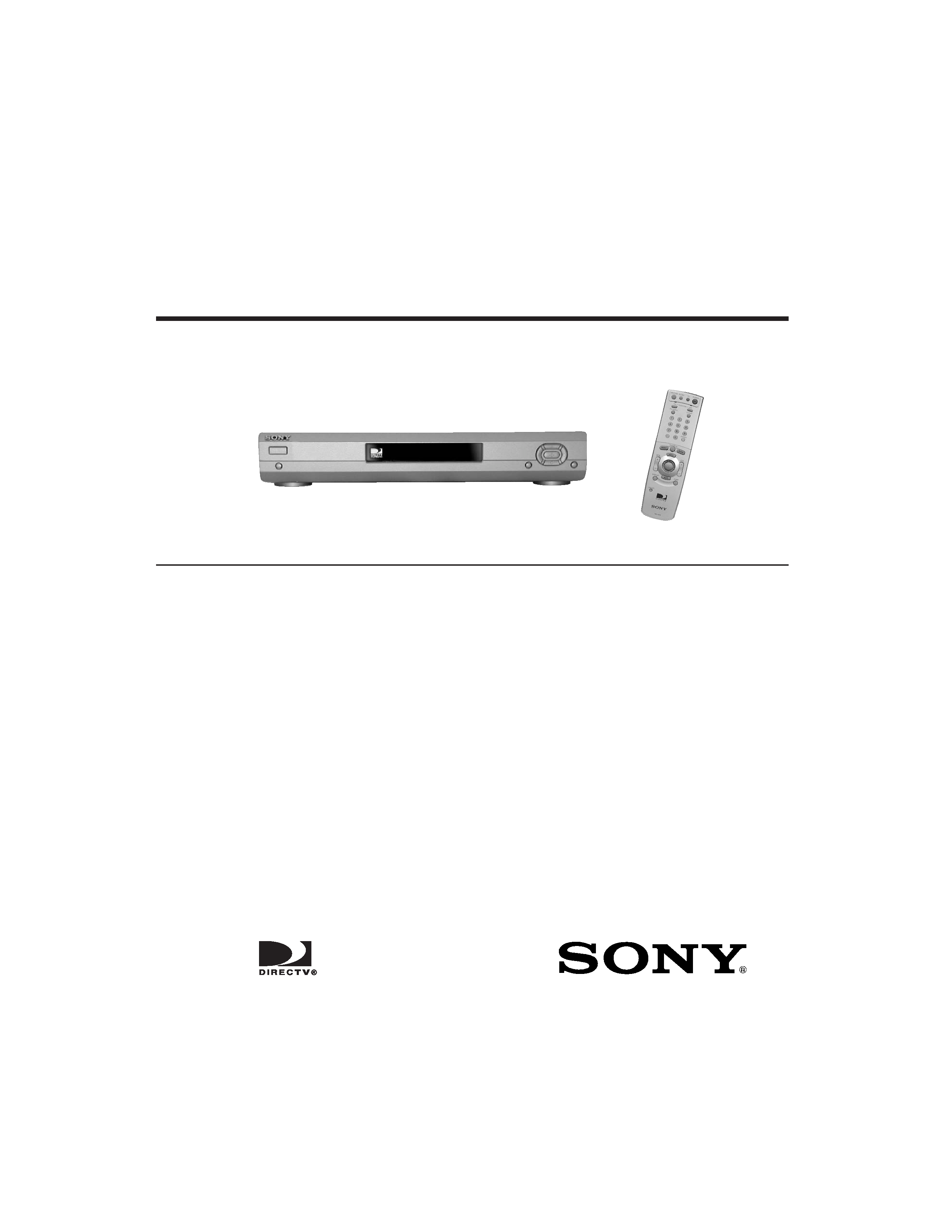
DIGITAL NETWORK RECEIVER
SAT-HD100 RM-Y808
U.S. Model
SERVICE MANUAL
DIGITAL SATELLITE RECEIVER
SAT-HD100
RM-Y808
SAT-HD100 RM-Y808
U.S. Model
Inputs and Outputs:
Video Out: S-Video 4-pin mini DIN (2)
Video Out: Composite Video RCA (2)
Video Out: Component Video
Y: RCA (1)
PB: RCA (1)
PR: RCA (1)
Video Out: VGA D-sub 15 pin (1)
Audio Line Out: Stereo L/R RCA (2 pairs)
Satellite In: F-Connector Female (1)
VHF/UHF In: F-Connector Female (1)
VHF/UHF (DTV) In: F-Connector Female (1)
VHF/UHF (SAT) Out: F-Connector Female (1)
Digital Audio Out: Optical (1)
Telephone: RJ-11 Female, 2 wire (1)
VCR Control Out: 3.5 mm Mini Jack Sockets (1)
RF Remote In: RCA (1)
Data Port: D-sub 9 pin (1)
General:
Power Requirements: 120 V AC, 60 Hz
Power Consumption: 50 W (max.)
Operating Temperature: 5°C to 35°C (41°F to 95°F)
Operating Humidity: 25% to 80%
Dimensions: Approx. 430 x 73 x 297 mm (w/h/d)
Approx. 17" x 3" x 11 3/4" (w/h/d)
(including projecting parts and controls)
Mass: Approx. 3.2 kg (7.0 lbs.)
Supplied Accessories:
Remote Control (1)
Size AA Batteries (2)
AC Power Cord (1)
Audio/Video Cable (1)
S-Video Cable (1)
Telephone Line Cord (1)
Access Card (1)
Y/PB/PR Cable (1)
Coaxial (RF) Cable (1)
VCR Controller (1)
RF Antenna (1)
Optional Sony-Brand Digital Satellite
Receiver Accessories:
Satellite Dish Antenna: SAN-18D3
SAN-24MD1
Local TV Antenna: ANJ-AA1
Installation Kit: ANJ-DS2
Amplifier: EAC-DA1
Diplexer: EAC-DD1
Voltage Switch: EAC-DV2
RF Universal Remote CommanderTM
Remote Control: RM-Y802
SPECIFICATIONS
896 Front.indd
01/29/01, 2:18 PM
1

-- 2 --
SAT-HD100

SAT-HD100
-- 3 --
TABLE OF CONTENTS
Warnings and Cautions...................................................................................................................... 4
Safety Check-out ............................................................................................................................... 5
1. Disassembly
1-1. Top Cover Removal ................................................................................................................... 6
1-2. Cable Dressing & Top Cover Re-assembly ............................................................................... 6
1-3. Front Panel Removal ................................................................................................................. 7
1-4. A, G, & TU Board Removal........................................................................................................ 8
2. Diagrams
2-1. Circuit Board Location ............................................................................................................... 9
2-2. Printed Wiring Boards and Schematic Diagrams....................................................................... 9
2-3. Diagrams
Block Diagram ......................................................................................................................... 10
A Board .................................................................................................................................... 13
FD Board ................................................................................................................................. 23
G Board ................................................................................................................................... 23
HA Board ................................................................................................................................. 23
HD Board ................................................................................................................................. 23
HP Board ................................................................................................................................. 23
TU Board ................................................................................................................................. 24
SC Board ................................................................................................................................. 25
2-4. Semiconductors ....................................................................................................................... 26
3. Exploded Views
3-1. Front ........................................................................................................................................ 27
3-2. Rear ......................................................................................................................................... 28
3-3. SAN-18D3................................................................................................................................ 29
3-4. SAN-24MD1............................................................................................................................. 29
4. Electrical Parts List .................................................................................................................................. 30
SECTION TITLE
PAGE
-- 4 --
SAT-HD100
WARNINGS AND CAUTIONS
! SAFETY-RELATED COMPONENT WARNING!!
Components identified by shading and ! mark on the schematic diagrams, exploded views, and in the parts list are critical for safe
operation. Replace these components with sony parts whose part numbers appear as shown in this manual or in supplements published
by sony. Circuit adjustments that are critical for safe operation are identified in this manual. Follow these procedures whenever critical
components are replaced or improper operation is suspected.
! ATTENTION AUX COMPOSANTS RELATIFS A LA SECURITE!!
Les composants identifies par une trame et par une marque ! sur les schemas de principe, les vues explosees et les listes de pieces sont
d'uneimportance critique pour la securite du fonctionnement. Ne les remplacer que par des composants sony dont le numero de piece est
indique dans le present manuel ou dans des supplements publies par sony. Les reglages de circuit dont l'importance est critique pour la
securite du fonctionnement sont identifies dans le present manuel. Suivre ces procedures lors de chaque remplacement de composants
critiques, ou lorsqu'un mauvais fontionnement suspecte.