SERVICE MANUAL
SAT-A55P RM-Y802
SAT-B55P RM-Y139
SAN-18D3
DIGITAL SATELLITE RECEIVER/SATELLITE ANTENNA
9-965-914-01
RM-Y802
SAN-18D3
SAT-A55P

-- 2 --
SAT-A55P/B55P
TABLE OF CONTENTS
Specifications........................................................................................................................................ 3
Warnings and Cautions......................................................................................................................... 4
Safety Check-out .................................................................................................................................. 5
1. Disassembly
1-1. Upper Case Removal .................................................................................................................... 6
1-2. A and SC2 Board Removal ........................................................................................................... 6
1-3. HB Board Removal........................................................................................................................ 6
2. Service Test .................................................................................................................................................... 6
3. Diagrams
3-1. Circuit Board Location ................................................................................................................... 7
3-2. Printed Wiring Boards and Schematic Diagrams .......................................................................... 7
3-3. Diagrams ....................................................................................................................................... 8
Block Diagram ............................................................................................................................... 8
A Board ....................................................................................................................................... 10
HB Board..................................................................................................................................... 16
SC2 Board................................................................................................................................... 17
3-4. Semiconductors........................................................................................................................... 18
4. Exploded Views
4-1. Chassis ........................................................................................................................................ 19
4-2. SAN-18D3.................................................................................................................................... 20
5. Electrical Parts List ..................................................................................................................................... 21
SECTION TITLE
PAGE

-- 3 --
SAT-A55P/B55P
FOR DIGITAL SATELLITE RECEIVER:
Input Jacks
UHF/VHF 75 ohm F-type
Satellite Antenna 75 ohm F-type
RF Remote Antenna (SAT-A55P Only)
AC Power (120V, 60Hz)
Output Jacks
S-VIDEO OUT, 4-pin mini DIN
VIDEO (RCA Jacks) (2)
AUDIO R/L (RCA Jacks) (2)
VHF (SAT)/UHF 75 ohms F-type
Low Speed Data, 9-pin D-sub Female
Telephone Line (RJ11)
VCR Control (1) VCR Controller
(or monoaural cable for Sony SmartFile VCRs)
Input Frequency
950 - 1450 Mhz / 950 - 2150 Mhz
Power Consumption
20 W maximum
Dimensions (w/h/d)
11 x 25/8 x 9 inches (280 x 66.5 x 228.5 mm)
Weight
SAT-A55P
SAT-B55P
Set: 6.0 lbs. (2.7 kg)
Set: 5.4 lbs (2.5 kg)
Unit: 3.6 lbs. (1.6 kg)
Unit: 3.4 lbs. (1.5 kg)
Supplied Accessories
Remote Commander RM-Y802 (SAT-A55P Only)
Remote Commander RM-Y139 (SAT-B55P Only)
Size AA Batteries (2)
Access Card (1)
Audio/Video Cable (1)
S-VIDEO Cable (1) (SAT-A55P Only)
Coaxial RF Cable (1)
RF Remote Antenna (1) (SAT-A55P Only)
VCR Controller (1)
Telephone Cable (1)
AC Power Cord (1)
SPECIFICATIONS
Design and specifications are subject to change without notice.
Optional Sony-brand DSS Accessories
Local TV Antenna ANJ-AA1
Installation Kit ANJ-DS2
Amplifier EAC-DA1
Diplexer EAC-DD1
Voltage Switch ECA-DV2
RF Universal Remote Commander
Remote Control RM-Y802
FOR SATELLITE ANTENNAS:
Input Frequency
12.2 - 12.7 GHz
Output Frequency
950 - 1450 MHz
Output Connector
F-Type Female
Power Consumption
3.0 W maximum
Supply Voltage
DC + 10.5 - 14.0 V for RHCP · DC + 15.5 - 21.0 V for LHCP
Dimensions (w/h/d)
185/8 x 31 x 185/16 inches (473 x 787 x 643 mm)
Weight
8 lbs., 6 oz. (3.8 kg)
Supplied Accessories
Weatherboot (2 pcs.)
Signal Seeker (1 pc.)
Snap-in Clip (dual type) (1 pc.)
Bolt for Ground Terminal (1 pc.)
Bolt for LNB Support Arm (2 pcs.)
Optional Accessories
Installation Kit ANJ-DS2
Amplifier EAC-DA1
Diplexer EAC-DD1
Voltage Switch ECA-DV2
Multi-Room A/V
Distribution System MDR-D1
Coaxial Cable 25 ft. SAK-C25
Coaxial Cable 75 ft. SAK-C75
Flat Cable DAK-F1

-- 4 --
SAT-A55P/B55P
WARNINGS AND CAUTIONS
! SAFETY-RELATED COMPONENT WARNING!!
Components identified by shading and ! mark on the schematic diagrams, exploded views, and in the parts list are critical for
safe operation. Replace these components with sony parts whose part numbers appear as shown in this manual or in supplements
published by sony. Circuit adjustments that are critical for safe operation are identified in this manual. Follow these procedures
whenever critical components are replaced or improper operation is suspected.
! ATTENTION AUX COMPOSANTS RELATIFS A LA SECURITE!!
Les composants identifies par une trame et par une marque ! sur les schemas de principe, les vues explosees et les listes de
pieces sont d'une importance critique pour la securite du fonctionnement. Ne les remplacer que par des composants sony dont
le numero de piece est indique dans le present manuel ou dans des supplements publies par sony. Les reglages de circuit dont
l'importance est critique pour la securite du fonctionnement sont identifies dans le present manuel. Suivre ces procedures lors de
chaque remplacement de composants critiques, ou lorsqu'un mauvais fonctionnement suspecte.
-- 5 --
SAT-A55P/B55P
SAFETY CHECK-OUT
After correcting the original service problem, perform the following
safety checks before releasing the set to the customer:
1. Check the area of your repair for unsoldered or poorly soldered
connections. Check the entire board surface for solder splashes and
bridges.
2. Check the interboard wiring to ensure that no wires are "pinched" or
touching high-wattage resistors.
3. Check that all control knobs, shields, covers, ground straps, and
mounting hardware have been replaced. Be absolutely certain that
you have replaced all the insulators.
4. Look for unauthorized replacement parts, particularly transistors,
that were installed during a previous repair. Point them out to the
customer and recommend their replacement.
5. Look for parts which, though functioning, show obvious signs of
deterioration. Point them out to the customer and recommend their
replacement.
6. Check the line cords for cracks and abrasion. Recommend the
replacement of any such line cord to the customer.
7. Check the B+ and HV to see if they are specified values. Make sure
your instruments are accurate; be suspicious of your HV meter if sets
always have low HV.
8. Check the antenna terminals, metal trim, "metallized" knobs, screws,
and all other exposed metal parts for AC leakage. Check leakage
as described below.
Leakage Test
The AC leakage from any exposed metal part to earth ground and from
all exposed metal parts to any exposed metal part having a return to
chassis, must not exceed 0.5 mA (500 microamperes). Leakage current
can be measured by any one of three methods.
1. A commercial leakage tester, such as the Simpson 229 or
RCA WT-540A. Follow the manufacturers' instructions to use these
instructions.
2. A battery-operated AC milliammeter. The Data Precision 245 digital
multimeter is suitable for this job.
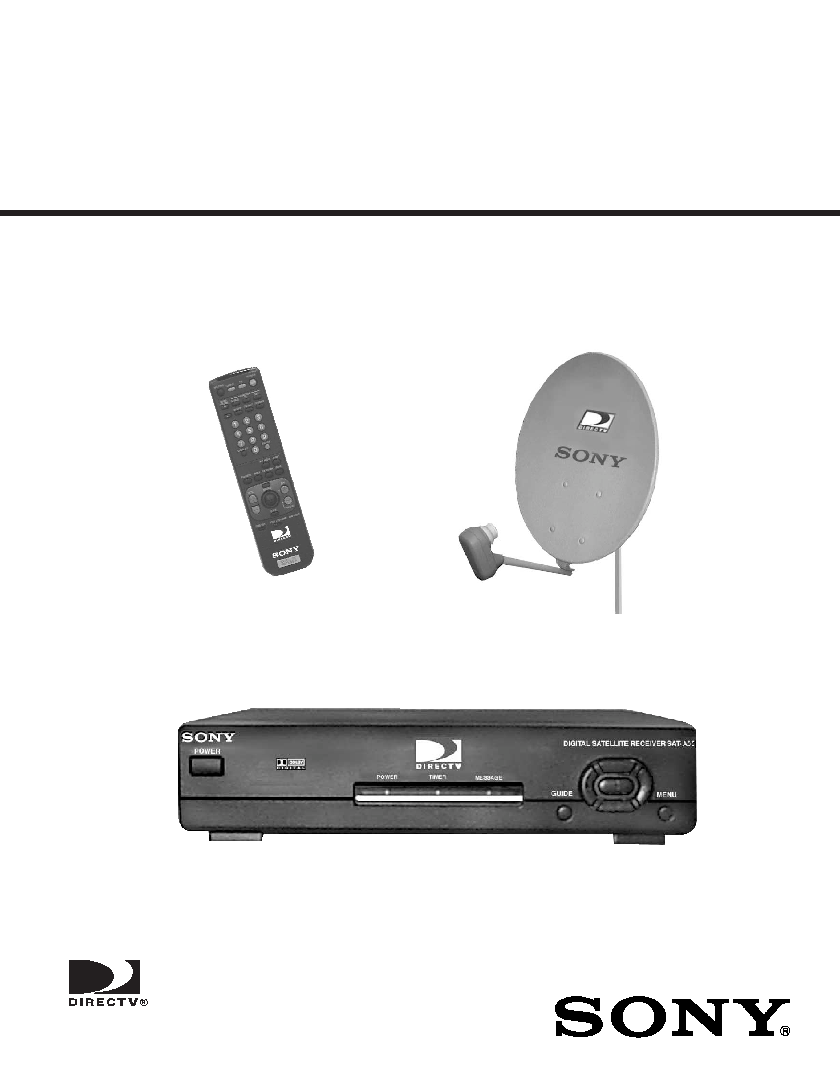
3. Measuring the voltage drop across a resistor by means of a VOM
or battery-operated AC voltmeter. The "limit" indication is 0.75 V,
so analog meters must have an accurate low voltage scale. The
Simpson's 250 and Sanwa SH-63TRD are examples of passive
VOMs that are suitable. Nearly all battery-operated digital multimeters
that have a 2 VAC range are suitable (see Figure A).
How to Find a Good Earth Ground
A cold-water pipe is a guaranteed earth ground; the cover-plate retaining
screw on most AC outlet boxes is also at earth ground. If the retaining
screw is to be used as your earth ground, verify that it is at ground
by measuring the resistance between it and a cold-water pipe with an
ohmmeter. The reading should be zero ohms.
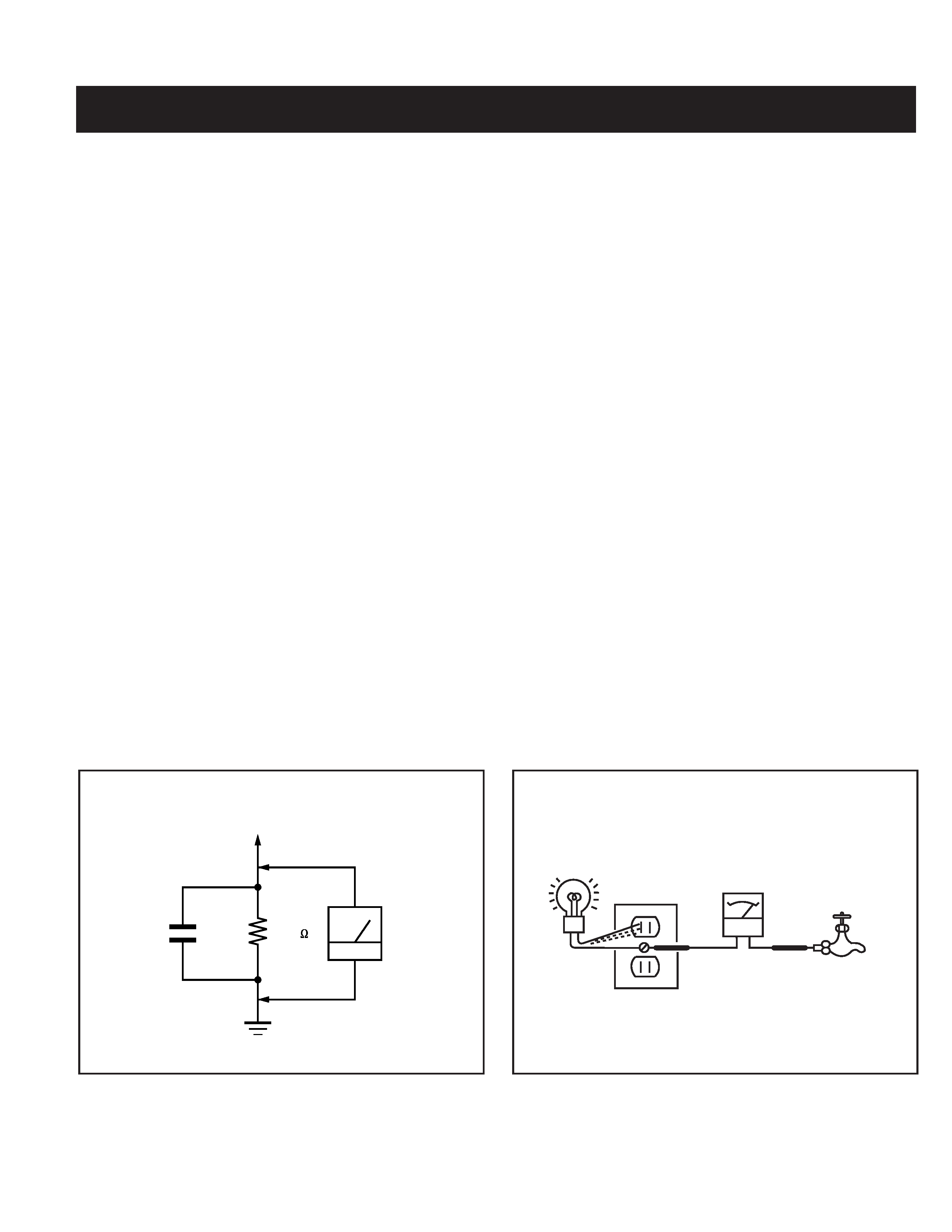
If a cold-water pipe is not accessible, connect a 60- to 100-watt trouble-
light (not a neon lamp) between the hot side of the receptacle and the
retaining screw. Try both slots, if necessary, to locate the hot side on the
line; the lamp should light at normal brilliance if the screw is at ground
potential (see Figure B).
Figure A. Using an AC voltmeter to check AC leakage.
Figure B. Checking for earth ground.
To Exposed Metal
Parts on Set
0.15 µF
Earth Ground
AC
Voltmeter
(0.75V)
1.5 k
Trouble Light
AC Outlet Box
Ohmmeter
Cold Water Pipe