SERVICE MANUAL
DIGITAL SATELLITE RECEIVER/SATELLITE ANTENNA
SAT-A55 RM-Y802
SAT-B55 RM-Y139
SAN-18D3
RM-Y802
SAT-A55
SAN-18D3
U.S. Model
1. SAT A55 B55 front.p65
1/14/00, 11:36 AM
1
-- 2 --
SAT-A55/B55
UHF/VHF 75 ohm F-type
Satellite Antenna 75 ohm F-type
RF Remote Antenna (SAT-A55 only)
AC Power (120V, 60 Hz)
S-VIDEO OUT
4-pin mini DIN
VIDEO (RCA jacks) (2)
AUDIO R/L (RCA jacks) (2)
VHF (SAT)/UHF 75 ohms F-Type
Low Speed Data, 9-pin D-Sub Female
Telephone Line (RJ11)
VCR control (1) VCR Controller (or monoaural cable for Sony SmartFile VCRs)
Optical output (1) (SAT-A55 only)
950 - 1450 Mhz / 950-2150 Mhz
120V AC, 60 Hz
20 W max.
11 x 25/8 x 9 inches
280 x 66.5 x 228.5 mm
SAT-A55
SAT-B55
Set: 6.0 lb (2.7 kg)
Set: 5.4 lb (2.5 kg)
Unit: 3.6 lb (1.6 kg)
Unit: 3.4 lb (1.5 kg)
Remote Commander RM-Y802 (SAT-A55)
Remote Commander RM-Y139 (SAT-B55)
Size AA Batteries (2)
Access Card (1)
Audio/Video Cable (1)
S-VIDEO Cable (1) (SAT-A55 only)
Coaxial RF Cable (1)
RF Remote Antenna (1) (SAT-A55 only)
VCR Controller (1)
Telephone Cable (1)
AC Power Cord (1)
SPECIFICATIONS
Local TV Antenna ANJ-AA1
Installation Kit ANJ-DS2
Amplifier EAC-DA1
Diplexer EAC-DD1
Voltage Switch ECA-DV2
RF Universal Remote Commander
Remote Control RM-Y802
Optional Sony-brand DSS Accessories
Design and specifications subject to change without notice.
Input Jacks
Output Jacks
Input Frequency
Power Requirements
Power Consumption
Dimensions (w/h/d)
Weight
Supplied Accessories
FOR DIGITAL SATELLITE RECEIVER:
-- 3 --
SAT-A55/B55
12.2 - 12.7 GHz
950 - 1450 MHz
F-Type Female
3.0 W max.
DC + 10.5 - 14.0 V for RHCP
DC + 15.5 - 21.0 V for LHCP
185/8 x 31 x 185/16 inches
473 x 787 x 643 mm
8 lbs 6 oz (3.8 kg)
FOR SATELLITE ANTENNAS:
SAFETY CHECK-OUT
1. Check the area of your repair for unsoldered or poorly-
soldered connections. Check the entire board surface for
solder splashes and bridges.
2. Check the interboard wiring to ensure that no wires are
"pinched" or contact high-wattage resistors.
3. Check that all control knobs, shields, covers, ground
straps, and mounting hardware have been replaced. Be
absolutely certain that you have replaced all the insulators.
4. Look for unauthorized replacement parts, particularly
transistors, that were installed during a previous repair.
Point them out to the customer and recommend their
replacement.
5. Look for parts which, though functioning, show obvious
signs of deterioration. Point them out to the customer and
recommend their replacement.
6. Check the line cords for cracks and abrasion. Recom-
mend the replacement of any such line cord to the
customer.
7. Check the B+ and HV to see if they are specified
values. Make sure your instruments are accurate; be
suspicious of your HV meter if sets always have low HV.
8. Check the antenna terminals, metal trim, "metallized"
knobs, screws, and all other exposed metal parts for AC
leakage using one of the methods listed.
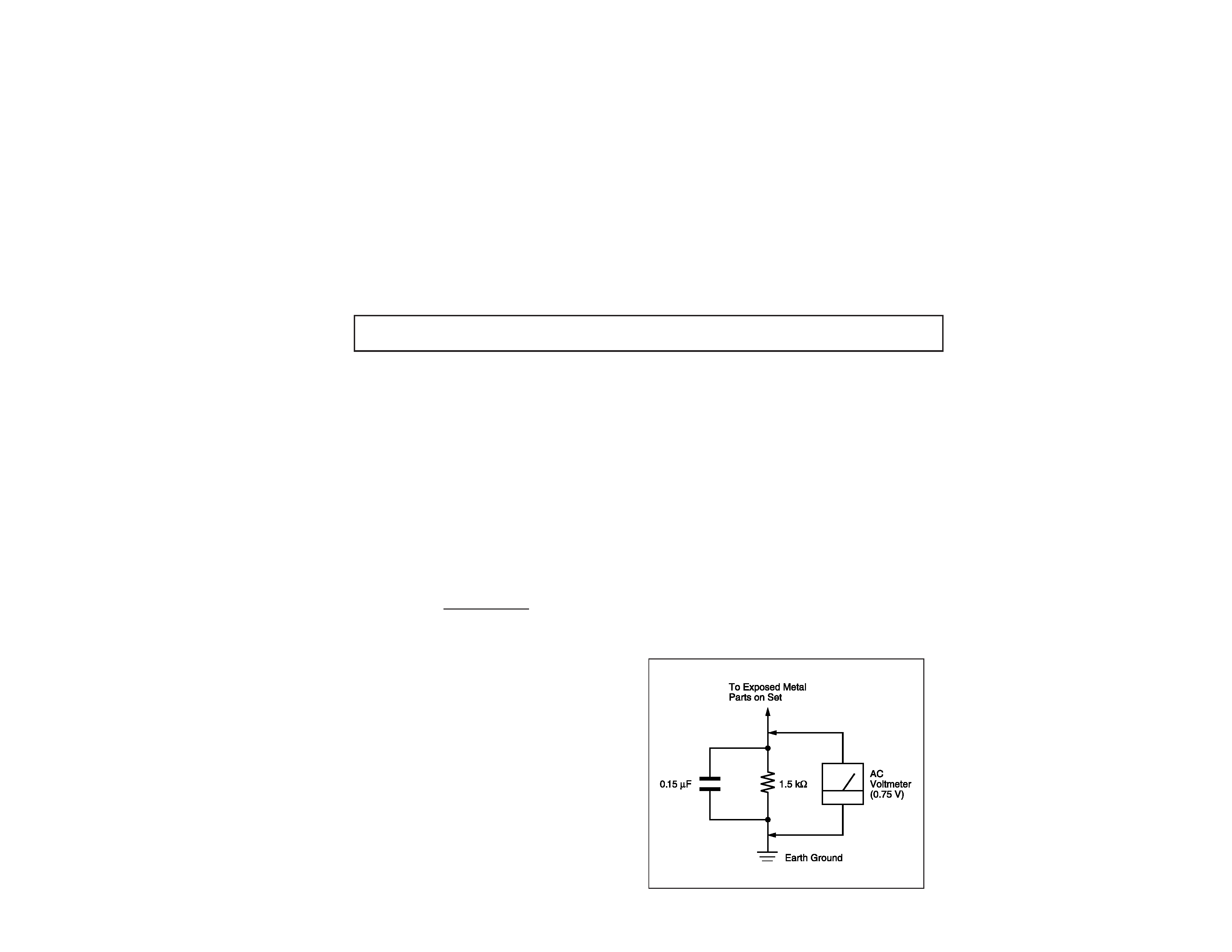
Figure 1. Using an AC voltmeter to check AC leakage.
LEAKAGE TEST
The AC leakage from any exposed metal part to earth
ground and from all exposed metal parts to any exposed
metal part having a return to chassis, must not exceed 0.5
mA (500 microamperes). Leakage current can be mea-
sured by any one of three methods.
1. A commercial leakage tester, such as the Simpson 229
or RCA WT-540A. Follow the manufacturers' instructions
to use these instruments.
2. A battery-operated AC milliammeter. The Data
Precision 245 digital multimeter is suitable for this job.
3. Measuring the voltage drop across a resistor by means
of a VOM or battery-operated AC voltmeter. The "limit"
indication is 0.75 V, so analog meters must have an
accurate low-voltage scale. The Simpson 250 and Sanwa
SH-63Trd are examples of passive VOMs that are
suitable. Nearly all battery operated digital multimeters
that have a 2 VAC range are suitable. (See Figure 1)
Input Frequency
Output Frequency
Output Connector
Power Consumption
Supply Voltage
Dimensions (w/h/d)
Weight
Supplied
Accessories
Optional
Accessories
Weatherboot 2pcs
Signal Seeker 1pc
Snap-in Clip (dual type) 1pc
Bolt for Ground Terminal 1pc
Bolt for LNB Support Arm 2pcs
Installation Kit ANJ-DS2
Amplifier EAC-DA1
Diplexer EAC-DD1
Voltage Switch ECA-DV2
Multi-Room A/V
Distribution System MDR-D1
Coaxial Cable 25' SAK-C25
Coaxial Cable 75' SAK-C75
Flat Cable SAK-F1
SAFETY CHECK-OUT
-- 4 --
SAT-A55/B55
1.
General
--------------------------------------------------------------------------- 5
2.
Disassembly
2-1.
Upper Case Removal ---------------------------------------------------- 12
2-2.
H Board Removal --------------------------------------------------------- 12
2-3.
A, SC Board Removal --------------------------------------------------- 12
3.
Service Test
---------------------------------------------------------------------- 12
4.
Diagrams
4-1.
Block Diagram -------------------------------------------------------------- 15
4-2.
Circuit Boards Location --------------------------------------------------- 18
4-3.
Schematic Diagrams and Printed Wiring Boards ----------------- 18
Schematic Diagrams of SC Board ------------------------------ 19
Schematic Diagrams of HB Board ------------------------------ 20
Schematic Diagram of A Board (1/4) -------------------------- 21
Schematic Diagram of A Board (2/4) -------------------------- 24
Schematic Diagram of A Board (3/4) -------------------------- 27
Schematic Diagram of A Board (4/4) -------------------------- 30
A Board PCB and Components Location --------------------- 33
4-4.
Semiconductors ------------------------------------------------------------ 37
5.
Exploded Views
5-1.
SAT-A55/B55 Chassis ---------------------------------------------------- 38
5-2.
SAN-18D3 -------------------------------------------------------------------- 39
6.
Electrical Parts List --------------------------------------------------------------- 40
Section
Title
Page
TABLE OF CONENTS
SAFETY-RELATED COMPONENT WARNING !!
Components identified by shading and the critical mark
on the schematic diagrams, exploded views, and in the
parts list are critical for safe operation. Replace these
with Sony parts whose part numbers appear as shown
in this manual or in supplements published by Sony.
Circuit adjustments that are critical for safe operation
are identified in this manual. Follow these procedures
whenever critical components are replaced or improper
operation is suspected.
!
--
5
--
SA
T-A55/B55
The operating instructions mentioned here are partial abstracts from the
Operating Manual. The page numbers referenced here reflect those of the
Operating Instruction Manual.
SECTION 1
GENERAL
8
The SATELLITE IN jack sends power to, and receives satellite signals
from, the Satellite Dish Antenna. The telephone line connection
periodically sends information about your receiver and Access Card to
your service provider.
Connections are shown using the SAT-A55 model. Any differences in connecting the SAT-B55
model are noted in the text.
ACCESS CARD
LOW SPEED DATA
VCR CONTROL
DIGITAL
OUT
(OPTICAL)
SATELLITE IN
RF REMOTE
R
L(MONO)
VIDEO OUT
AUDIO
VIDEO
S VIDEO
CH3
CH4
VHF/UHF IN
VHF(SAT)/UHF
OUT
TEL LINE
AC IN~
1
2
Digital Satellite Receiver
Connect the SATELLITE IN
jack to your Satellite Dish
Antenna using RG-6
coaxial cable.
RG-6 Coaxial Cable from
Satellite Dish Antenna
Telephone Cord
Connect the TEL LINE
jack to a telephone
line wall jack using
the supplied
telephone cord.
Note
· Your Satellite Dish Antenna
Installation Instructions
provides detailed instructions
on how to install RG-6 coaxial
cable from your Satellite Dish
Antenna.
CAUTION
Only connect your authorized
Satellite Dish Antenna to the
SATELLITE IN jack as described
in the Installation Instructions.
Connecting any other equipment
to this jack could result in damage
to the equipment and/or receiver.
1
1
2
2
Step 2: Connecting the Satellite Dish Antenna
and Telephone Line
9
P
L
US
TM
D
ig
ita
l
S
atell
ite
Receiver
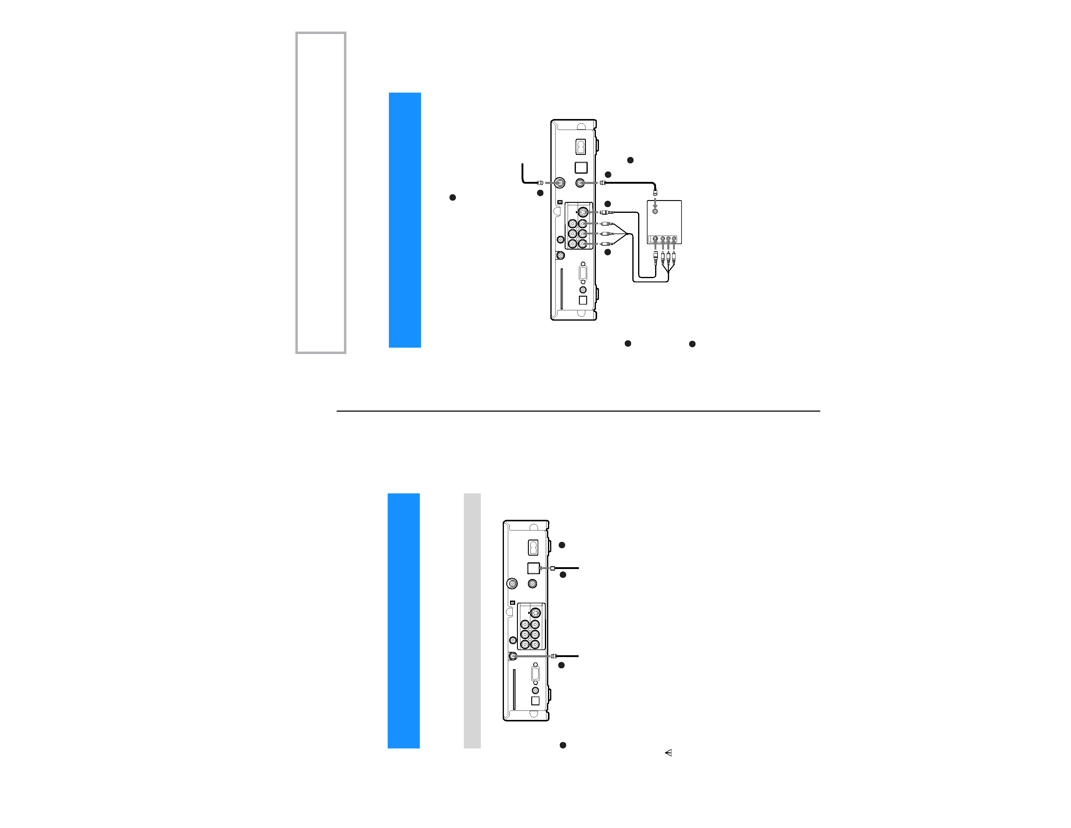
Connect your TV to the Digital Satellite Receiver as shown below. Refer
to your TV's instruction manual for more information.
ACCESS CARD
LOW SPEED DATA
VCR CONTROL
DIGITAL
OUT
(OPTICAL)
SATELLITE IN
RF REMOTE
R
L(MONO)
VIDEO OUT
AUDIO
VIDEO
S VIDEO
CH3
CH4
VHF/UHF IN
VHF(SAT)/UHF
OUT
TEL LINE
AC IN~
1
2
VHF/UHF
VIDEO
L(MONO)
R
S VIDEO
IN
-AUDIO-
If you have a local TV antenna or cable
company service
Connect it to the VHF/UHF IN jack on your Digital
Satellite Receiver using a coaxial cable or RF
adapter (not supplied).
You can view local stations using your TV controls.
Note
You must use the VHF(SAT)/UHF OUT jack to
connect to your TV or VCR when a local TV antenna
or cable company service is connected to the
VHF/UHF IN jack (see "2c" below and on page 10).
If your TV has A/V input
jacks
Connect the VIDEO OUT
jacksonyourDigital
Satellite Receiver to the
A/V input jacks on your TV
using the supplied A/V
cable. (Besuretomatch the
colors on the jacks with the
colored plugs on the A/V
cable.)
If your TV has an S-Video
input
Use an S-Video cable
instead of the yellow video
connection. S-Video cable is
supplied with the SAT-A55
model and is an optional
accessory with the SAT-B55
model.
If your TV has only one
audio input, connect it to
the L(MONO) jack on the
receiver.
If your TV does not have
A/V jacks
Connect the VHF(SAT)/UHF
OUT jack to the VHF/UHF
input jack on your TV using
coaxial cable.
Set the CH3/CH4 switch to the
channel that does not carry off-
airbroadcastsinyourarea.
Note
With this connection, your
input source is channel 3 or
channel 4 depending on how
you set the CH3/CH4 switch
on the receiver.
Digital Satellite Receiver
Coaxial
Cable
A/V Cable
VIDEO
(yellow)
OR
S-Video
S-Video
Cable
TV
Coaxial
Cable
1
1
2a
2a
2b
2b
2c
2c
Step 3: Connecting Your TV