
VIDEO PROJECTOR
VPL-VW100
REMOTE COMMANDER
RM-PJVW100
SERVICE MANUAL
1st Edition (Revised 1)
VPL-VW100
! WARNING
This manual is intended for qualified service personnel only.
To reduce the risk of electric shock, fire or injury, do not perform any servicing other than that
contained in the operating instructions unless you are qualified to do so. Refer all servicing to
qualified service personnel.
! WARNUNG
Die Anleitung ist nur für qualifiziertes Fachpersonal bestimmt.
Alle Wartungsarbeiten dürfen nur von qualifiziertem Fachpersonal ausgeführt werden. Um die
Gefahr eines elektrischen Schlages, Feuergefahr und Verletzungen zu vermeiden, sind bei
Wartungsarbeiten strikt die Angaben in der Anleitung zu befolgen. Andere als die angegeben
Wartungsarbeiten dürfen nur von Personen ausgeführt werden, die eine spezielle Befähigung
dazu besitzen.
! AVERTISSEMENT
Ce manual est destiné uniquement aux personnes compétentes en charge de l'entretien. Afin
de réduire les risques de décharge électrique, d'incendie ou de blessure n'effectuer que les
réparations indiquées dans le mode d'emploi à moins d'être qualifié pour en effectuer d'autres.
Pour toute réparation faire appel à une personne compétente uniquement.
CAUTION
RISK OF EXPLOSION IF BATTERY IS REPLACED BY INCORRECT TYPE.
DISPOSE OF USED BATTERIES ACCORDING TO THE RULE IN REGION.

1
VPL-VW100
Table of Contents
1.
Service Information
1-1.
Appearance Figure .......................................................... 1-1
1-2.
Board Locations .............................................................. 1-1
1-3.
Disassembly .................................................................... 1-2
1-3-1.
Top Cover Assembly ............................................. 1-5
1-3-2.
Lamp Cover ........................................................... 1-6
1-3-3.
Lamp ...................................................................... 1-6
1-3-4.
L Board .................................................................. 1-7
1-3-5.
Louver (F) Assembly ............................................ 1-7
1-3-6
Front Cover Assembly and HB Board .................. 1-8
1-3-7.
Hood Section ......................................................... 1-9
1-3-8.
UA Board and UB Board ...................................... 1-9
1-3-9.
HA Block Assembly ............................................ 1-10
1-3-10.
Hood Assembly and NR Board ........................... 1-11
1-3-11.
GB Board ............................................................. 1-12
1-3-12.
Lamp Power Supply ............................................ 1-12
1-3-13.
Optics Unit Assembly-1 ...................................... 1-13
1-3-14.
Optics Unit Assembly-2 ...................................... 1-14
1-3-15.
Igniter .................................................................. 1-15
1-3-16.
TA Board ............................................................. 1-15
1-3-17.
D.C. Motor SFF21C/C-NP (Right)
and D.C. Motor SFF21C/C-NP (Left) ................. 1-16
1-3-18.
GA Board ............................................................ 1-17
1-3-19.
D.C. Fan (Sirocco) .............................................. 1-17
1-3-20.
Q Board ............................................................... 1-18
1-3-21.
F Board ................................................................ 1-19
1-3-22.
Bottom Cover Assembly ..................................... 1-19
1-3-23.
Extension Boards and Extension Cables ............. 1-20
1-3-24.
Extension Boards Connection ............................. 1-20
1-4.
Network ........................................................................ 1-22
1-4-1.
Overview ............................................................. 1-22
1-4-2.
Service Preparation ............................................. 1-22
1-4-3.
Firmware Update Function .................................. 1-24
1-4-4.
Event Trace Function .......................................... 1-31
1-4-5.
Network Reset ..................................................... 1-34
1-5.
Unleaded Solder ............................................................ 1-34
1-6.
Service Know-How ...................................................... 1-35
1-6-1.
When the Optical Unit ASSY is Replaced .......... 1-35
1-6-2.
When the Board is Replaced ............................... 1-35
1-6-3.
IRIS Adjustment .................................................. 1-35
1-7.
Upgrading the Software ................................................ 1-35
1-8.
Memory ......................................................................... 1-37
2.
Electrical Adjustments
2-1.
Preparations .................................................................... 2-1
2-1-1.
Required Equipment .............................................. 2-1
2-1-2.
Factory Mode Setting ............................................ 2-1
2-2.
Adjustment Item Initialize Data ...................................... 2-2
2-3.
White Balance Adjustment on Servicing ........................ 2-9
2-3-1.
Component ............................................................ 2-9
2-3-2.
Computer ............................................................. 2-10
3.
Semiconductors
4.
Spare Parts
4-1.
Notes on Repair Parts ..................................................... 4-1
4-2.
Exploded Views .............................................................. 4-2
4-3.
Electrical Parts List ....................................................... 4-14
5.
Block Diagrams
C (1/2) ........................................................................................ 5-1
C (2/2) ........................................................................................ 5-2
GA, GB (1/2), F ......................................................................... 5-3
GB (2/2) ..................................................................................... 5-4
C, F, GA, HA, HB, L, NF, NR, Q, QB, TA, TL, V .................. 5-5
Q (1/6) ....................................................................................... 5-6
Q (2/6) ....................................................................................... 5-7
Q (3/6) ....................................................................................... 5-8
Q (4/6) ....................................................................................... 5-9
Q (5/6) ..................................................................................... 5-10
Q (6/6) ..................................................................................... 5-11

2
VPL-VW100
6.
Diagrams
6-1.
Frame Schematic Diagrams ............................................ 6-2
6-2.
Schematic Diagrams and Printed Wiring Boards ........... 6-3
Schematic Diagrams
Q (1/24) ........................................................................... 6-3
Q (2/24) ........................................................................... 6-4
Q (3/24) ........................................................................... 6-5
Q (4/24) ........................................................................... 6-6
Q (5/24) ........................................................................... 6-7
Q (6/24) ........................................................................... 6-8
Q (7/24) ........................................................................... 6-9
Q (8/24) ......................................................................... 6-10
Q (9/24) ......................................................................... 6-11
Q (10/24) ....................................................................... 6-12
Q (11/24) ....................................................................... 6-13
Q (12/24) ....................................................................... 6-14
Q (13/24) ....................................................................... 6-15
Q (14/24) ....................................................................... 6-16
Q (15/24) ....................................................................... 6-17
Q (16/24) ....................................................................... 6-18
Q (17/24) ....................................................................... 6-19
Q (18/24) ....................................................................... 6-20
Q (19/24) ....................................................................... 6-21
Q (20/24) ....................................................................... 6-22
Q (21/24) ....................................................................... 6-23
Q (22/24) ....................................................................... 6-24
Q (23/24) ....................................................................... 6-25
Q (24/24) ....................................................................... 6-26
C (1/9) ........................................................................... 6-32
C (2/9) ........................................................................... 6-33
C (3/9) ........................................................................... 6-34
C (4/9) ........................................................................... 6-35
C (5/9) ........................................................................... 6-36
C (6/9) ........................................................................... 6-37
C (7/9) ........................................................................... 6-38
C (8/9) ........................................................................... 6-39
C (9/9) ........................................................................... 6-40
F .................................................................................... 6-43
GA (1/2) ........................................................................ 6-46
GA (2/2) ........................................................................ 6-47
GB (1/5) ........................................................................ 6-50
GB (2/5) ........................................................................ 6-51
GB (3/5) ........................................................................ 6-52
GB (4/5) ........................................................................ 6-53
GB (5/5) ........................................................................ 6-54
HA ................................................................................. 6-56
HB ................................................................................. 6-57
L .................................................................................... 6-58
NF ................................................................................. 6-58
NR ................................................................................. 6-58
TA ................................................................................. 6-59
TL ................................................................................. 6-59
UA ................................................................................. 6-60
UB ................................................................................. 6-60
V ................................................................................... 6-60
Printed Wiring Boards
Q ................................................................................... 6-28
C .................................................................................... 6-30
F .................................................................................... 6-42
GA ................................................................................. 6-44
GB ................................................................................. 6-48
HA ................................................................................. 6-56
HB ................................................................................. 6-57
L .................................................................................... 6-58
NF ................................................................................. 6-58
NR ................................................................................. 6-58
TA ................................................................................. 6-59
TL ................................................................................. 6-59
UA ................................................................................. 6-60
UB ................................................................................. 6-60
V ................................................................................... 6-60
1-1
VPL-VW100
Section 1
Service Information
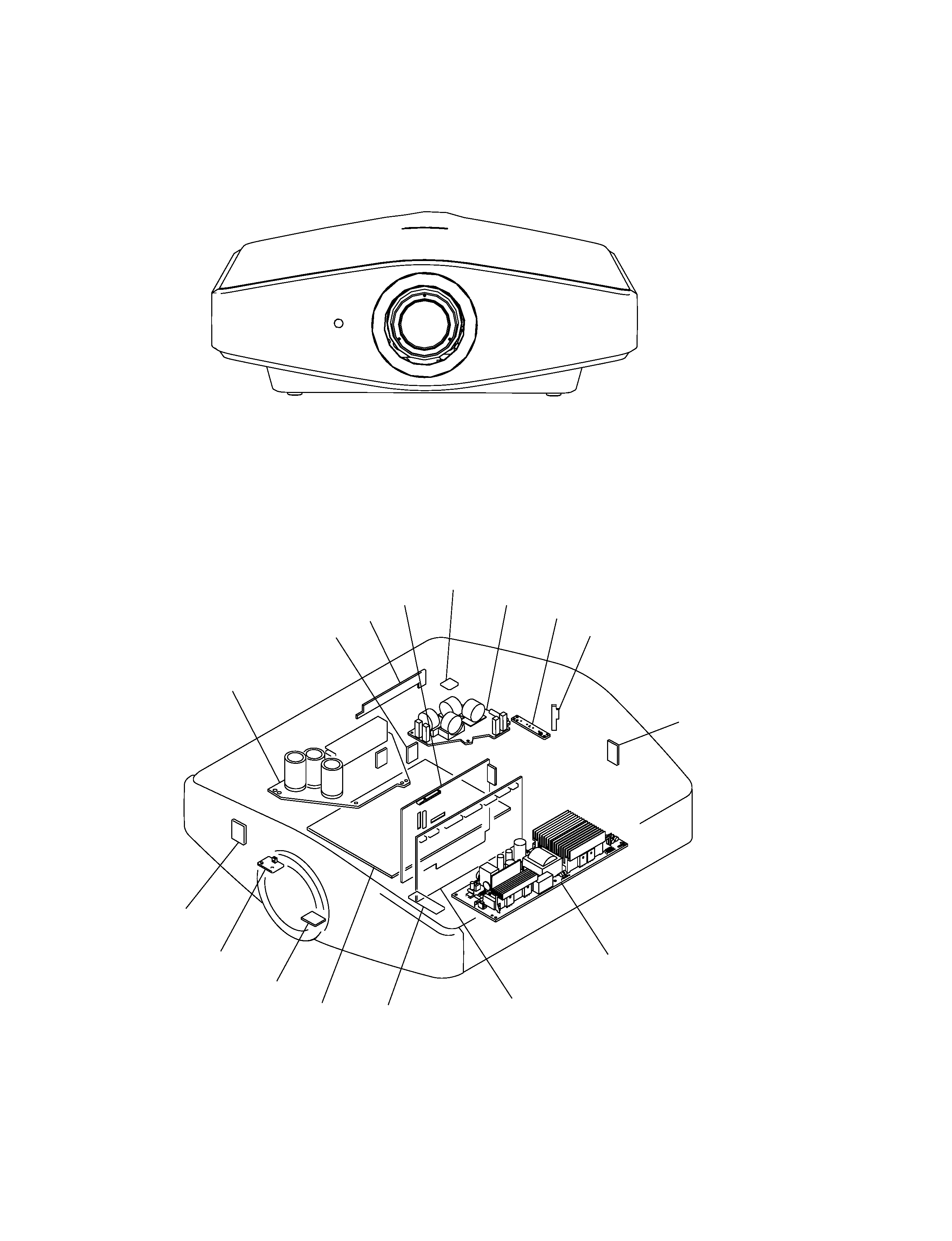
1-1. Appearance Figure
Lamp power supply
NR
UA
GB
L
F
UB
HA
C
GA
HB
Q
NF
TA
V
TL
1-2. Board Locations