RM-NX7000
US Model
SERVICE MANUAL
INTEGRATED REMOTE COMMANDER
Sony Corporation
Personal Audio Company
Published by Sony Engineering Corporation
9-877-700-01
2004C02-1
© 2004.04
SPECIFICATIONS
Ver 1.0 2004. 04
OS
LINUX
CPU
i.MX1 Application Processor 200MHz
Memory
32 MB (RAM)
User memory range: approx. 15 MB
Interface
Interface connector
USB. "Memory Stick" slot
Display
TFT color LCD with backlight
320 x 240 pixels (65,536 colors)
Dimensions
Approx. 101 x 165 x 50 mm (w x h x d)
(4 x 61/2 x 2 inches)
Mass
320 g (111/2 ounce) (including batteries)
Operating temperature recommended
5 ºC to 35 ºC (41 ºF to 95 ºF)
Operating distance*
Approx. 10 meters (32.8 feet) (front distance)
Learnable signals**
Capacity par signal: up to 300 bits
Signal frequency range: up to 500 kHz***
Signal interval: up to 1 second***
Power requirements
Supplied AC power adaptor: DC 4.5 V
(dedicated connector)
Built-in, rechargeable and non-removable
Ni-MH batteries (2)
Battery Life
Approx. 1 day (varies depending on
frequency of use)
Supplied accessories
Battery charging stand (1)
AC power adaptor (1)
USB cable (1)
Stylus (1)
Installation CD-ROM (1)
Operating Instructions (1, this manual)
Brochure (1)
Warranty Card (1)
Other printed materials (1 set)
*
The operating distance varies depending
on components of different
manufacturers.
** Some signals cannot be learned by the
Remote Commander, even though the
signals comply with these specifications.
***Depending on the component, some
signals may not be learned by the
Commander.
Design and specifications are subject to
change without notice.

2
RM-NX7000
TABLE OF CONTENTS
Specifications ............................................................................ 1
1.
GENERAL ................................................................... 3
2.
DISASSEMBLY
2-1.
Disassembly Frow ........................................................... 5
2-2.
Case (Lower) Nickel Hydrogen Battery .......................... 5
2-3.
Case (Upper) Block Assy ................................................ 6
2-4.
Switch Block Assy ........................................................... 6
2-5.
Main Board ...................................................................... 7
3.
TEST MODE ............................................................... 8
4.
DIAGRAM
4-1.
Block Diagram Main Section (1/2) .......................... 10
4-2.
Block Diagram Main Section (2/2) .......................... 11
4-3.
Shematic Diagram Main Section (1/6) ..................... 12
4-4.
Shematic Diagram Main Section (2/6) ..................... 13
4-5.
Shematic Diagram Main Section (3/6) ..................... 14
4-6.
Shematic Diagram Main Section (4/6) ..................... 15
4-7.
Shematic Diagram Main Section (5/6) ..................... 16
4-8.
Shematic Diagram Main Section (6/6) ..................... 17
4-9.
Plinted Wiring Board Main Section (Side A) ........... 18
4-10. Plinted Wiring Board Main Section (Side B) ........... 19
4-11. Shematic Diagram LED Section .............................. 20
4-12. Plinted Wiring Board LED Section ......................... 20
5.
EXPLODED VIEWS ................................................. 21
6.
ELECTRICAL PARTS LIST .................................. 22
Flexible Circuit Board Repairing
· Keep the temperature of the soldering iron around 270
°C
during repairing.
· Do not touch the soldering iron on the same conductor of the
circuit board (within 3 times).
· Be careful not to apply force on the conductor when soldering
or unsoldering.
Notes on chip component replacement
· Never reuse a disconnected chip component.
· Notice that the minus side of a tantalum capacitor may be
damaged by heat.
· Memory Stick and
are trademarks of Sony Corporation.
· Memory Stick Duo,
and "Memory Stick PRO"
are trademarks of Sony Corporation.
·"TouchEngine" is a trademark of Sony Corporation.
· Microsoft and Windows are registered trademarks of Microsoft
Corporation in the United States and/or other countries.
· All other names of systems and products are trademarks or
registered trademarks of their respective owners. TM and ® marks
are omitted in this manual.
· Microsoft® Windows® XP Professional and Microsoft® Windows®
XP Home Edition are mentioned as Windows XP in this manual.
· Microsoft® Windows® 2000 Professional is mentioned as Windows
2000 in this manual.
· Microsoft® Windows® Millennium Edition is mentioned as
Windows Me in this manual.
· Microsoft® Windows® 98 Second Edition is mentioned as Windows
98 SE in this manual.
Unleaded solder
Boards requiring use of unleaded solder are printed with the lead-
free mark (LF) indicating the solder contains no lead.
(Caution: Some printed circuit boards may not come printed with
the lead free mark due to their particular size.)
: LEAD FREE MARK
Unleaded solder has the following characteristics.
· Unleaded solder melts at a temperature about 40
°C higher than
ordinary solder.
Ordinary soldering irons can be used but the iron tip has to be
applied to the solder joint for a slightly longer time.
Soldering irons using a temperature regulator should be set to
about 350
°C.
Caution: The printed pattern (copper foil) may peel away if
the heated tip is applied for too long, so be careful!
· Strong viscosity
Unleaded solder is more viscous (sticky, less prone to flow)
than ordinary solder so use caution not to let solder bridges
occur such as on IC pins, etc.
· Usable with ordinary solder
It is best to use only unleaded solder but unleaded solder may
also be added to ordinary solder.
Note on chip component replacement
· Never reuse a disconnected chip component.
· Notice that the minus side of a tantalum capacitor may be
damaged by heat.
· IC1 (microcomputer) and IC7 (flash RAM) on Main board
cannot be replaced individually.
Replace it with Main board assembly for service.
3
RM-NX7000
SECTION 1
GENERAL
This section is extracted
from instruction manual.
1
2
3
Touch panel display
Shows operation keys and various pieces of
information.
Direct Access buttons
Directly skips to the page that is programmed
for the button.
NEXT/BACK buttons
Change the page shown on the touch panel dis-
play. Press the NEXT button to display the next
page, or press the BACK button to display the
previous one.
4 OK button and Cursor Control buttons
Used to operate the menu display of a component
being controlled by the Remote Commander.
5 MENU button
Shows the menu display of a component being
controlled by the Remote Commander.
6 EXIT button
Exits the menu of a component being control-
led by the Remote Commander.
7 Memory Stick slot
Used to insert a "Memory Stick."
8 HOME button
Returns to the first page of the Home display.
9 COMMANDER OFF button
Turns off the indication of the touch panel
display.
If this button is pressed while a macro is
executed, the macro procedure stops.
0 CH +/ buttons
Select a channel.
qa RECALL button
The function of this button varies depend-
ing on the component being controlled by
the Remote Commander.
qs VOL +/ buttons
Adjust the volume.
qd MUTING button
Mutes the audio of a component being con-
trolled by the Remote Commander. Press
the button once again to resume at the pre-
vious volume.
BACK
NEXT
HOME
OK
VOL
CH
MENU
EXIT
MUTING
RECALL
COMMANDER
OFF
INTEGRATED
REMOTE COMMANDER
1
2
3
4
5
6
7
8
9
0
qa
qs
qd
· Location and function of controls
· Front panel
4
RM-NX7000
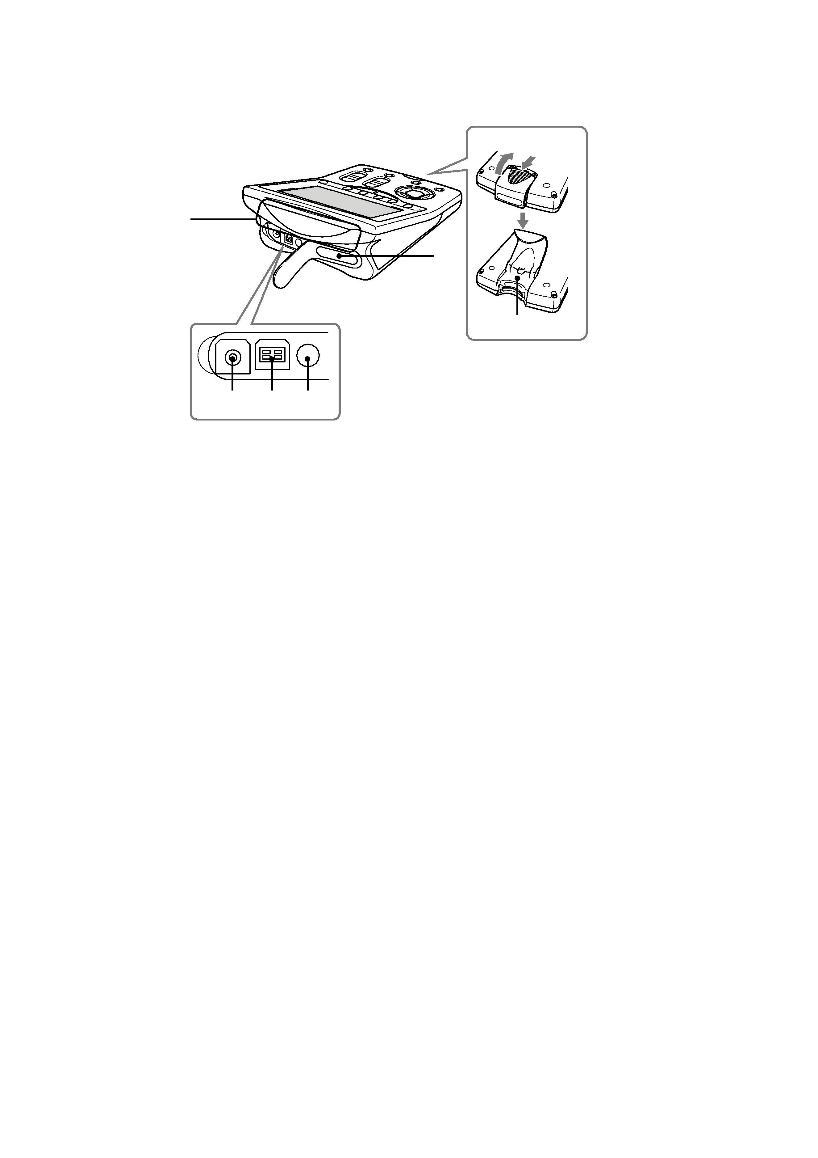
qf DC IN jack
Used to connect the supplied AC power adaptor.
O USB connector
Used to connect the USB cable for computer
connection.
P Stylus holder
Used to store the supplied Stylus.
Q Infrared detector/Infrared emitter
This is the area for receiving the component's
remote control signal or transmitting the Re-
mote Commander's signal.
R Infrared emitter
S RESET button
Used to restart the Remote Commander.
Rear
qf
O
P
Q
R
S
· Upper and rear panel
5
RM-NX7000
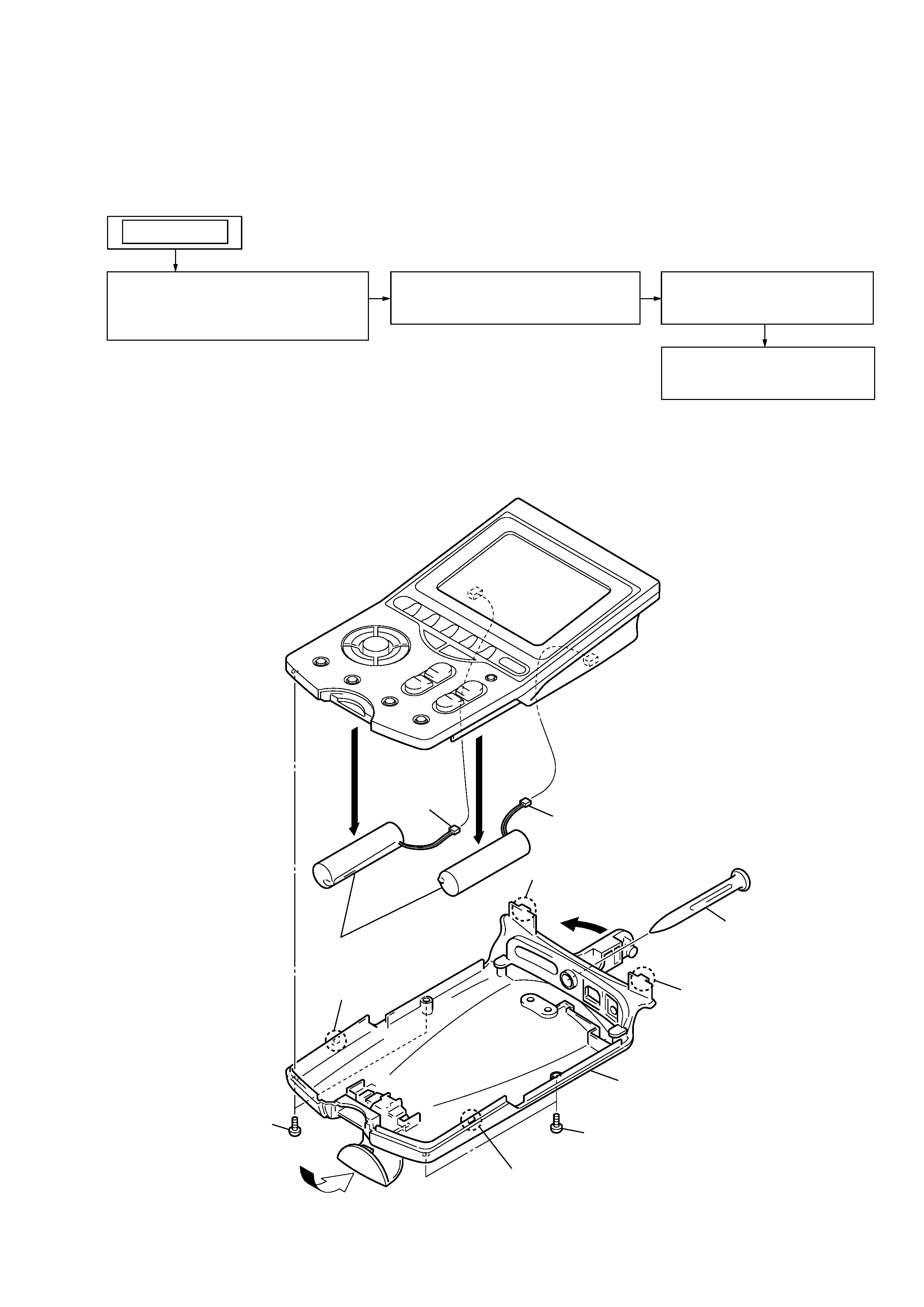
SECTION 2
DISASSEMBLY
· This set can be disassembled in the order shown below.
2-2. CASE (LOWER), NICKEL HYDROGEN BATTERY
1
5
2
stylus pen
qa
CN601
qs
CN602
qd
nickel hydrogen battery
3
two screws (+P 2.6X8)
4
two screws
(+P 2X6)
6
claw
7
claw
q;
case (lower)
9
claw
8
claw
2-2
3-2. CASE (LOWER),
NICKEL HYDROGEN BATTERY
(Page 5)
SET
2-3
CASE (UPPER) BLOCK ASSY
(Page 6)
2-4
SWITCH BLOCK ASSY
(Page 6)
2-5
MAIN BOARD
(Page 7)
2-1. DISASSEMBLY FLOW
Note: Follow the disassembly procedure in the numerical order given.