THEATRE STAND SYSTEM
US Model
Canadian Model
SPECIFICATIONS
RHT-G2000
Ver. 1.0 2005.08
9-879-844-01
2005H02-1
© 2005.08
Sony Corporation
Audio Group
Published by Sony Engineering Corporation
SERVICE MANUAL
AUDIO POWER SPECIFICATIONS
POWER OUTPUT AND TOTAL HARMONIC DISTORTION:
With 4 ohm loads, both channels driven, from 200 20,000 Hz; rated
40 watts per channel minimum RMS power, with no more than 0.7 %
total harmonic distortion from 250 milli watts to rated output.
Amplifier section
Surround mode (reference)
power output
Front: 100 W + 100 W 4 ohms
Center*: 100 W 4 ohms
Surround*: 100 W + 100 W 4 ohms
Subwoofer*: 200 W 2 ohms
* Depending on the sound field settings and the source, there may
be no sound output.
Inputs (Analog)
TV, SAT, DVD,
VIDEO 1, VIDEO 2
Sensitivity: 610 mV
Impedance: 25 kilohms
Inputs (Digital)
TV, SAT, DVD, VIDEO 1,
VIDEO 2 (Coaxial)
Impedance: 75 ohms
Tuner section
System
PLL quartz-locked digital synthesizer
system
FM tuner section
Tuning range
87.5 108.0 MHz (100 kHz step)
Antenna
FM wire antenna
Antenna terminals
75 ohms, unbalanced
Intermediate frequency
10.7 MHz
AM tuner section
Tuning range
530 1,710 kHz
(with the interval set at 10 kHz)
531 1,710 kHz
(with the interval set at 9 kHz)
This system incorporates Dolby* Digital and Pro Logic Surround and
the DTS** Digital Surround System.
* Manufactured under license from Dolby Laboratories.
"Dolby", "Pro Logic" and the double-D symbol are trademarks of Dolby Laboratories.
** "DTS" and "DTS Digital Surround" are registered trademarks of Digital Theater Systems,
Inc.
Antenna
AM loop antenna
Intermediate frequency
450 kHz
Video section
Inputs/Outputs
Video: 1 Vp-p 75 ohms
COMPONENT:
Y: 1 Vp-p 75 ohms
PB/CB, PR/CR: 0.7 Vp-p 75 ohms
Accepts 480i/480p/720p/1080i
Speakers
Front
Speaker system
Bass reflex, magnetically shielded
Speaker unit
65 mm (2 5/8 inches) cone type
Center
Speaker system
Bass reflex, magnetically shielded
Speaker unit
65 mm (2 5/8 inches) cone type
Surround
Speaker system
Bass reflex, magnetically shielded
Speaker unit
65 mm (2 5/8 inches) cone type
× 2
Subwoofer
Speaker system
Bass reflex, magnetically shielded
Speaker unit
160 mm (6 3/8 inches) cone type
× 2
Continued on next page
2
RHT-G2000
SAFETY-RELATED COMPONENT WARNING!!
COMPONENTS IDENTIFIED BY MARK 0 OR DOTTED LINE
WITH MARK 0 ON THE SCHEMATIC DIAGRAMS AND IN
THE PARTS LIST ARE CRITICAL TO SAFE OPERATION.
REPLACE THESE COMPONENTS WITH SONY PARTS WHOSE
PART NUMBERS APPEAR AS SHOWN IN THIS MANUAL OR
IN SUPPLEMENTS PUBLISHED BY SONY.
UNLEADED SOLDER
Boards requiring use of unleaded solder are printed with the lead-
free mark (LF) indicating the solder contains no lead.
(Caution: Some printed circuit boards may not come printed with
the lead free mark due to their particular size.)
: LEAD FREE MARK
Unleaded solder has the following characteristics.
· Unleaded solder melts at a temperature about 40
°C higher than
ordinary solder.
Ordinary soldering irons can be used but the iron tip has to be
applied to the solder joint for a slightly longer time.
Soldering irons using a temperature regulator should be set to
about 350
°C.
Caution: The printed pattern (copper foil) may peel away if
the heated tip is applied for too long, so be careful!
· Strong viscosity
Unleaded solder is more viscous (sticky, less prone to flow)
than ordinary solder so use caution not to let solder bridges
occur such as on IC pins, etc.
· Usable with ordinary solder
It is best to use only unleaded solder but unleaded solder may
also be added to ordinary solder.
General
Power requirements
120 V AC, 60 Hz
Power consumption
On: 120 W
Standby: 0.3 W
(at the Standby Mode)
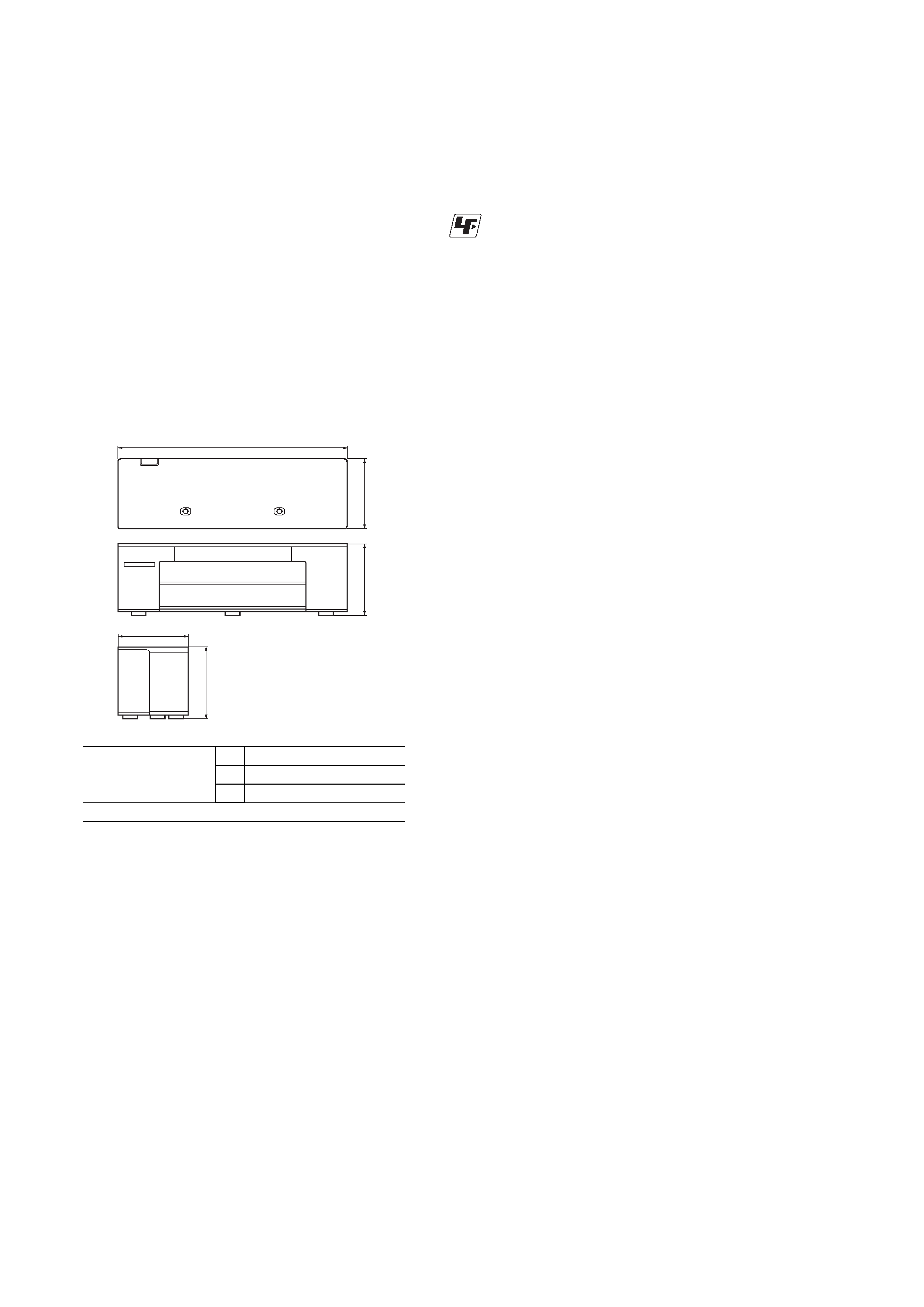
Dimensions (approx.)
1,570
× 500 × 570 mm
(61 7/8
× 19 3/4 × 22 1/2 inches) (w/h/d)
incl. projecting parts
Mass (approx.)
79 kg (174 lb 3 oz)
Supplied accessories
AM loop antenna (1)
FM wire antenna (1)
Input Box (4)
System cable (4)
Optical cable (1)
Video cord (blue/green/red) (1)
Video cord (yellow) (1)
Remote commander (remote) (1)
Size AA (R6) batteries (2)
Operating Instructions (1)
Quick Setup Guide (card) (1)
Rated impedance (external SP)
4 ~ 16 ohms
Dimensions:
mm (inch)
A
1,570 (61 7/8)
B
500 (19 3/4)
C
500 (19 3/4)
Weight: kg (oz)
79 (174 lb 3 oz)
A
C
C
B
B
Design and specifications are subject to change without notice.
Notes on chip component replacement
· Never reuse a disconnected chip component.
· Notice that the minus side of a tantalum capacitor may be
damaged by heat.
ATTENTION AU COMPOSANT AYANT RAPPORT
À LA SÉCURITÉ!
LES COMPOSANTS IDENTIFIÉS PAR UNE MARQUE 0 SUR LES
DIAGRAMMES SCHÉMATIQUES ET LA LISTE DES PIÈCES
SONT CRITIQUES POUR LA SÉCURITÉ DE FONCTIONNEMENT.
NE REMPLACER CES COMPOSANTS QUE PAR DES PIÈCES
SONY DONT LES NUMÉROS SONT DONNÉS DANS CE MANUEL
OU DANS LES SUPPLÉMENTS PUBLIÉS PAR SONY.
3
RHT-G2000
TABLE OF CONTENTS
1.
GENERAL ................................................................... 4
2.
DISASSEMBLY
2-1.
AMP Assy ........................................................................
6
3.
TEST MODE ............................................................... 7
4.
DIAGRAMS ................................................................. 8
4-1.
Block Diagram Video Section ..................................
9
DSP Section ............................................................... 10
Audio Section ............................................................ 11
Power Section ............................................................ 12
4-2.
Printed Wiring Board MAIN Board (Side A) ........... 13
4-3.
Printed Wiring Board MAIN Board (Side B) ........... 14
4-4.
Schematic Diagram MAIN Board (1/8) ................... 15
4-5.
Schematic Diagram MAIN Board (2/8) ................... 16
4-6.
Schematic Diagram MAIN Board (3/8) ................... 17
4-7.
Schematic Diagram MAIN Board (4/8) ................... 18
4-8.
Schematic Diagram MAIN Board (5/8) ................... 19
4-9.
Schematic Diagram MAIN Board (6/8) ................... 20
4-10. Schematic Diagram MAIN Board (7/8) ................... 21
4-11. Schematic Diagram MAIN Board (8/8) ................... 22
4-12. Printed Wiring Board IO Board (Side A) ................. 23
4-13. Printed Wiring Board IO Board (Side B) ................. 24
4-14. Schematic Diagram IO Board .................................. 25
4-15. Printed Wiring Board Panel Section (Side A) .......... 26
4-16. Printed Wiring Board Panel Section (Side B) .......... 27
4-17. Schematic Diagram Panel Section ........................... 28
4-18. Printed Wiring Board In/Out/Power Section ............ 29
4-19. Schematic Diagram In/Out/Power Section ............... 30
4-20. Printed Wiring Board Input Box Section ................. 31
4-21. Schematic Diagram Input Box Section .................... 32
5.
EXPLODED VIEWS
5-1.
Grille Frame Section ....................................................... 42
5-2.
Panel Section ................................................................... 43
5-3.
Speaker Section ............................................................... 44
5-4.
Amp Section-1 ................................................................. 45
5-5.
Amp Section-2 ................................................................. 46
5-6.
Amp Section-3 ................................................................. 47
5-7.
Input Box Section ............................................................ 48
6.
ELECTRICAL PARTS LIST .................................. 49
After correcting the original service problem, perform the following
safety checks before releasing the set to the customer:
Check the antenna terminals, metal trim, "metallized" knobs, screws,
and all other exposed metal parts for AC leakage. Check leakage as
described below.
LEAKAGE
The AC leakage from any exposed metal part to earth ground and
from all exposed metal parts to any exposed metal part having a
return to chassis, must not exceed 0.5 mA (500 microamperes).
Leakage current can be measured by any one of three methods.
1. A commercial leakage tester, such as the Simpson 229 or RCA
WT-540A. Follow the manufacturers' instructions to use these
instruments.
2. A battery-operated AC milliammeter. The Data Precision 245
digital multimeter is suitable for this job.
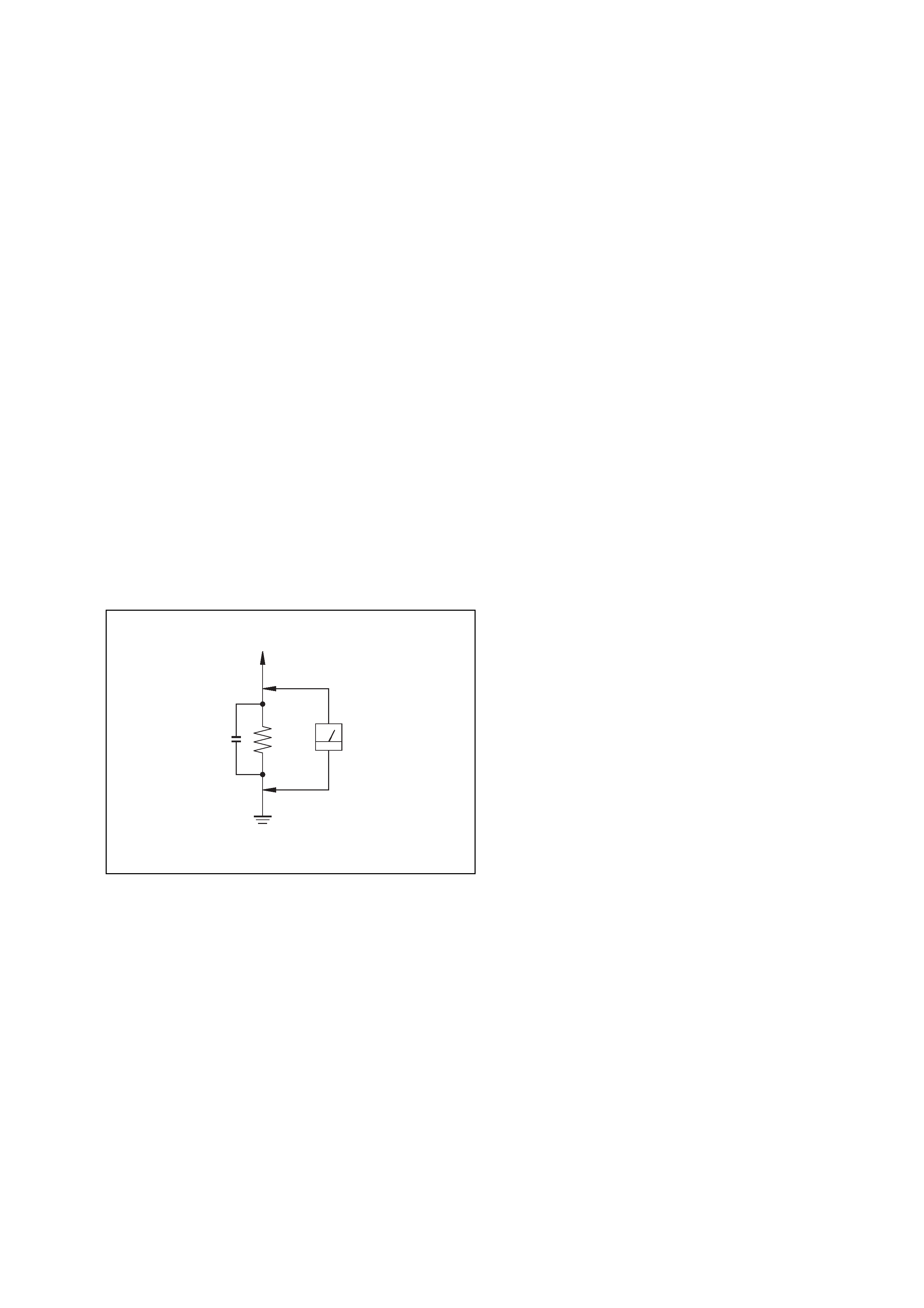
3. Measuring the voltage drop across a resistor by means of a
VOM or battery-operated AC voltmeter. The "limit" indication
is 0.75 V, so analog meters must have an accurate low-voltage
scale. The Simpson 250 and Sanwa SH-63Trd are examples
of a passive VOM that is suitable. Nearly all battery operated
digital multimeters that have a 2V AC range are suitable. (See
Fig. A)
SAFETY CHECK-OUT
To Exposed Metal
Parts on Set
0.15
µF
1.5 k
AC
Voltmeter
(0.75 V)
Earth Ground
Fig. A. Using an AC voltmeter to check AC leakage.
4
RHT-G2000
SECTION 1
GENERAL
This section is extracted from
instruction manual.
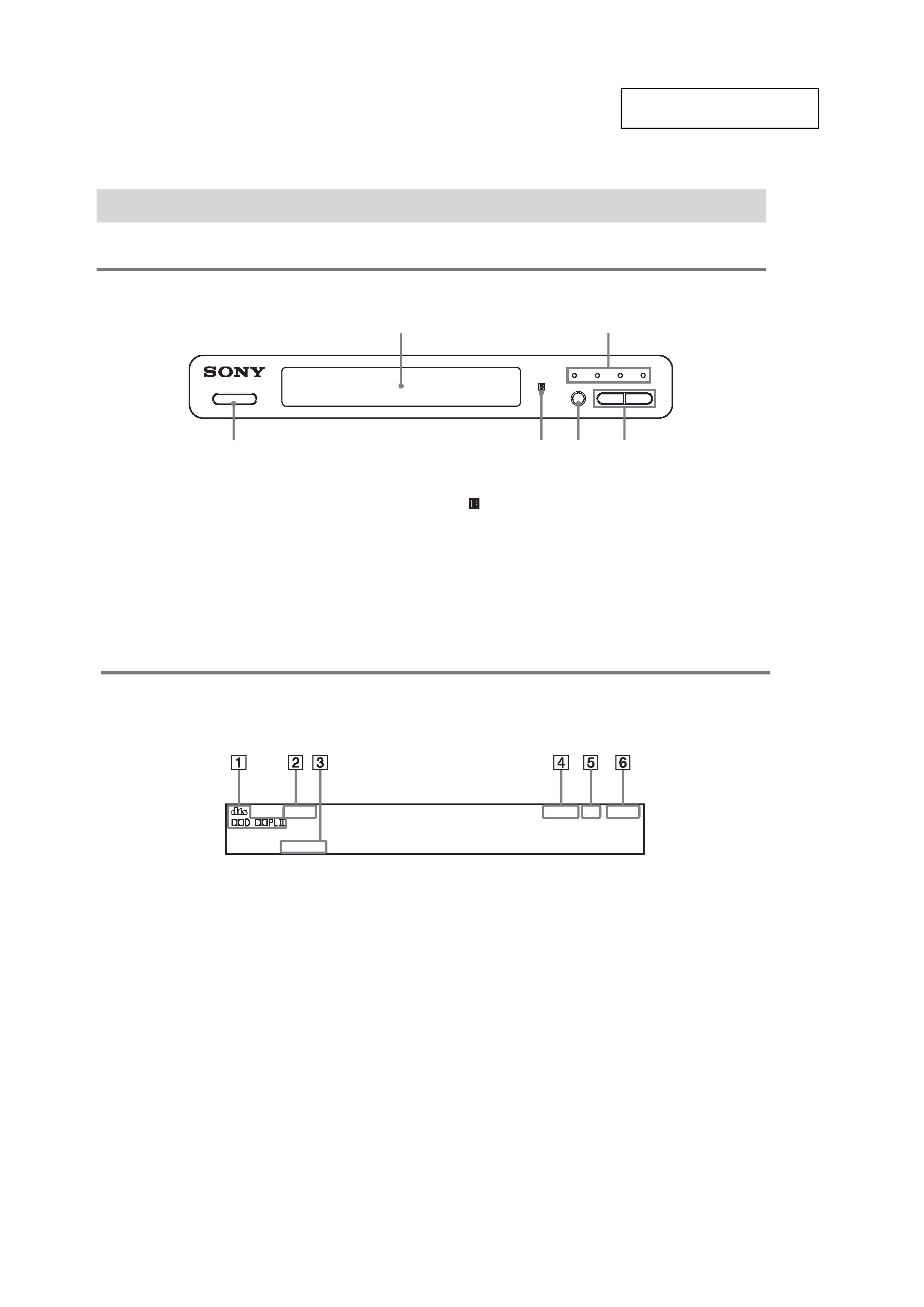
LOCATING THE CONTROLS
For more information, refer to the pages indicated in parentheses.
Front panel
A Front panel display
B Sound field indicator
C VOLUME +/
D INPUT SELECTOR
E
(remote sensor)
F "/1 (on/standby)
Index to Parts and Controls
?/1
1
6
4
3
5
2
Front panel display
About the indications in the front panel display
A Current surround format
B Lights up in SLEEP mode.
C Lights up when A/V SYNC is functioning.
D Lights up when a radio station is tuned.
E Lights up when a stereo broadcast is tuned.
F Lights up when listening to the radio in monaural
effect.
TUNED ST
MONO
SLEEP
A/V SYNC
5
RHT-G2000
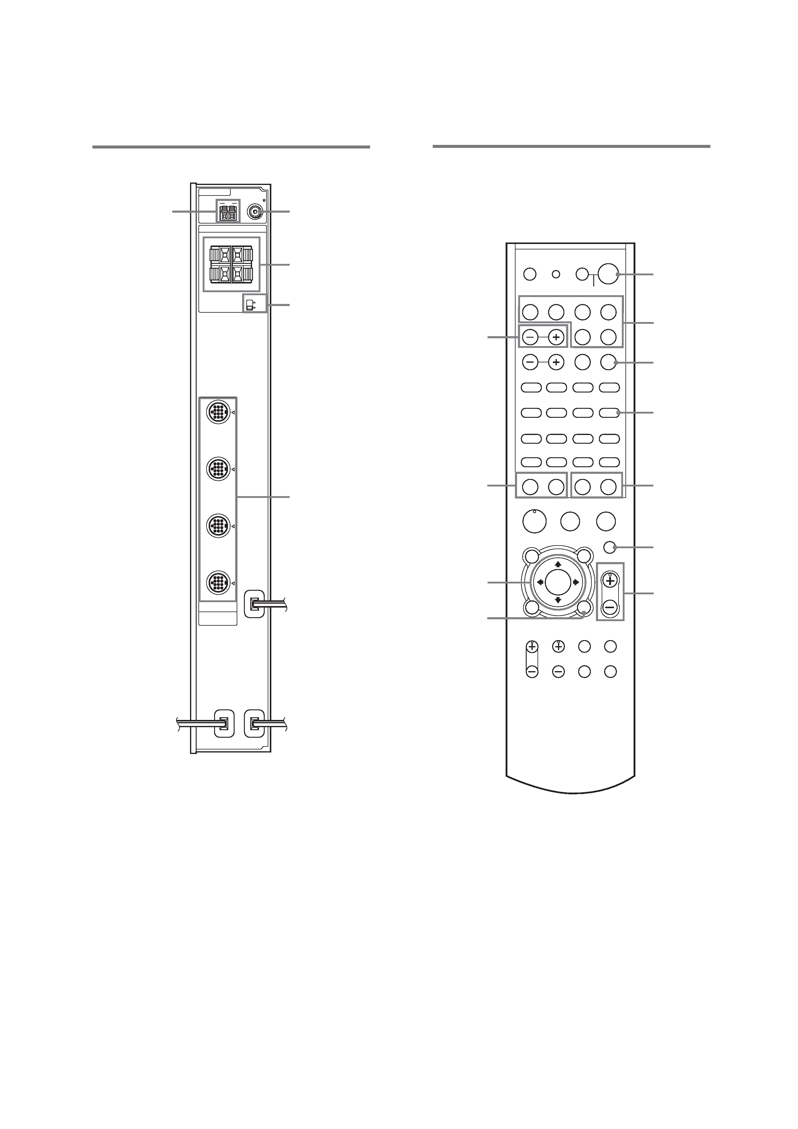
Rear panel
A COAXIAL FM 75
jack
B SPEAKER TERMINALS For Real 5.1 mode
C 5.1CH/FRONT mode switch
D AUDIO VIDEO INPUT jacks
E AM terminal
ANTENNA
AM
COAXIAL
FM
L
R
5.1CH
FRONT
MODE
L
SURROUND
SAT
+
-
+
-
R
75
SPEAKERS
AUDIO VIDEO
INPUT
DVD
VIDEO 2
VIDEO 1
2
3
4
5
1
Remote control
Here describes the buttons for amplifier operation only. See
page 12 for the buttons for operation of the connected
components.
A "/1 (on/standby)
B Input buttons
C AMP MENU
D TUNER MENU
E PRESET +/
F MUTING
G VOLUME +/
The VOLUME + button has a tactile dot.*
H DISPLAY (19)
I C/X/x/c/ENTER
J TUNING +/
K SOUND FIELD +/
*Use the tactile dot as a reference when operating the system.
H
X
M
m.
>
-
VIDEO1
VIDEO2
TV
DVD
RM SETUP
SYSTEM STANDBY
TV ?/1
AV ?/1
SOUND FIELD
TUNER/BAND
CH/DISC SKIP
SLEEP
AMP
MENU
SAT
TOP MENU/
GUIDE
AV MENU
MUTING
VOLUME
RETURN/EXIT
TV VOL
TV CH
TV/
VIDEO
ANT
JUMP
WIDE
DISPLAY
- TUNING +
- PRESET +
13
46
7
2
5
89
12/SET
>10/11
0/10
ENTER
CLEAR
FM MODE
AUDIO
ANGLE
TUNER MENU
SUBTITLE
x
?/1
P
O
1
2
5
6
0
3
4
7
9
8
qa