SERVICE MANUAL
DVD RECORDER
SPECIFICATIONS
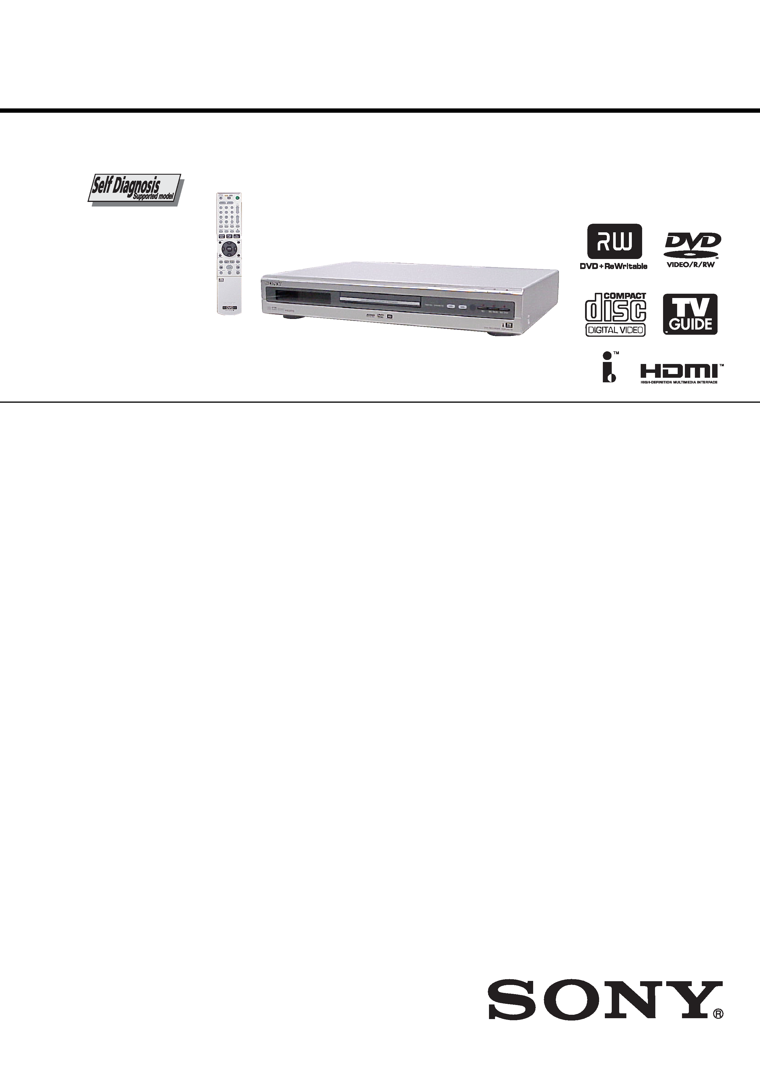
RDR-HX715
RMT-D218A
US Model
Canadian Model
System
Laser: Semiconductor laser
Channel coverage:
NTSC
VHF: 2 to 13/UHF: 14 to 69/CATV: A-8 to
A-1, A to W, W+1 to W+84
Video reception: Frequency synthesizer system
Audio reception: Split carrier system
Antenna: 75-ohm antenna terminal for VHF/
UHF
Timer: Clock: Quartz locked/Timer indication:
12-hour cycle (digital)/Power back-up
duration: 1 hour
Video recording format: MPEG Video
Audio recording format/applicable bit
rate: Dolby Digital 2 ch/256 kbps
Inputs and outputs
LINE OUT 1/2
(AUDIO): Phono jack/2 Vrms/10 kilohms
(VIDEO): Phono jack/1.0 Vp-p
(S VIDEO): 4-pin mini DIN/Y: 1.0 Vp-p,
C: 0.286 Vp-p
LINE IN 1/2/3
(AUDIO): Phono jack/2 Vrms/more than
22 kilohms
(VIDEO): Phono jack/1.0 Vp-p
(S VIDEO): 4-pin mini DIN/Y: 1.0 Vp-p,
C: 0.286 Vp-p
DV IN: 4-pin/i.LINK S100
DIGITAL OUT (OPTICAL): Optical output jack/
18 dBm (wave length: 660 nm)
DIGITAL OUT (COAXIAL): Phono jack/
0.5 Vp-p/75 ohms
COMPONENT VIDEO OUT (Y, PB, PR):
Phono jack/Y: 1.0 Vp-p/PB, PR:
interlace*=0.648 Vp-p, progressive or
interlace**=0.7 Vp-p
COMPONENT VIDEO IN (Y, PB, PR):
Phono jack/Y: 1.0 Vp-p/PB, PR:
interlace*=0.648 Vp-p, progressive or
interlace**=0.7 Vp-p
*
"Y/Pb/Pr Out Black Level" is "On"
** "Y/Pb/Pr Out Black Level" is "Off"
SET TOP BOX CONTROL:
Mini jack
HDMI OUT:
Type A (19-pin)
General
Power requirements: 120 V AC, 60 Hz
Power consumption: 57 W
Dimensions (approx.): 430
× 75 × 328 mm
(17
× 3 × 13 in.) (width/height/depth) incl.
projecting parts
Hard disk drive capacity: 160 GB
Mass (approx.): 5.3 kg (11.68 lb)
Operating temperature:
5
°C to 35°C (41°F to 95°F)
Operating humidity: 25% to 80%
Supplied accessories:
Audio/video cord (1)
Power cord (1)
Antenna cable (1)
Set top box controller (1)
Remote commander (remote) (1)
Size AA (R6) batteries (2)
Specifications and design are subject to change
without notice.
-- 2 --
SAFETY-RELATED COMPONENT WARNING!!
COMPONENTS IDENTIFIED BY MARK 0 OR DOTTED LINE WITH
MARK 0 ON THE SCHEMATIC DIAGRAMS AND IN THE PARTS
LIST ARE CRITICAL TO SAFE OPERATION. REPLACE THESE
COMPONENTS WITH SONY PARTS WHOSE PART NUMBERS
APPEAR AS SHOWN IN THIS MANUAL OR IN SUPPLEMENTS
PUBLISHED BY SONY.
1.
Check the area of your repair for unsoldered or poorly-soldered
connections. Check the entire board surface for solder splashes
and bridges.
2.
Check the interboard wiring to ensure that no wires are
"pinched" or contact high-wattage resistors.
3.
Look for unauthorized replacement parts, particularly
transistors, that were installed during a previous repair. Point
them out to the customer and recommend their replacement.
4.
Look for parts which, through functioning, show obvious signs
of deterioration. Point them out to the customer and
recommend their replacement.
5.
Check the B+ voltage to see it is at the values specified.
6.
Flexible Circuit Board Repairing
· Keep the temperature of the soldering iron around 270°C
during repairing.
· Do not touch the soldering iron on the same conductor of the
circuit board (within 3 times).
· Be careful not to apply force on the conductor when soldering
or unsoldering.
SAFETY CHECK-OUT
After correcting the original service problem, perform the following
safety checks before releasing the set to the customer.
CAUTION
Use of controls or adjustments or performance of procedures
other than those specified herein may result in hazardous radiation
exposure.
WARNING!!
WHEN SERVICING, DO NOT APPROACH THE LASER EXIT WITH
THE EYE TOO CLOSELY. IN CASE IT IS NECESSARY TO
CONFIRM LASER BEAM EMISSION, BE SURE TO OBSERVE
FROM A DISTANCE OF MORE THAN 25 cm FROM THE SURFACE
OF THE OBJECTIVE LENS ON THE OPTICAL PICK-UP BLOCK.
CAUTION:
The use of optical instrument with this product will increase eye
hazard.
Unleaded solder
Boards requiring use of unleaded solder are printed with the lead-
free mark (LF) indicating the solder contains no lead.
(Caution: Some printed circuit boards may not come printed with
the lead free mark due to their particular size.)
: LEAD FREE MARK
Unleaded solder has the following characteristics.
· Unleaded solder melts at a temperature about 40
°C higher than
ordinary solder.
Ordinary soldering irons can be used but the iron tip has to be
applied to the solder joint for a slightly longer time.
Soldering irons using a temperature regulator should be set to
about 350
°C.
Caution: The printed pattern (copper foil) may peel away if the
heated tip is applied for too long, so be careful!
· Strong viscosity
Unleaded solder is more viscous (sticky, less prone to flow) than
ordinary solder so use caution not to let solder bridges occur such
as on IC pins, etc.
· Usable with ordinary solder
It is best to use only unleaded solder but unleaded solder may
also be added to ordinary solder.

-- 3 --
TABLE OF CONTENTS
SERVICE NOTE
1.
DISK REMOVAL PROCEDURE IF THE TRAY
CANNOT BE EJECTED (FORCED EJECTION) ············ 5
2.
BOARDS CONNECTION ·············································· 5 0
1.
GENERAL
WARNING ············································································ 1-1
Precautions ············································································· 1-1
Ways to Use Your DVD Recorder ·········································· 1-2
Quick Guide to Disc Types ···················································· 1-2
Hookups and Settings ································································ 1-3
Hooking Up the Recorder ······················································ 1-3
Step 1: Unpacking ································································· 1-3
Step 2: Connecting the Antenna Cable and Set Top Box
Controller ··············································································· 1-3
Step 3: Connecting the Video Cords/HDMI Cords ··············· 1-4
Step 4: Connecting the Audio Cords ····································· 1-5
Step 5: Connecting the Power Cord ······································· 1-5
Step 6: Preparing the Remote ················································ 1-5
Step 7: Easy Setup ································································· 1-6
Connecting a VCR or Similar Device ···································· 1-7
Connecting to a Satellite or Digital Tuner ····························· 1-7
Seven Basic Operations -- Getting to Know Your
DVD Recorder ································································· 1-7
1. Inserting and Formatting a DVD Disc (Disc Info) ············ 1-7
2. Recording a Program ························································· 1-8
3. Playing the Recorded Program (Title List) ························ 1-8
4. Displaying the Playing Time and Play Information ·········· 1-9
5. Changing the Name of a Recorded Program ····················· 1-9
6. Labeling and Protecting a Disc ·········································· 1-9
7. Playing the Disc on Other DVD Equipment (Finalize) ··· 1-10
TV GUIDE ·············································································· 1-10
Introduction to the TV Guide On Screen System ················ 1-10
Watching TV with the TV Guide On Screen System ·········· 1-10
Setting the "Remind " Timer ··············································· 1-11
Searching for a Program with the TV Guide On
Screen System ······································································ 1-11
Customizing the TV Guide On Screen System ··················· 1-11
Timer Recording ······································································ 1-12
Before Recording ································································· 1-12
Timer Recording (TV GUIDE/Manual) ······························ 1-12
Changing/Canceling Timer Recording or
Reminder Settings ································································ 1-13
Recording From Connected Equipment ······························ 1-14
Playback ·················································································· 1-14
Playing ················································································· 1-14
Searching for a Title/Chapter/Track, etc. ····························· 1-16
Playing MP3 Audio Tracks or JPEG Image Files ················ 1-17
Erasing and Editing ································································· 1-18
Before Editing ······································································ 1-18
Erasing and Editing a Title ·················································· 1-18
Creating and Editing a Playlist ············································ 1-19
Dubbing (HDD
y DVD) ······················································ 1-19
Before Dubbing ··································································· 1-19
Dubbing ··············································································· 1-20
DV/Digital8 Dubbing ······························································ 1-21
Before DV/Digital8 Dubbing ··············································· 1-21
Recording an Entire DV/Digital8 Format Tape (One Touch
Dubbing) ·············································································· 1-21
Program Edit ········································································ 1-21
Settings and Adjustments ························································ 1-22
Antenna Reception and Language Settings (Settings) ········· 1-22
Video Settings (Video) ························································· 1-22
Audio Settings (Audio) ························································ 1-23
Recording and Parental Control Settings (Features) ··········· 1-24
Disc and Remote Control Settings/
Factory Settings (Options) ··················································· 1-24
Easy Setup (Resetting the Recorder) ··································· 1-24
Additional Information ···························································· 1-25
Troubleshooting ··································································· 1-25
Self-diagnosis Function (When letters/numbers appear
in the display) ······································································ 1-26
Notes About This Recorder ················································· 1-26
Specifications ······································································· 1-26
About i.LINK ······································································· 1-27
Guide to Parts and Controls ················································· 1-27
Glossary ··············································································· 1-28
Language Code List ····························································· 1-29
Area Code ············································································ 1-29
Cable Box/Satellite Receiver Brand Code ··························· 1-29
2.
DISASSEMBLY
2-1.
CASE BLOCK ASSEMBLY ·········································· 2-2
2-2.
UE-001 BOARD ····························································· 2-2
2-3.
TRAY COVER ASSEMBLY ·········································· 2-3
2-4.
FRONT PANEL SECTION ············································· 2-3
2-5.
SLIDE DOOR ································································· 2-4
2-6.
FL-144 BOARD, FR-249 BOARD ································· 2-4
2-7.
HARD DISK SECTION ················································· 2-5
2-8.
HARD DISK ··································································· 2-5
2-9.
DVD SECTION ······························································· 2-6
2-10. DVD DRIVE ··································································· 2-6
2-11. MI-054 BOARD ······························································ 2-7
2-12. POWER UNIT ································································· 2-7
2-13. RD-58 BOARD ······························································· 2-8
2-14. AV-089 BOARD ······························································ 2-9
2-15. D. C. FAN ······································································ 2-10
2-16. CIRCUIT BOARDS LOCATION ································· 2-10
3.
BLOCK DIAGRAMS
3-1.
OVERALL BLOCK DIAGRAM (1/2) ··························· 3-1
3-2.
AV-089, FR-249, FL-144 BLOCK DIAGRAM ············· 3-3
3-3.
RD-058 BLOCK DIAGRAM (1/2) ································· 3-5
3-4.
RD-058 BLOCK DIAGRAM (2/2) ································· 3-7
3-5.
MI-054 BLOCK DIAGRAM ·········································· 3-9
3-6.
UE-001 BLOCK DIAGRAM ········································ 3-11
3-7.
POWER BLOCK DIAGRAM (1/2) ······························ 3-13
3-8.
POWER BLOCK DIAGRAM (2/2) ······························ 3-15
4.
SCHEMATIC DIAGRAMS AND PRINTED
WIRING BOARDS
4-1.
FRAME SCHEMATIC DIAGRAM ································ 4-1
4-2.
SCHEMATIC DIAGRAMS ············································ 4-3
WAVEFORMS ································································ 4-3
· AV-089 (1/8) (POWER SUPPLY)
SCHEMATIC DIAGRAM ······························ 4-5
· AV-089 (2/8) (AUDIO A/V CONVERTER)
SCHEMATIC DIAGRAM ······························ 4-7
· AV-089 (3/8) (AUDIO OUT)
SCHEMATIC DIAGRAM ······························ 4-9
· AV-089 (4/8) (TUNER)
SCHEMATIC DIAGRAM ···························· 4-11
· AV-089 (5/8) (SYSTEM CONTROL)
SCHEMATIC DIAGRAM ···························· 4-13
· AV-089 (6/8) (VIDEO INPUT SELECT)
SCHEMATIC DIAGRAM ···························· 4-15

-- 4 --
· AV-089 (7/8) (VIDEO AMP)
SCHEMATIC DIAGRAM ···························· 4-17
· AV-089 (8/8) (CONNECTOR)
SCHEMATIC DIAGRAM ···························· 4-19
· FL-144 (INDICATOR DRIVE)
SCHEMATIC DIAGRAM ···························· 4-21
· FR-249 (LED DRIVE, FUNCTION KEY)
SCHEMATIC DIAGRAM ···························· 4-23
·MI-054 (1/3) (IP COV & SCALER, 216MDAC & 75
BUFFER)
SCHEMATIC DIAGRAM ···························· 4-25
·MI-054 (2/3) (HDMI TX)
SCHEMATIC DIAGRAM ···························· 4-27
·MI-054 (3/3) (HDMI CONTROL)
SCHEMATIC DIAGRAM ···························· 4-29
· RD-058 (1/14) (CPU)
SCHEMATIC DIAGRAM ···························· 4-31
· RD-058 (2/14) (NAND-F, FLASH ROM, ICECN)
SCHEMATIC DIAGRAM ···························· 4-33
· RD-058 (3/14) (BUFFER)
SCHEMATIC DIAGRAM ···························· 4-35
· RD-058 (4/14) (GRIPS(HOST GLUE))
SCHEMATIC DIAGRAM ···························· 4-37
· RD-058 (5/14) (CARIB, POWER)
SCHEMATIC DIAGRAM ···························· 4-39
· RD-058 (6/14) (CARIB DDR)
SCHEMATIC DIAGRAM ···························· 4-41
· RD-058 (7/14) (NAZCA2)
SCHEMATIC DIAGRAM ···························· 4-43
· RD-058 (8/14) (NAZCA2 DDR)
SCHEMATIC DIAGRAM ···························· 4-45
· RD-058 (9/14) (PLL)
SCHEMATIC DIAGRAM ···························· 4-47
· RD-058 (10/14) (VDEC)
SCHEMATIC DIAGRAM ···························· 4-49
· RD-058 (11/14) (DV)
SCHEMATIC DIAGRAM ···························· 4-51
· RD-058 (12/14) (AV CONNECTOR, HDMI-IF)
SCHEMATIC DIAGRAM ···························· 4-53
· RD-058 (13/14) (JTAG)
SCHEMATIC DIAGRAM ···························· 4-55
· RD-058 (14/14) (US EPG-IF)
SCHEMATIC DIAGRAM ···························· 4-57
· UE-001 (1/4) (SYSTEM CONTROL/SDRAM/VIDEO
A/D CONV.)
SCHEMATIC DIAGRAM ···························· 4-59
· UE-001 (2/4) (FLASH ROM/BUFFER)
SCHEMATIC DIAGRAM ···························· 4-61
· UE-001 (3/4) (SDRAM)
SCHEMATIC DIAGRAM ···························· 4-63
· UE-001 (4/4)
SCHEMATIC DIAGRAM ···························· 4-65
· CN-243 (RELAY)
SCHEMATIC DIAGRAM ···························· 4-67
· SWITCHING REGULATOR (SRV1193UC)
SCHEMATIC DIAGRAM ···························· 4-69
4-3.
PRINTED WIRING BOARDS
· MI-054 (SIDE-A)
PRINTED WIRING BOARD ······················· 4-71
· MI-054 (SIDE-B)
PRINTED WIRING BOARD ······················· 4-73
· RD-058 (SIDE-A)
PRINTED WIRING BOARD ······················· 4-75
· RD-058 (SIDE-B)
PRINTED WIRING BOARD ······················· 4-77
5.
IC PIN FUNCTION DESCRIPTION
5-1.
IT CONTROL IC (IC604: M306H3MC-058FPUO (AV-089
BOARD)) ········································································ 5-1
5-2.
CPU(IC104: HD6417306BL200AV (RD-058 BOARD))
························································································· 5-4
6.
SERVICE MODE
6-1.
Checking Item ································································· 6-1
6-2.
Screen Transition in the Service Mode ···························· 6-2
6-3.
Service Mode Menu Items and Description ···················· 6-3
6-4.
Device Check Menu (1/2) ··············································· 6-3
6-5.
Device Check Menu (2/2) ··············································· 6-3
6-6.
Path Check Menu ···························································· 6-3
6-7.
Screen Transition in the TEST Mode ······························ 6-4
6-8.
Hard Disk Check Menu ··················································· 6-5
6-9.
Path Individual Check (Pasted Screen Check (visual check)
and data check (digital video data auto-check)) Screen
Transition ········································································· 6-5
6-10. Screen Transition in the TV GUIDE Mode ····················· 6-6
6-11. TV GUIDE MODE Menu ··············································· 6-6
6-12. UE Board Test (Path test) ················································ 6-6
6-13. UE Board Test (Device test) ············································ 6-6
7.
ADJUSTMENT
7-1.
Video System Adjustment ··············································· 7-1
7-2.
S-Video Output S-Y Check ············································· 7-1
7-3.
S-Video Output S-C Level Check ··································· 7-2
7-4.
Component Video Output Y Check ································· 7-2
7-5.
Component Video Output B-Y Chec ······························· 7-2
7-6.
Component Video Output R-Y Check ····························· 7-2
8.
REPAIR PARTS LIST
8-1.
EXPLODED VIEWS
8-1-1. OVERALL SECTION ····················································· 8-1
8-1-2. CHASSIS SECTION-1 ··················································· 8-2
8-1-3. CHASSIS SECTION-2 ··················································· 8-3
8-2.
ELECTRICAL PARTS LIST ·········································· 8-4
-- 5 --
SERVICE NOTE
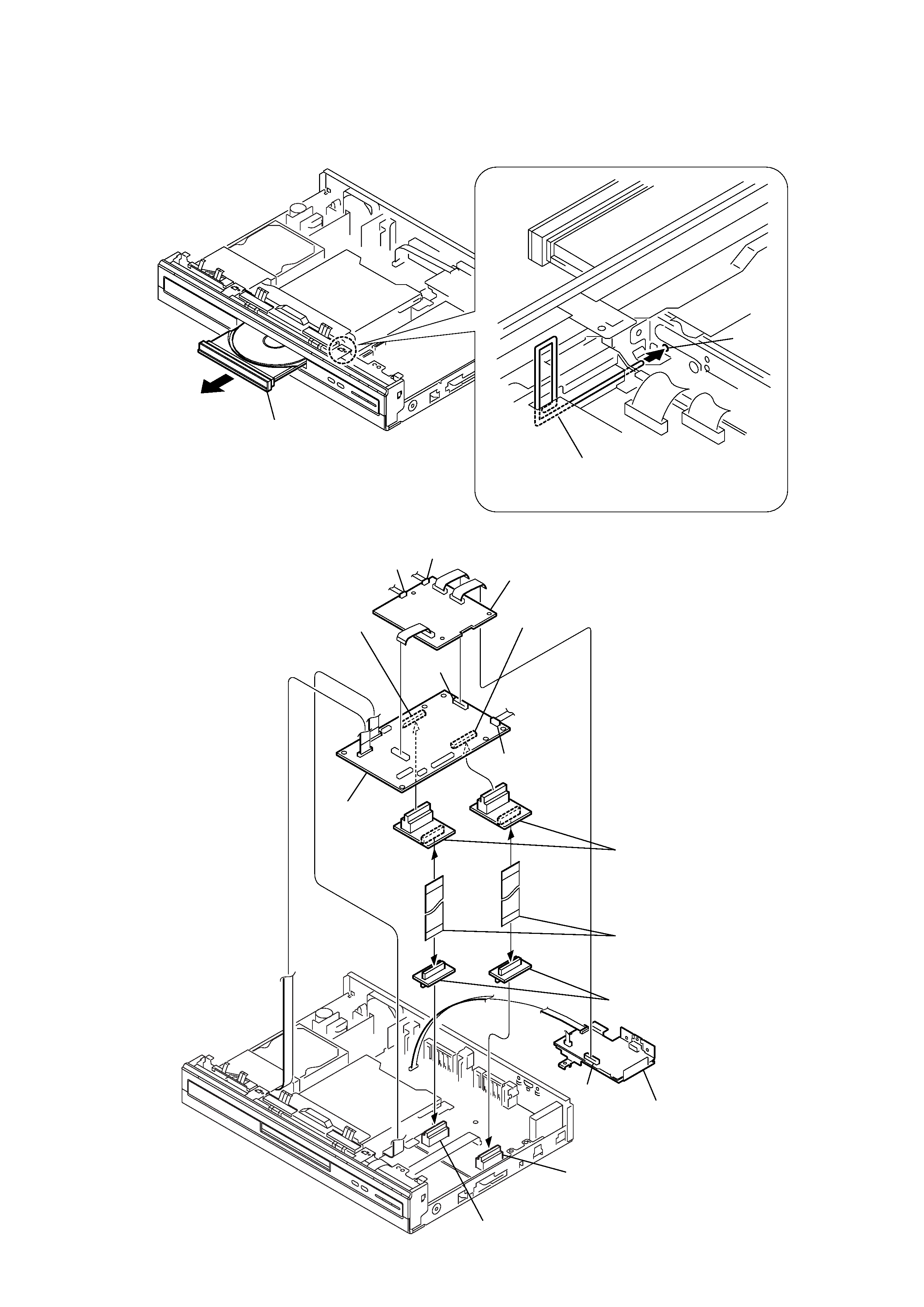
1. DISK REMOVAL PROCEDURE IF THE TRAY CANNOT BE EJECTED (FORCED EJECTION)
1.
Remove the upper case.
2.
Insert the stiff wire in the hole and eject the tray.
Open the tray.
The stiff wire.
Hole
Fig. 1
Fig. 2
2. BOARDS CONNECTION
Connector (CN1701)
Connector (CN1702)
Connector (CN501)
Two RD51-AV extension flexible flat cables
Two RD51-AV relay boards
RD-58 board
UE-001 board
Two RD51-AV relay boards
Connector (CN502)
MI-056 board, MI pwb bracket
CN501
CN1901
CN2101
CN101
CN104