RCD-W7V
US Model
COMPACT DISC RECORDER
SERVICE MANUAL
SPECIFICATIONS
Model Name Using Similar Machanism RCD-W1
CD Mechanism Type
CDM-700(CD-RW)
Optical Pick-up Type
KRS-220C
Model Name Using Similar Mechanism NEW
CD/DVD Mechanism Type
DP-4RM
CD-R
CD/DVD
9-873-470-03
2002I0200-1
© 2002.09
Sony Corporation
Home Audio Company
Published by Sony Engineering Corporation
DECK A (the CD/DVD player section)
System
CD/DVD player
Laser
Semiconductor laser
Signal format system
NTSC
Playable discs
DVD, CD, CD-R/CD-RW
(for music use), MP3 disc
Frequency response
DVD (PCM 96 kHz):
20 Hz to 44 kHz (
±1.0 dB)
DVD (PCM 48 kHz):
20 Hz to 22 kHz (
±0.5 dB)
CD: 20 Hz to 20 kHz
(
±0.5 dB)
Signal-to-noise ratio
More than 100dB
(ANALOG OUT connectors only)
Harmonic distortion
Less than 0.015%
Dynamic range
More than 95 dB (DVD)
More than 95 dB (CD)
Wow and flutter
Less than detected value
(
±0.001% W PEAK)
Outputs
VIDEO OUT
1.0 Vp-p 75 ohms,
sync negative
S-VIDEO OUT
Luminance signal:
1.0 Vp-p, 75 ohms
C: 0.3 Vp-p, 75 ohms
COMPONENT VIDEO OUT
Y: 1.0 Vp-p, 75 ohms,
sync negative
(Phono jacks)
CB/B-Y, CR/R-Y:
0.7 Vp-p, 75 ohms
DECK B (the CD-R and CD-RW recording section)
System
Compact disc digital audio system
Laser
Semiconductor laser
Playable discs
CD, CD-R, CD-RW (for music use)
Frequency response
20 Hz to 20,000 Hz (
±0.5 dB)
Signal-to-noise ratio
Over 100 dB during playback
Dynamic range
More than 95 dB during playback
Input
ANALOG IN (Phono jacks)
Impedance 47 kilohms,
Rated input 330 mVrms
DIGITAL OPTICAL IN
Optical wavelength 660 nm
(Square optical connector jack)
Outputs
ANALOG OUT (Phono jacks) Impedance 47 kilohms, Rated input
2 Vrms
Load impedance over 10 kilohms
DIGITAL OPTICAL OUT
Wavelength 660 nm
(Square optical connector jack)
Output level -18 dBm
PHONES (Phone jacks)
28 mW, 32 ohms
General
Power requirements
120 V AC, 60 Hz
Power consumption
25W (120 V AC)
Dimensions (approx.)
430 x 107.5 x 370 mm (w/h/d) incl.
projecting parts
Mass (approx.)
5.1 kg
Supplied accessories
Design and specifications are subject to change without notice.
· Video cord (1)
· Audio cords (2)
· Remote commander (remote) RM-R70 (1)
· R6 (size AA) batteries (2)
Ver 1.2 2002.09
2
RCD-W7V
SAFETY CHECK-OUT
After correcting the original service problem, perform the follow-
ing safety checks before releasing the set to the customer:
Check the antenna terminals, metal trim, "metallized" knobs, screws,
and all other exposed metal parts for AC leakage. Check leakage as
described below.
LEAKAGE
The AC leakage from any exposed metal part to earth Ground and
from all exposed metal parts to any exposed metal part having a
return to chassis, must not exceed 0.5 mA (500 microampers). Leak-
age current can be measured by any one of three methods.
1. A commercial leakage tester, such as the Simpson 229 or RCA
WT-540A. Follow the manufacturers' instructions to use these
instruments.
2. A battery-operated AC milliammeter. The Data Precision 245
digital multimeter is suitable for this job.
3. Measuring the voltage drop across a resistor by means of a VOM
or battery-operated AC voltmeter. The "limit" indication is 0.75
V, so analog meters must have an accurate low-voltage scale.
The Simpson 250 and Sanwa SH-63Trd are examples of a pas-
sive VOM that is suitable. Nearly all battery operated digital
multimeters that have a 2V AC range are suitable. (See Fig. A)
SAFETY-RELATED COMPONENT WARNING !!
COMPONENTS IDENTIFIED BY MARK
! OR DOTTED LINE
WITH MARK
! ON THE SCHEMATIC DIAGRAMS AND IN
THE PARTS LIST ARE CRITICAL TO SAFE OPERATION.
REPLACE THESE COMPONENTS WITH SONY PARTS
WHOSE PART NUMBERS APPEAR AS SHOWN IN THIS
MANUAL OR IN SUPPLEMENTS PUBLISHED BY SONY.
Notes on chip component replacement
· Never reuse a disconnected chip component.
· Notice that the minus side of a tantalum capacitor may be
damaged by heat.
Flexible Circuit Board Repairing
· Keep the temperature of soldering iron around 270°C
during repairing.
· Do not touch the soldering iron on the same conductor of the
circuit board (within 3 times).
· Be careful not to apply force on the conductor when soldering
or unsoldering.
NOTES ON HANDLING THE OPTICAL PICK-UP
BLOCK OR BASE UNIT
The laser diode in the optical pick-up block may suffer electrostatic
break-down because of the potential difference generated by the
charged electrostatic load, etc. on clothing and the human body.
During repair, pay attention to electrostatic break-down and also
use the procedure in the printed matter which is included in the
repair parts.
The flexible board is easily damaged and should be handled with
care.
NOTES ON LASER DIODE EMISSION CHECK
The laser beam on this model is concentrated so as to be focused on
the disc reflective surface by the objective lens in the optical pick-
up block. Therefore, when checking the laser diode emission, ob-
serve from more than 30 cm away from the objective lens.
CAUTION
Use of controls or adjustments or performance of procedures
other than those specified herein may result in hazardous ra-
diation exposure.
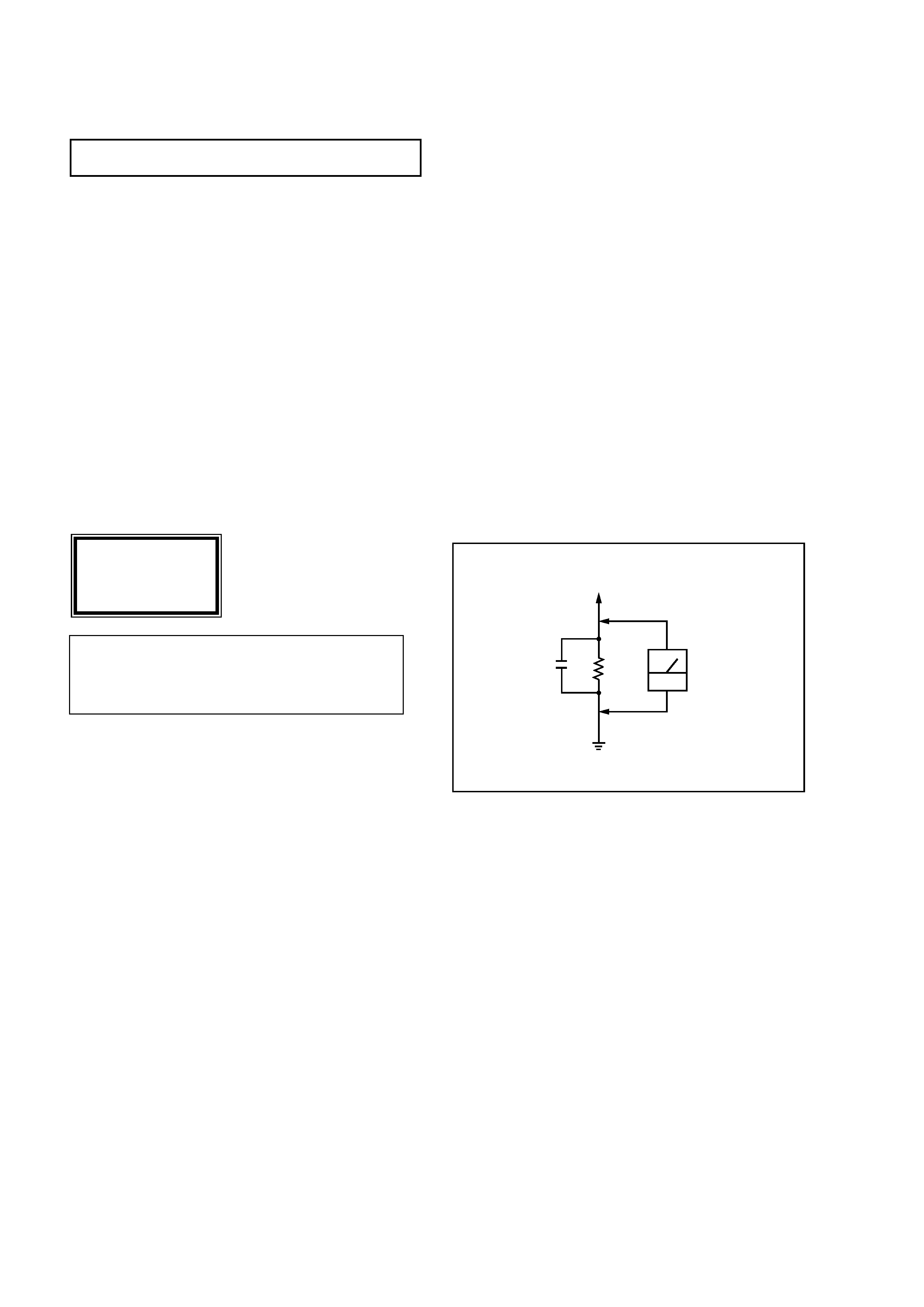
Fig. A. Using an AC voltmeter to check AC leakage.
0.15
µF
To Exposed Metal
Parts on Set
1.5k
AC
voltmeter
(0.75V)
Earth Ground
CAUTION
The use of optical instruments with this product will increase eye
hazard.As the laser beam used in this Compact Disc Recorder is
harmful to eyes, do not attempt to disassemble the cabinet.
Refer servicing to qualified personnel only.
This label is located on the rear
panel of your recorder .
CAUTION
VISIBLE LASER RADIATION
WHEN OPEN AND
INTERLOCK DEFEATED.
DO NOT STARE INTO BEAM.

3
RCD-W7V
TABLE OF CONTENTS
1. SERVICING NOTE .......................................................... 4
2. GENERAL .......................................................................... 8
3. DISASSEMBLY
3-1. Top Case ............................................................................... 9
3-2. Tray Door, Front Panel Assy .............................................. 10
3-3. HP board, FL board, VOL board ........................................ 10
3-4. Back Panel ......................................................................... 11
3-5. Audio Board ....................................................................... 11
3-6. Power Board ...................................................................... 12
3-7. DVD Deck Assy (Deck A), CD-R Deck Assy (Deck B) ... 12
3-8. BD Board (Deck A) ........................................................... 13
3-9. Sled Base Assy (Deck A) ................................................... 13
3-10.CD-R Board (Deck B) ........................................................ 14
3-11.PU Mechanism Assy (Deck B) ........................................... 14
4. TEST MODE ...................................................................... 15
5. ELECTRICAL ADJUSTMENT ................................... 16
6. DIAGRAMS
6-1. Circuit Boards Location .................................................... 23
6-2. Block diagrams Overall Section ................................. 24
Block diagrams CD/DVD Section .............................. 25
Block diagrams CD-RW Section ................................ 26
Block diagrams I/O Section ........................................ 27
Block diagrams Power Section ................................... 28
6-3. Schematic Diagram BD Section (1/5) ......................... 29
6-4. Schematic Diagram BD Section (2/5) ......................... 30
6-5. Schematic Diagram BD Section (3/5) ......................... 31
6-6. Schematic Diagram BD Section (4/5) ......................... 32
6-7. Schematic Diagram BD Section (5/5) ......................... 33
6-8. Printed Wiring Board BD Section (Side A) ................ 34
Printed Wiring Board BD Section (Side B) ................ 35
6-9. Schematic Diagram BD-R Section (1/4) .................... 36
6-10. Schematic Diagram BD-R Section (2/4) .................... 37
6-11. Schematic Diagram BD-R Section (3/4) .................... 38
6-12. Schematic Diagram BD-R Section (4/4) .................... 39
6-13. Printed Wiring Board BD-R Section (Side A) ............ 40
Printed Wiring Board BD-R Section (Side B) ............. 41
6-14. Printed Wiring Board Audio Section ........................... 42
6-15. Schematic Diagram Audio Section ............................ 43
6-16. Printed Wiring Board Display Section ........................ 44
6-17. Schematic Diagram Display Section ........................... 45
6-18. Schematic Diagram Power Section ............................. 46
6-19. Printed Wiring Board Power Section .......................... 47
6-20. IC Pin Functions ................................................................ 48
6-21. IC Block Diagrams ............................................................ 54
7. EXPLODED VIEWS
7-1. Front Panel Section ............................................................. 56
7-2. Chassis Section ................................................................... 57
7-3. DVD Play Section (Deck A) (DP-4RM) ............................. 58
7-4. CD Record Section (Deck B) (CDM-700(CD-RW)) .......... 59
8. ELECTRICAL PARTS LIST
................................. 60
ERROR MESSAGE
The following table explains the error
messages that appear in the display.
CHECK DISC
, A record-related button has been pressed
when a finalized disc is in the DECK B.
, A record-related button has been pressed
when a standard CD is in the DECK B.
, An unplayable disc (CD-ROM, Video CD etc.) is inserted.
DATA DISC
, A non-audio CD-ROM or a CD-Video disc has been
placed in the machine.
DISC ERROR
, An unfinalized disc has been placed in the DECK A.
, A DVD disc has been placed in the DECK B .
, The disc is not seated properly.
, There is a problem with the disc.
DISC FULL
, There is not enough time left on the disc to complete a
planned recording.
ERROR
, The disc tray is not seated properly.
NO AUDIO
, A record-related button has been pressed
when a non-audio disc is in the DECK B.
CAN NOT COPY
, A recording is not possible due to the Serial
Copy Management System (SCMS).
UNLOCK
, There is not source for recording through
DIGITAL OPTICAL IN jack.
NO DISC
, No disc is inserted in the recorder.
4
RCD-W7V
SECTION 1
SERVICING NOTE
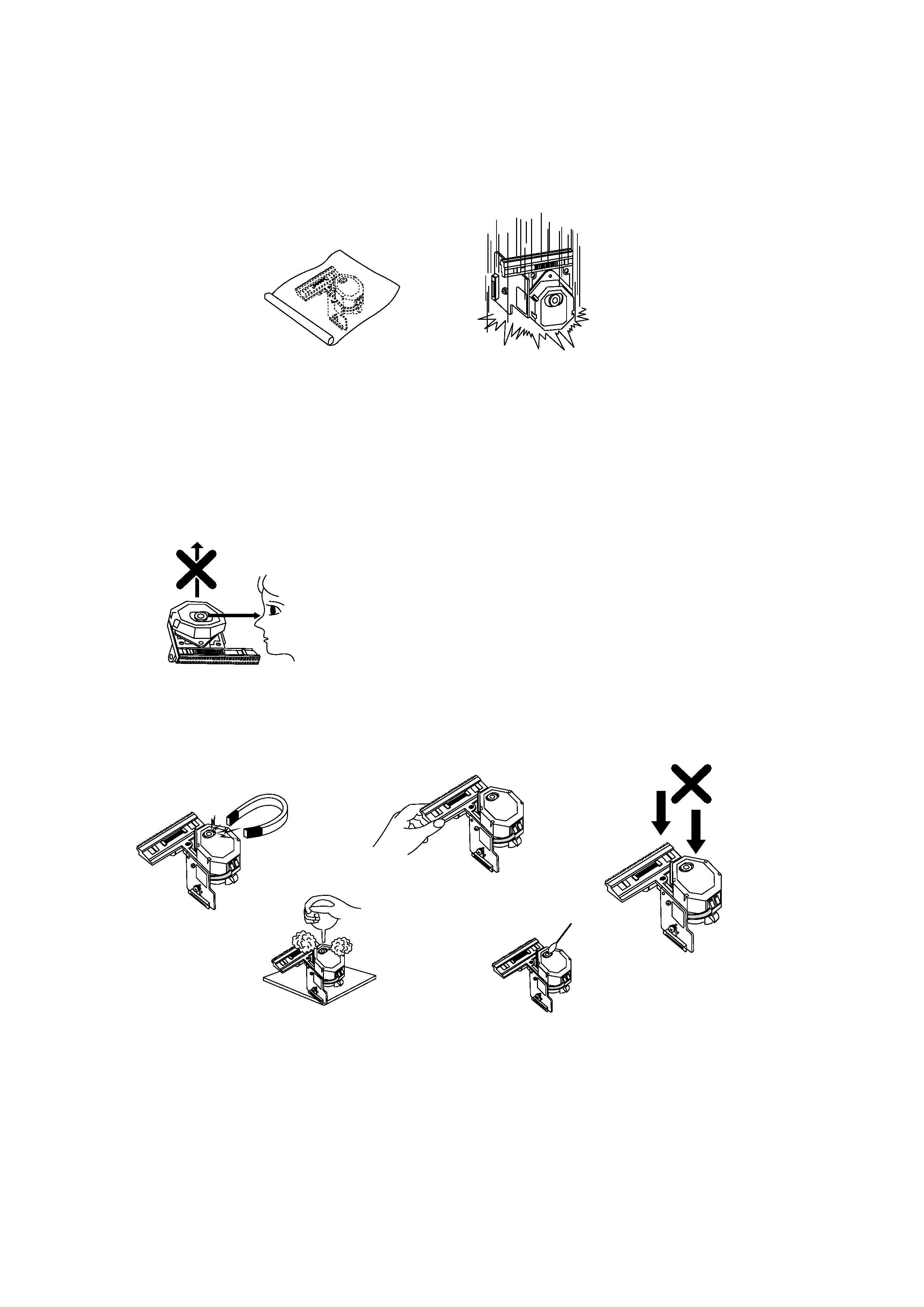
NOTES REGARDING HANDLING OF THE PICK-UP
1. Notes for transport and storage
1) The pick-up should always be left in its conductive bag until immediately prior to use.
2) The pick-up should never be subjected to external pressure or impact.
2. Repair notes
1) The pick-up incorporates a strong magnet, and so should never be brought close to magnetic materials.
2) The pick-up should always be handled correctly and carefully , taking care to avoid external pressure and impact.
If it is subjected to pressure or impact, the result may be an operational malfunction and/or damage to the
printed-circuit board.
3) Each and every pick-up is already individually adjusted to a high degree of precision, and for that reason the
adjustment point and installation screws should absolutely never be touched.
4) Laser beams may damage the eyes!
Absolutely never permit laser beams to enter the eyes!
Also NEVER switch ON the power to the laser output part (lens, etc.) of the pick-up if it is damaged.
5) Cleaning the lens surface
If there is dust on the lens surface, the dust should be cleaned away by using an air bush (such as used for
camera lens). The lens is held by a delicate spring. When cleaning the lens surface, therefore, a cotton swab
should be used, taking care not to distort this.
6) Never attempt to disassemble the pick-up.
Spring by excess pressure. If the lens is extremely dirty, apply isopropyl alcohol to the cotton swab. (Do not use any
other liquid cleaners, because they will damage the lens.) Take care not to use too much of this alcohol on the swab,
and do not allow the alcohol to get inside the pick-up.
Storage in conductive bag
NEVER look directly at the laser beam, and don't let contact
fingers or other exposed skin.
Magnet
How to hold the pick-up
Conductive Sheet
Cotton swab
Pressure
Pressure
Drop impact
5
RCD-W7V
NOTES REGARDING COMPACT DISC PLAYER REPAIRS
1. Preparations
1) Compact disc players incorporate a great many ICs as well as the pick-up (laser diode). These compo-
nents are sensitive to, and easily affected by, static electricity. If such static is high voltage, components
can be damaged, and for that reason components should be handled with care.
2) The pick-up is composed of many optical components and other high-precision components. Care must
be taken, therefore, to avoid repair or storage where the temperature of humidity is high, where strong
magnetism is present, or where there is excessive dust.
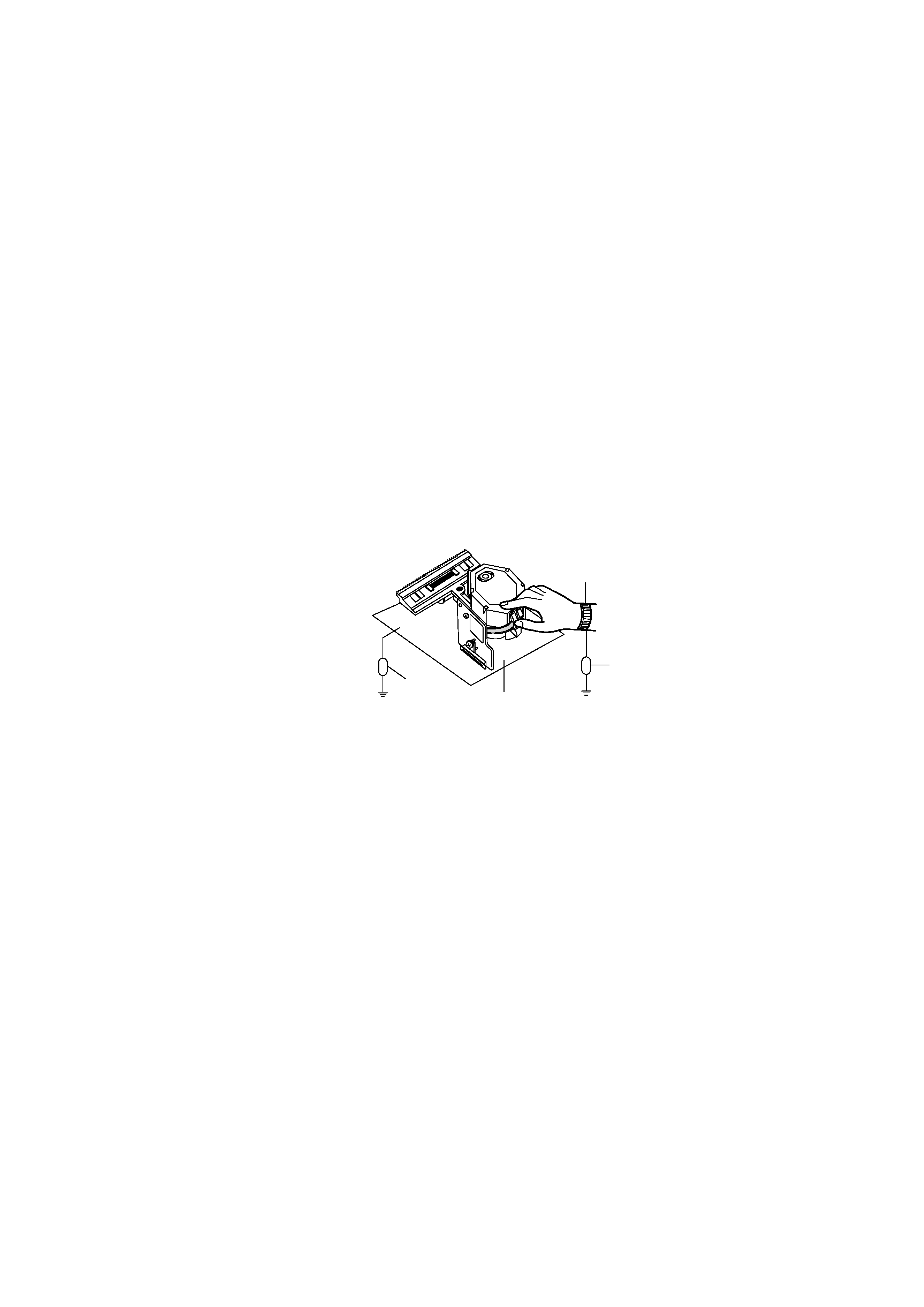
2. Notes for repair
1) Before replacing a component part, first disconnect the power supply lead wire from the unit
2) All equipment, measuring instruments and tools must be grounded.
3) The workbench should be covered with a conductive sheet and grounded.
When removing the laser pick-up from its conductive bag, do not place the pick-up on the bag. (This is
because there is the possibility of damage by static electricity.)
4) To prevent AC leakage, the metal part of the soldering iron should be grounded.
5) Workers should be grounded by an armband (1M
)
6) Care should be taken not to permit the laser pick-up to come in contact with clothing, in order to prevent
static electricity changes in the clothing to escape from the armband.
7) The laser beam from the pick-up should NEVER be directly facing the eyes or bare skin.
Resistor
(1M
)
Conductive
Sheet
Resistor
(1M
)
Armband