5th Edition
Published in Japan c.12.2001 9-927-088-03

Notice
This manual is copyrighted by Sony Computer Entertainment Inc. All rights Reserved.
No re-produced or transferred required except permission by Sony Computer
Entertainment Inc.
No commercial use and rental required.
Revisions
This manual compiled by 5th edition of SCPH-100's Design data.
Design and specifications will be subject to change without notice.
So, the latest versions of Service Manual, Technical Memo and SCEI. Service Promotion
Dept.'s Home Page "PS SERVICE PLAZA" should be used together with this manual.
PS SERVICE PLAZA web site: http://svc.scei.sony.co.jp/
2
3
1. SPECIFICATIONS ........................................................................................ 1-1
2. EXPLODED VIEW
2-1. Main Block ..................................................................................................... 2-1
3. ADJUSTMENTS
3-1. Check Specification ....................................................................................... 3-1
3-2. Adjustment & Check Tool .............................................................................. 3-2
3-3. Attention ......................................................................................................... 3-2
4. BLOCK DIAGRAM
4-1. Overall Block Diagram (PM-41 (-11/-21/-31/-41/-51/-61) Board) ................ 4-1
4-2. Overall Block Diagram (PM-41 (-71) Board) ................................................ 4-3
5. DIAGRAMS
5-1. Printed Wiring Board (PM-41 (-11) Board) (SCPH-100) .............................. 5-1
5-2. Printed Wiring Board (PM-41 (-21/-31) Board) (SCPH-100/101/102) ......... 5-3
5-3. Printed Wiring Board (PM-41 (-41/-51) Board) (SCPH-100/101/102/103) .. 5-5
5-4. Printed Wiring Board (PM-41 (-61) Board) (SCPH-100/101/102/103) ........ 5-7
5-5. Printed Wiring Board (PM-41 (-71) Board) (SCPH-100/101/102/103) ........ 5-9
5-6. Schematic Diagram (PM-41 (-11/-21/-31/-41/-51/-61) Board (1/15)) ......... 5-11
5-7. Schematic Diagram (PM-41 (-71) Board (2/15)) ......................................... 5-13
5-8. Schematic Diagram (PM-41 (-11/-21/-31) Board (3/15)) ............................ 5-15
5-9. Schematic Diagram (PM-41 (-41/-51) Board (4/15)) .................................. 5-17
5-10. Schematic Diagram (PM-41 (-61) Board (5/15)) ......................................... 5-19
5-11. Schematic Diagram (PM-41 (-71) Board (6/15)) ......................................... 5-21
5-12. Schematic Diagram (PM-41 (-11/-21/-31/-41/-51/-61) Board (7/15)) ......... 5-23
5-13. Schematic Diagram (PM-41 (-71) Board (8/15)) ......................................... 5-25
5-14. Schematic Diagram (PM-41 (-11/-21/-31/-41/-51/-61) Board (9/15)) ......... 5-27
5-15. Schematic Diagram (PM-41 (-71) Board (10/15)) ....................................... 5-29
5-16. Schematic Diagram (PM-41 (-11) Board (11/15)) ....................................... 5-31
5-17. Schematic Diagram (PM-41 (-21/-31/-41/-51/-61) Board (12/15)) ............. 5-33
5-18. Schematic Diagram (PM-41 (-71) Board (13/15)) ....................................... 5-35
5-19. Schematic Diagram (PM-41 (-11/-21/-31/-41/-51/-61) Board (14/15)) ....... 5-37
5-20. Schematic Diagram (PM-41 (-71) Board (15/15)) ....................................... 5-39
6. ELECTRICAL PARTS LIST
· PM-41 Board ......................................................................................................... 6-1
Reproduction prohibited
TABLE OF CONTENTS
Reproduction prohibited

Reproduction prohibited
Reproduction prohibited
1-1
SECTION 1
SPECIFICATIONS
General
Power requirements
DC IN 7.5 V
Power consumption
9 W
Dimensions
193
× 36 × 143 mm (w/h/d)
Mass
550 g
Operating Temperature
5°C - 35°C
Laser diode properties
· Material : GaAlAs
· Wavelength : l=780 nm
· Emission duration : Continuous
· Laser output : Less than 44.6 µW
(measured at a distance of 200 mm
from the lens surface on the optical
pick-up block)
Inputs/outputs on the front
Controller ports (2)
MEMORY CARD slots (2)
Outputs on the rear
AV MULTI OUT connector (1)
AC power adaptor
Power requirements
100 V AC, 50/60 Hz
Output voltage and current
7.5 V, 2.0 A max.
Dimensions
50
× 27 × 78 mm (w/h/d)
Mass
160 g
SCPH-100
Supplied accessories
AC Adaptor (1)
AV Cable
(integrated audio/video) (1)
Analog Controller
(DUALSHOCKTM) (1)
Instruction Manual (1)
Design and specifications are subject to
change without notice.
General
Power requirements
DC IN 7.5 V
Power consumption
9 W
Dimensions
193
× 38 × 144 mm (w/h/d)
(7 5/8
× 1 1/2 × 5 3/4 inches)
Mass
560 g (1 lb 3 oz)
Operating Temperature
41°F - 95°F (5°C - 35°C)
Laser diode properties
· Material : GaAlAs
· Wavelength : l=780 nm
· Emission duration : Continuous
· Laser output : Less than 44.6 µW
(measured at a distance of 200 mm
from the lens surface on the optical
pick-up block)
Inputs/outputs on the front
Controller ports (2)
MEMORY CARD slots (2)
Outputs on the rear
AV MULTI OUT connector (1)
Supplied accessories
AC Adaptor (1)
AV Cable
(integrated audio/video) (1)
Analog Controller
(DUALSHOCKTM) (1)
Instruction Manual (1)
SCPH-101
Design and specifications are subject to
change without notice.
General
Power requirements
DC IN 7.5 V
Power consumption
9 W
Dimensions
193
× 38 × 144 mm (w/h/d)
Mass
560 g
Operating Temperature
41°F - 95°F (5°C - 35°C)
Laser diode properties
· Material : GaAlAs
· Wavelength : l=780 nm
· Emission duration : Continuous
· Laser output : Less than 44.6 µW
(measured at a distance of 200 mm
from the lens surface on the optical
pick-up block)
Inputs/outputs on the front
Controller ports (2)
MEMORY CARD slots (2)
Outputs on the rear
AV MULTI OUT connector (1)
Supplied accessories
AC Adaptor (1)
AV Cable
(integrated audio/video) (1)
Analog Controller
(DUALSHOCKTM) (1)
Instruction Manual (1)
SCPH-102
Design and specifications are subject to
change without notice.
General
Power requirements
DC IN 7.5 V
Power consumption
9 W
Dimensions
193
× 38 × 144 mm (w/h/d)
Mass
560 g
Operating Temperature
5°C - 35°C
Laser diode properties
· Material : GaAlAs
· Wavelength : l=780 nm
· Emission duration : Continuous
· Laser output : Less than 44.6 µW
(measured at a distance of 200 mm
from the lens surface on the optical
pick-up block)
Inputs/outputs on the front
Controller ports (2)
MEMORY CARD slots (2)
Outputs on the rear
AV MULTI OUT connector (1)
Supplied accessories
AC Adaptor (1)
AV Cable
(integrated audio/video) (1)
Analog Controller
(DUALSHOCKTM) (1)
Instruction Manual (1)
SCPH-103
Design and specifications are subject to
change without notice.
1-2
Reproduction prohibited
Reproduction prohibited
2-1
2-2
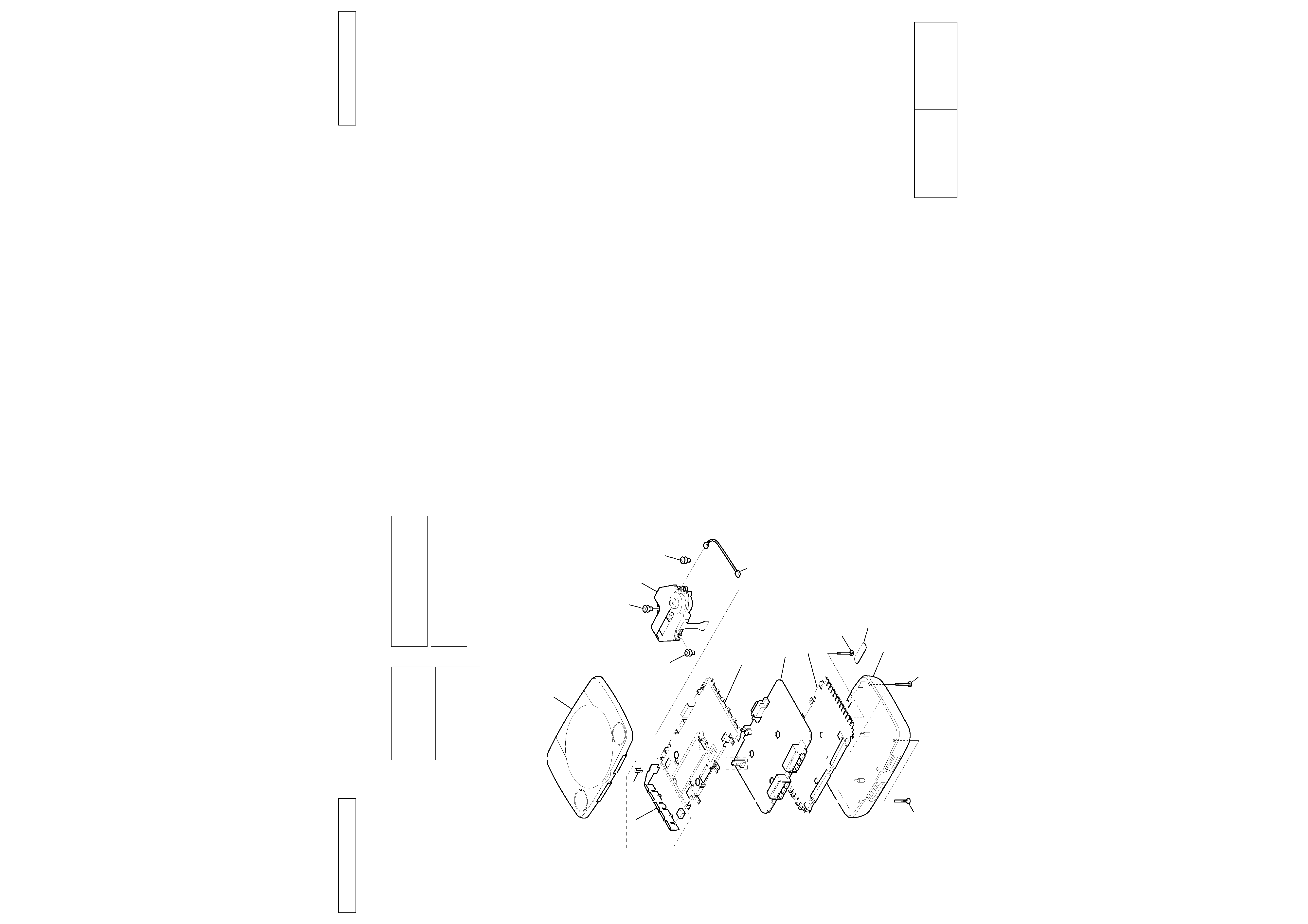
SECTION 2
EXPLODED VIEW
NOTE:
· The mechanical parts with no reference
number in the exploded views are not supplied.
· -XX and -X mean standardized parts, so
they may have some difference from the
original one.
· Accessories and packing materials are given in
the last of this parts list.
NOTE:
· SC Classification :
S : Stocked parts
U : Unsupplied parts
O : Ordered parts
2-1. MAIN BLOCK
The components identified by
mark 0 or dotted line with mark.
0 are critical for safety.
Replace only with part number
specified.
Les composants identifiés par une
marque 0 sont critiques pour
la sécurité.
Ne les remplacer que par une piéce
portant le numéro spécifié.
CAUTION
Use of controls or adjustments or performance of
procedures other than those specified herein may
result in hazardous rediation exposure.
The components identified by
mark 0 or dotted line with mark.
0 are critical for safety.
Replace only with part number
specified.
Les composants identifiés par une
marque 0 sont critiques pour la
sécurité.
Ne les remplacer que par une piéce
portant le numéro spécifié.
SC
Ref. No.
Part No.
Description
Remark
2.6X16
2.6X16
Lower
B-shield
PM-41
PM
A-shield
BAM
INSU
INSU
(-11)
(-11)
INSU
Clip
Heat Sink
Upper
2.6X16
Void
O
A-shield
X-3950-906-1
SHIELD (A) ASSY (-11/-21/-31/-41/-51/-61)
O
A-shield
X-3952-077-1
SHIELD (A) ASSY (-71)
O
B-shield
3-063-429-01
SHIELD (B) (-11/-21/-31/-41/-51/-61)
O
B-shield
3-069-803-01
SHIELD (B) (-71)
S0
BAM
8-820-135-01
DEVICE, OPTICAL KSM-440BAM/C1NP
O
Clip
3-063-704-01
CLIP (-11)
O
Heat Sink
3-063-703-01
HEAT SINK (-11)
S
INSU
3-063-428-01
INSULATOR (A) (-11)
S
INSU
3-965-376-11
INSULATOR (-21/-31/-41/-51/-61/-71)
O
Lower
X-3952-076-1
CABINET (LOWER) ASSY (100,102,103)
O
Lower
X-3952-079-1
CABINET (LOWER) ASSY (101)
O
PM
1-954-377-31
HARNESS (PM-86)
O0
PM-41
A-6713-742-A
PM-41 BOARD, COMPLETE (100:-11/-21/-31)
O0
PM-41
A-6713-768-A
PM-41 BOARD, COMPLETE (101:-21/-31)
O0
PM-41
A-6713-776-A
PM-41 BOARD, COMPLETE (102:-21/-31)
O0
PM-41
A-6713-853-A
PM-41 BOARD, COMPLETE (100:-41/-51)
O0 PM-41
A-6713-854-A
PM-41 BOARD, COMPLETE (101:-41/-51)
O0 PM-41
A-6713-855-A
PM-41 BOARD, COMPLETE (102:-41/-51)
O0 PM-41
A-6713-864-A
PM-41 BOARD, COMPLETE (103:-41/-51)
O0 PM-41
A-6713-902-A
PM-41 BOARD, COMPLETE (101:-61)
O0 PM-41
A-6713-903-A
PM-41 BOARD, COMPLETE (100:-61)
O0 PM-41
A-6713-904-A
PM-41 BOARD, COMPLETE (102:-61)
O0 PM-41
A-6713-906-A
PM-41 BOARD, COMPLETE (103:-61)
O0 PM-41
A-6715-470-A
PM-41 BOARD, COMPLETE (100:-71)
O0 PM-41
A-6715-471-A
PM-41 BOARD, COMPLETE (101:-71)
O0 PM-41
A-6715-483-A
PM-41 BOARD, COMPLETE (102:-71)
O0 PM-41
A-6715-484-A
PM-41 BOARD, COMPLETE (103:-71)
O
Upper
X-3952-075-1
CABINET (UPPER) ASSY (100,102,103)
O
Upper
X-3952-078-1
CABINET (UPPER) ASSY (101)
O
Void
3-064-752-01
TAPE, VOID (100)
O
Void
3-065-630-01
TAPE (B), VOID (101)
O
Void
3-065-656-01
TAPE (C), VOID (102)
O
Void
3-066-884-02
TAPE (D), VOID (103)
O
Void
3-075-101-01
TAPE (KR3), VOID (103D)
O
2.6X16
3-063-705-01
SCREW (2.6X16), TAPPING
Reproduction prohibited
Reproduction prohibited
3-1
3-2
3-1
3-2
3-2. ADJUSTMENT & CHECK TOOL
SCD-2700 TEST DISC
(J-2504-010-A)
QA DISC
PTPX-97001
for Japan & Asia area.
(J-2504-013-A)
PUPX-93001
for USA & Canada area.
(J-2504-009-A)
PEPX-94001
for Europe, Australia, Galf area.
(J-2504-007-A)
AGING DISC
PTPX-97002
for Japan & Asia area.
(J-2504-019-A)
PUPX-93002
for USA & Canada area.
(J-2504-020-A)
PEPX-94002
for Europe, Australia, Galf area.
(J-2504-017-A)
ANALOG CONTROLLER SERVICE DISC
PTPX-97012
for Japan & Asia area.
(J-2504-021-A)
PUPX-93010
for USA & Canada area.
(J-2504-022-A)
PEPX-94009
for Europe, Australia, Galf area.
(J-2504-023-A)
ANALOG CONTROLLER CHECKER (PRE-H3000)
(J-2504-008-A)
SWITCH ON JIG (PRJ-001)
(J-2504-003-A)
3-3. ATTENTION
Dielectric voltage withstand of Optical Device.
After repair complete. Dielectric voltage withstand test and Insulation resistance test to be conducted
according to the regulation of IEC-65 EN60065 or UL1492 or
.
About replacement of Optical Device.
Check the specification of RF level, Jitter, Eye pattern, Focus gain and Tracking error using Check jig before
replaceing the Optical Device.
When Optical Device satisfied those specification, Playback QA DISC or AGING DISC for checking double
speed ability and sleding mechanism.
SECTION 3
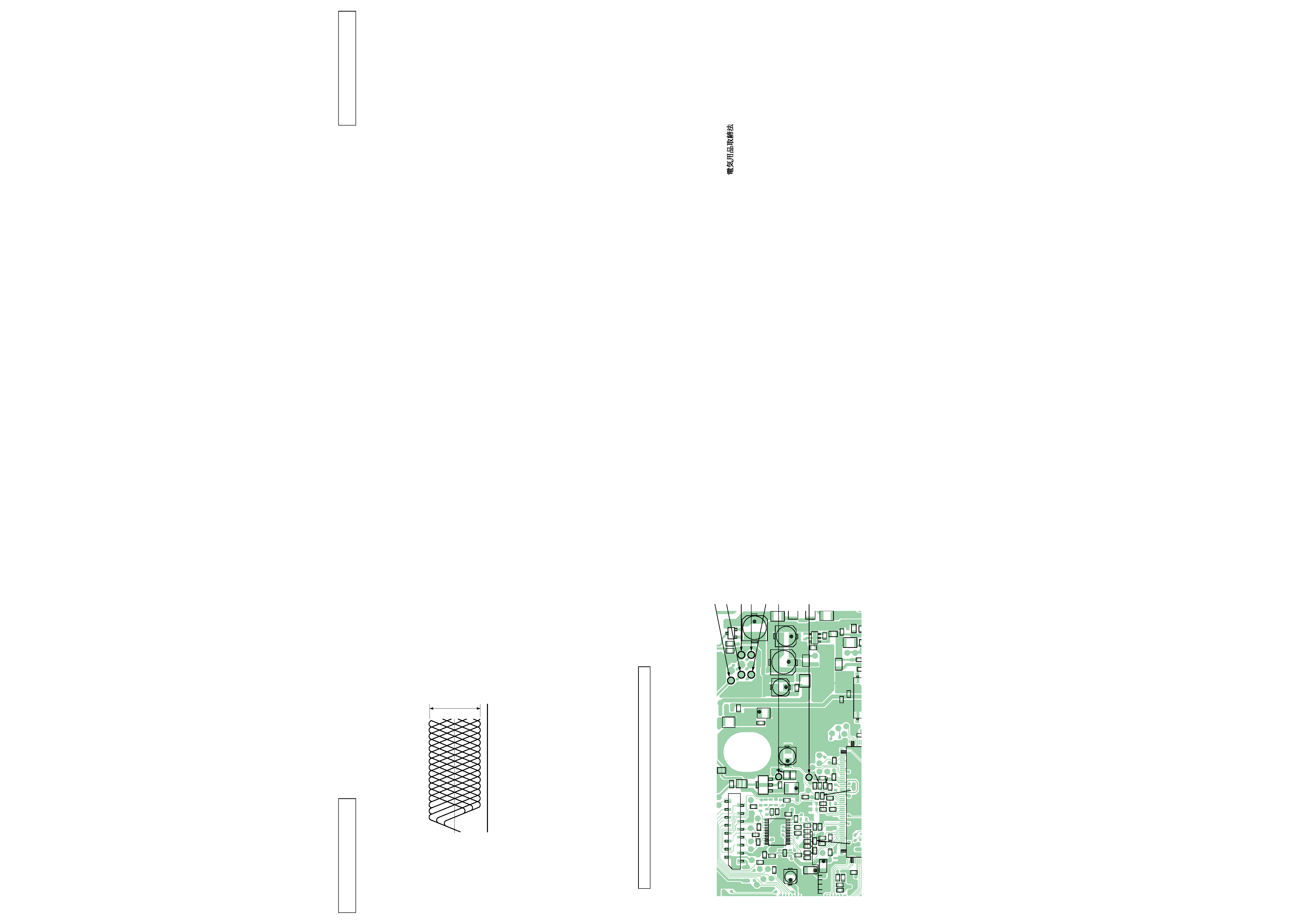
ADJUSTMENTS
3-1. CHECK SPECIFICATION
· RF signal waveform (eye pattern)
VOLT/DIV : 0.2 V
TIME/DIV : 500 nS
0.90 to 1.35 Vp-p
0V
Use SCD-2700 DISC when measured RF level.
Use the oscilloscope with input impedance more than 10 M
.
Check Point for PU-41 Board. (Refer to each printed wiring boards)
3-1
3-2
RF level
0.90 to 1.35 Vp-p (Check point : Between CL704 (HOT) and CL710 (VC).)
RF Jitter
Below 9.0 nS (Measuring by KJM-6135S JITTER METER.)
Below 27.0 nS (Measuring by KJM-6235S JITTER METER.)
PP level
1.1 ± 0.6 Vp-p (Check point : Between CL776 (HOT) and CL710 (VC).)
Use LPF (fc = 10 kHz)
Tracking level
1.25 ± 0.65 Vp-p (Check point : Between CL709 (HOT) and CL710 (VC).)
Caution.
Vc Line (CL710) do not make common use with GND line.
Q003
C605
L601
PS004
PS601
PS603
C618
L604
C316
C658
C768
C701
C740
C741
C762
R745
C737
R739
C738
R712
C729
C715
C728
C725
C726
R793
R770
R710
R714
R733
C714
R740
R738
R775
C720
R727
R732
C743
R717
L701
R642
C704
R703
FB602
R014
R015
C639
C600
C637
C657
R701
CN702
R746
C763
R748
C742
Q701
R750
C739
R749
R747
C705
C611
R705
R704
C703
C706
R774
R783
C761
C709
R706
C774
C744
R702
R723
R734
C736
IC723
C731
R795
R741
R769
FB710
C656
C617
IC602
C641
C635
C609
C659
C608
L607
L606
L608
L106
C648
C647
FB003
21
1
1
2
15
16
10
20
11
20
1
3
5
4
52
1
208
53
CL727 (Iop)
CL728 (Iop)
CL776 (HOT) (PP level)
CL709 (HOT) (Tracking level)
CL710 (VC)
CL706 (GND)
CL704 (HOT) (RF level)