1
SERVICE MANUAL
STEREO TURNTABLE SYSTEM
US Model
AEP Model
UK Model
E Model
PS-DJ9000
SPECIFICATIONS
Motor and Platter
Drive system
Direct drive quartz
Motor
3 phase 8 pole Brushless DC motor
Platter
Aluminum die-cast
Diameter 332 mm (13.1 inches)
Weight 750 g (1.85 lbs)
Speeds
33
and 45 rpm
1/3
Wow and flutter
Less than 0.15 % (WRMS)
Signal to noise ratio
More than 55 dB (DIN-B)
Tone Arm
Type
Static balanced S-shaped tonearm with
detachable headshell
Effective arm length
230 mm
Overhang
15 mm
Usable cartridge weight
4 g (min.) to 10 g (max.)
General
Power requirements
U.S.A. and Mexico: 120 V AC, 60 Hz
European countries: 220 - 230 V AC,
50/60 Hz
Other countries: 110 - 120 V/
220 - 240 V AC, 50/60 Hz
Power consumption
15 W
Dimensions
Approx. 450
× 152 × 352 mm (17
×
11/16
5
× 13
in) (w/h/d)
11/16
3/4
Mass
10 kg (22 lbs)
Supplied Accessories
Platter (2)
Slip mat (2)
Dust cover (with hinges) (2)
Counterweight (2)
Cartridge and headshell (2)
45 adaptor (2)
Audio cord (with ground wire) (2)
AC power cord (2)
Design and specifications are subject to change without
notice.
Replacing the Cartridge
The life expectancy of the stylus tip is about 500 hours.
To maintain optimum sound quality and prevent
damage to your records, we recommend replacing the
cartridge before the end of this time duration.
Obtain a replacement cartridge from your Sony dealer.
This set is the stereo turntable in
PMPK-DJ9000.
9-929-553-12
2001F0200-1
© 2001.6
Sony Corporation
Home Audio Company
Shinagawa Tec Service Manual Production Group
Ver 1.1 2001. 06

2
SAFETY-RELATED COMPONENT WARNING!!
COMPONENTS IDENTIFIED BY MARK 0 OR DOTTED LINE WITH
MARK 0 ON THE SCHEMATIC DIAGRAMS AND IN THE PARTS
LIST ARE CRITICAL TO SAFE OPERATION. REPLACE THESE
COMPONENTS WITH SONY PARTS WHOSE PART NUMBERS AP-
PEAR AS SHOWN IN THIS MANUAL OR IN SUPPLEMENTS PUB-
LISHED BY SONY.
SAFETY CHECK-OUT
After correcting the original service problem, perform the follow-
ing safety checks before releasing the set to the customer:
Check the antenna terminals, metal trim, "metallized" knobs,
screws, and all other exposed metal parts for AC leakage.
Check leakage as described below.
LEAKAGE TEST
The AC leakage from any exposed metal part to earth ground and
from all exposed metal parts to any exposed metal part having a
return to chassis, must not exceed 0.5 mA (500 microampers).
Leakage current can be measured by any one of three methods.
1. A commercial leakage tester, such as the Simpson 229 or RCA
WT-540A. Follow the manufacturers' instructions to use these
instruments.
2. A battery-operated AC milliammeter. The Data Precision 245
digital multimeter is suitable for this job.
3. Measuring the voltage drop across a resistor by means of a VOM
or battery-operated AC voltmeter. The "limit" indication is 0.75
V, so analog meters must have an accurate low-voltage scale.
The Simpson 250 and Sanwa SH-63Trd are examples of a pas-
sive VOM that is suitable. Nearly all battery operated digital
multimeters that have a 2V AC range are suitable. (See Fig. A)
Fig. A. Using an AC voltmeter to check AC leakage.
0.15
µF
To Exposed Metal
Parts on Set
1.5k
AC
voltmeter
(0.75V)
Earth Ground
TABLE OF CONTENTS
1. GENERAL
..................................................................... 3
2. DIAGRAMS
2-1.
Circuit boards Location ...................................................... 5
2-2.
Schematic Diagram Main Section ................................ 6
2-3.
Schematic Diagram Motor Section .............................. 7
2-4.
Printed Wiring Board Main Section ............................. 8
2-5.
Printed Wiring Board Power Section ........................... 9
2-6.
Printed Wiring Board Motor Section .......................... 10
3. EXPLODED VIEWS
3-1.
Bottom Section ................................................................. 11
3-2.
Cabinet Section ................................................................. 12
4. ELECTRICAL PARTS LIST .................................... 13
3
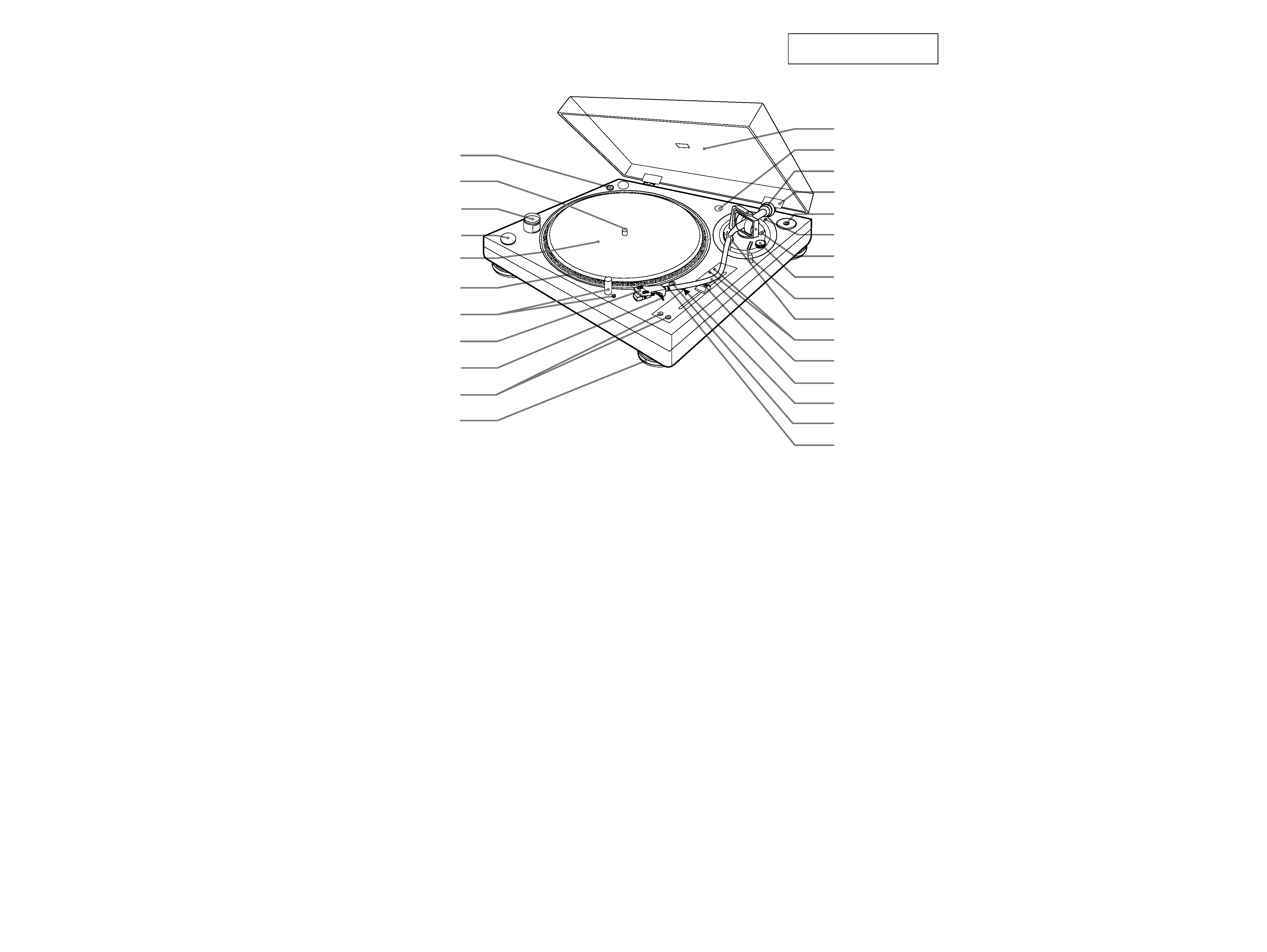
SECTION 1
GENERAL
1 POWER ON/OFF switch
2 Spindle
3 Strobo lamp
4 START/STOP button
5 Slip mat
6 Platter
7 TARGET LIGHT and release button
The TARGET LIGHT allows you to see the
position of the stylus in the dark. Push and
depress the TARGET LIGHT to turn it off.
Push the release button to raise the light again
and turn it on.
8 Cartridge and headshell
9 Finger lift
q; PITCH BEND + and buttons
qa Insulator
qs Dust cover
qd Headshell holder
qf Counter weight
qg Hinge
qh 45 adaptor
qj height adj (adjusting) lever
Use this lever to adjust the vertical position of the
tonearm (wd).
qk LOCK lever (for height adjustment)
ql ANTI-SKATING dial
w; Cueing lever
wa Arm stand
ws Speed-adjustment hole
This hole is for use by qualified service
technicians only.
wd Tonearm
wf PITCH ADJ. (adjusting) knob
wg QUARTZ lock button
wh SPEED (33/45) button
wj Locking ring
1
qs
qd
qf
qg
qh
qj
qk
ql
w;
wa
ws
wd
wf
wg
wh
wj
2
3
4
5
6
7
8
9
0
qa
This section is extracted from
instruction manual.
4
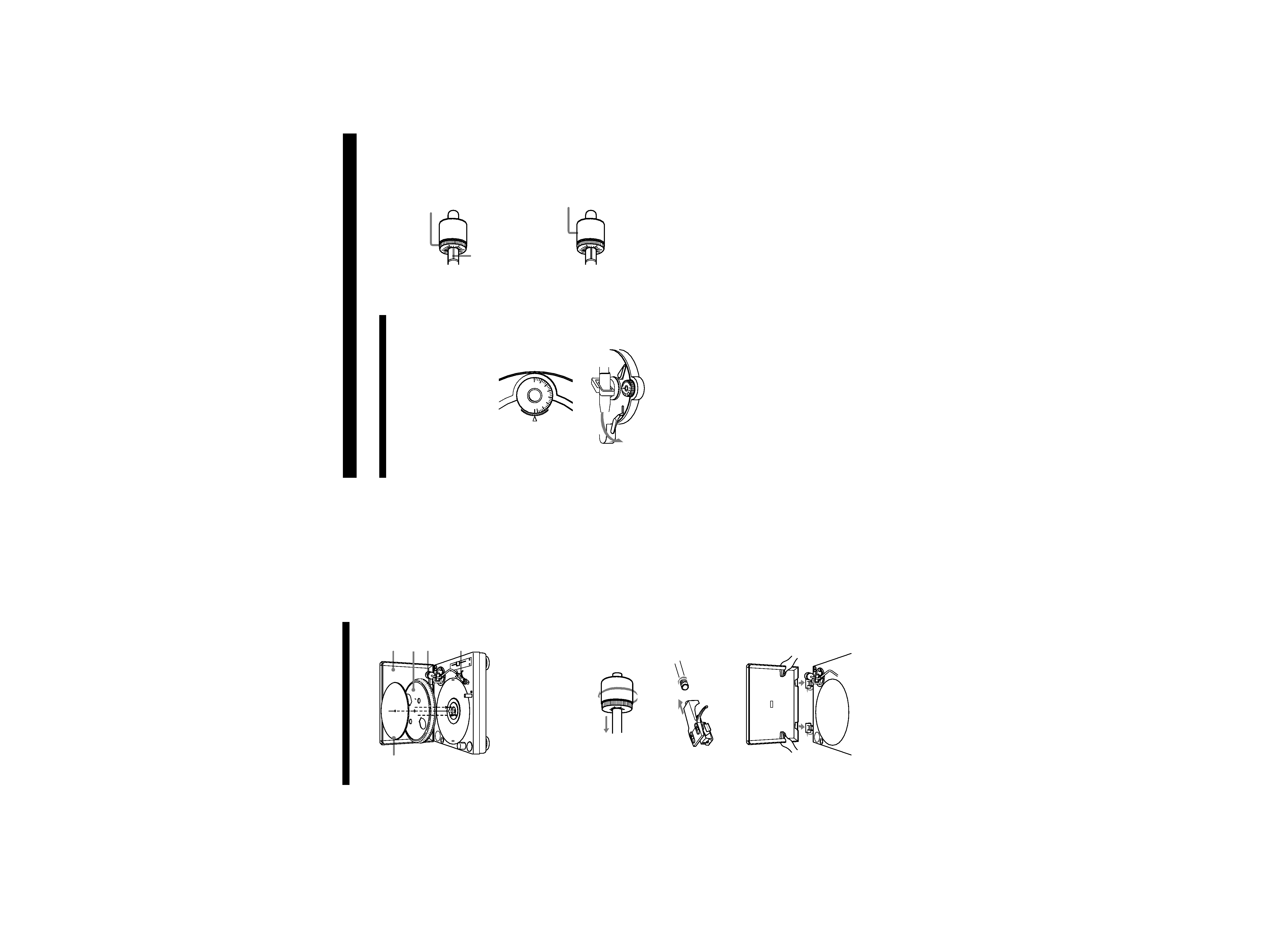
Assembling
the
Turntable
3
4
5
1
2
1
Carefully
place
the
platter
onto
the
spindle.
Make
sure
the
two
pins
on
the
bottom
of
the
platter
are
properly
inserted
into
the
two
holes
in
the
motor,
as
indicated
by
the
arrows
in
the
illustration
above.
2
Place
the
slip
mat
on
the
platter.
3
Slide
the
counterweight
onto
the
shaft
at
the
rear
of
the
tonearm
and
turn
3
or
4
times
in
the
direction
of
the
arrow.
4
Insert
the
headshell
into
the
end
of
the
tonearm.
Turn
the
locking
ring
in
the
direction
of
the
arrow
until
the
headshell
is
secure.
5
Insert
the
hinges
on
the
dust
cover
into
the
hinge
pockets
on
the
rear
of
the
cabinet.
6
Getting
Started
Adjusting
the
Turntable
Before
attempting
to
play
any
records,
be
sure
to
complete
the
following
steps
to
properly
adjust
the
tonearm
balance,
tracking
force
and
anti-skating
dial.
Failure
to
complete
these
adjustments
will
result
in
inferior
sound
quality
and
may
cause
permanent
damage
to
the
stylus
and
record.
1
Make
sure
the
turntable
is
level.
2
Set
ANTI-SKATING
to
"0.
"
0
1
2
3
4
5
6
7
AN
T
I-
S
K
A
T
IN
G
3
Set
the
cueing
lever
to
the
down
position.
4
Turn
up
the
protective
cover
to
expose
the
stylus,
and
move
the
tonearm
to
the
space
between
the
arm
stand
and
the
platter.
Take
care
not
to
damage
the
stylus.
5
Balance
the
tonearm
by
turning
the
counterweight
either
clockwise
or
counterclockwise.
When
the
tonearm
is
properly
balanced
It
will
remain
level
with
the
platter
when
released.
It
should
not
tilt
in
the
direction
of
either
the
headshell
or
the
counterweight.
6
Return
the
tonearm
to
the
arm
stand.
7
A
properly
balanced
tonearm
has
a
tracking
force
of
zero.
Therefore,
rotate
the
tracking
force
scale
ring
until
"0
"is
aligned
to
the
index
line.
Restrain
the
counterweight
with
your
other
hand
so
that
it
does
not
rotate
along
with
the
scale
ring.
0
Index
line
8
When
you
use
the
supplied
cartridge,
turn
the
counterweight
counterclockwise
one
full
rotation,
and
then
continue
turning
it
until
the
index
line
comes
to
1.
Since
one
full
rotation
of
the
counterweight
yields
a
tracking
force
of
3
grams,
this
adjustment
results
in
a
tracking
force
of
4
grams,
which
is
the
normal
requirement
for
the
supplied
cartridge.
You
can
set
a
tracking
force
of
3
to
7
grams.
1
When
optionally
available
cartridge
is
used
The
tracking
force
scale
ring
is
marked
in
0.1-gram
units.
One
full
rotation
yields
a
tracking
force
of
3
grams.
9
Set
ANTI-SKATING
to
the
same
value
as
the
tracking
force
scale
ring.
The
numbers
on
the
ANTI-SKATING
dial
indicate
the
number
of
grams
in
tracking
force.
Turn
this
ring
so
that
the
"0"
lines
up
with
the
index
line.
Turn
the
counterweight
counterclockwise
one
full
rotation,
and
then
a
little
more
until
the
index
line
is
aligned
to
1.
55
SECTION 2
DIAGRAMS
Note on Printed Wiring Board:
· X : parts extracted from the component side.
· Y : parts extracted from the conductor side.
· b : Pattern from the side which enables seeing.
Note on Schematic Diagram:
· All capacitors are in µF unless otherwise noted. pF: µµF
50 WV or less are not indicated except for electrolytics
and tantalums.
· All resistors are in
and 1/4 W or less unless otherwise
specified.
· C : panel designation.
· U : B+ Line.
· V : B Line.
· Voltages are dc with respect to ground under no-signal
conditions.
no mark : Power on
· Voltages are taken with a VOM (Input impedance 10 M
).
Voltage variations may be noted due to normal produc-
tion tolerances.
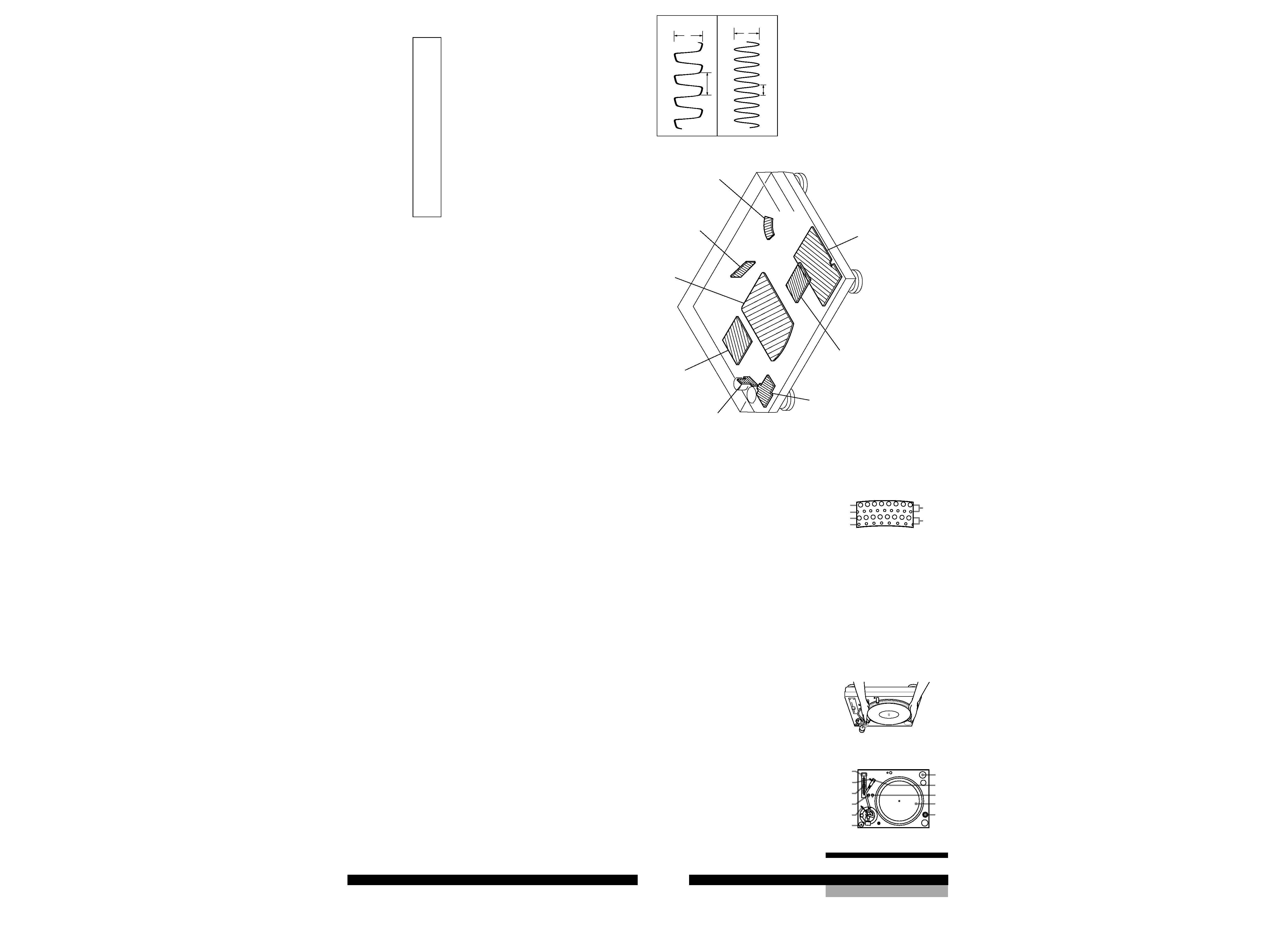
2-1. Circuit Boards Location
Note: The components identified by mark 0 or dotted line
with mark 0 are critical for safety.
Replace only with part number specified.
NOTE FOR PRINTED WIRING BOARD AND SCHEMATIC DIAGRAM
7
Operations
Operations
5
Remove
the
protective
cover
from
the
cartridge
and
release
the
arm
stopper.
6
Set
the
cueing
lever
in
the
up
position.
Move
the
tonearm
to
the
desired
point
on
the
record.
7
Set
the
cueing
lever
to
the
down
position.
The
tonearm
will
descend
slowly
to
the
record
and
play
will
begin.
8
If
you
want
to
change
the
pitch,
press
the
QUARTZ
lock
button
(the
QUARTZ
indicator
will
turn
off).
Then
adjust
the
pitch
by
moving
the
PITCH
ADJ.
knob.
The
distance
from
the
center
position
to
the
farthest
point
on
the
scale
represents
a
change
of
10%
in
the
pitch.
You
can
also
use
the
PITCH
BEND
+
and
buttons
to
change
the
pitch
(see
"Using
the
PITCH
BEND
+
and
buttons"
on
page
8).
9
If
you
wish,
you
can
return
to
normal
speed
(33
1/3
or
45
rpm)
while
the
PITCH
ADJ.
knob
is
off
center
by
pressing
the
QUARTZ
lock
button
(the
QUARTZ
indicator
will
turn
on).
Press
the
QUARTZ
lock
button
again
to
go
back
to
the
previous
pitch
setting
(the
QUARTZ
indicator
will
turn
off).
Note
The
PITCH
ADJ.
knob
does
not
function
while
the
QUARTZ
lock
is
on
(i.e.,
while
the
QUARTZ
indicator
is
on).
10
To
adjust
the
volume,
use
the
respective
channel
fader
on
the
mixer,
or
the
volume
control
on
the
stereo
component
system
or
amplifier.
To
stop
play
1
Set
the
cueing
lever
in
the
up
position
and
return
the
tonearm
to
the
arm
stand.
Attach
the
protective
cover
onto
the
cartridge
to
prevent
damage
to
the
stylus.
2
Press
Bx
START/STOP.
The
platter
stops
rotating.
Secure
the
tonearm
with
the
arm
stopper.
3
Turn
POWER
to
OFF.
To
pause
play
Press
Bx
START/STOP
or
set
the
cueing
lever
in
the
up
position
to
raise
the
stylus.
Playing
a
Record
5
8
6
3,8,9
5
8,9
6,7
1
4
2
3
Before
playing
a
record,
be
sure
the
PHONO/LINE
switch
on
the
mixer
is
set
to
PHONO.
1
Place
a
record
on
the
platter.
Note
Place
only
one
record
on
the
platter
at
a
time.
If
two
or
more
records
are
stacked
on
the
platter,
the
stylus
will
not
make
proper
contact
with
the
grooves
and
the
quality
of
reproduction
will
be
impaired.
2
Turn
the
POWER
switch
to
ON.
The
strobo
lamp,
the
QUARTZ
lock
indicator,
and
SPEED
indicator
light
up.
Turn
the
POWER
switch
on
the
mixer
and
amplifier
to
ON
also.
3
Set
PITCH
ADJ.
knob
to
the
center
position.
When
the
turntable
is
turned
on,
the
platter
speed
is
automatically
set
to
33
rpm.
Verify
that
the
green
indicator
lights
up.
4
Press
Bx
START/STOP.
The
platter
starts
rotating.
If
you
select
33
rpm
when
the
turntable
is
connected
to
a
50
Hz
power
source,
the
uppermost
row
of
the
strobe
dots
should
appear
to
stand
still.
33
45
45
33
50
Hz
60
Hz
(Continued)
8
Operations
To
play
an
another
part
of
the
record
1
Set
the
cueing
lever
to
the
up
position
to
raise
the
stylus.
2
Move
the
tonearm
to
the
desired
position.
3
Set
the
cueing
lever
to
the
down
position.
To
play
a
45
single
Place
the
supplied
45
adaptor
onto
the
spindle.
Press
SPEED
to
select
45
rpm.
The
green
indicator
changes
to
red.
After
you
have
finished
using
the
adaptor,
return
it
to
the
adaptor
tray.
Using
the
PITCH
BEND
+
and
buttons
You
can
use
the
PITCH
BEND
+
and
buttons
to
synchronize
the
beat
of
the
selection
playing
on
one
turntable
with
the
beat
of
another
selection
playing
on
the
other
turntable.
You
can
use
these
buttons
even
if
the
QUARTZ
lock
button
is
turned
on
or
off.
1
Use
the
PITCH
ADJ.
knob
to
synchronize
the
speed
of
the
selection
playing
on
one
of
the
turntables
with
the
speed
of
the
selection
on
the
other
turntable.
2
Press
the
PITCH
BEND
+
and
buttons
to
synchronize
the
beat
of
both
selections.
Pressing
and
holding
down
the
+
or
button
causes
the
selection
to
play
10%
faster
or
slower
than
the
normal
playing
speed.
z
If
the
strobe
dots
are
not
stationary
when
the
PITCH
ADJ.
knob
is
set
to
the
center
position
Adjust
the
platter
speed
by
sliding
the
PITCH
ADJ.
knob
toward
+
or
until
the
strobe
dots
become
stationary.
z
If
you
have
an
extra
headshell,
keep
it
in
the
headshell
holder.
POWER board
TONE ARM board
MAIN board
LED SW board
PAUSE/START board
LED board
RELAY board
MOTOR board
1 IC7 0
2 IC10 2 (XOUT)
3.5Vp-p
5Vp-p
180msec
250msec
· WAVEFORMS
MAIN SECTION