1
CD
Model Name Using Similar Mechanism CFD-S47
Section
CD Loading Mechanism Type
FLM-DR45-149
CD Mechanism Type
KSM-213CCP
Optical Pick-up Name
KSS-213C
Tape
Model Name Using Similar Mechanism NEW
Section Tape Transport Mechanism Type
MF-DR45
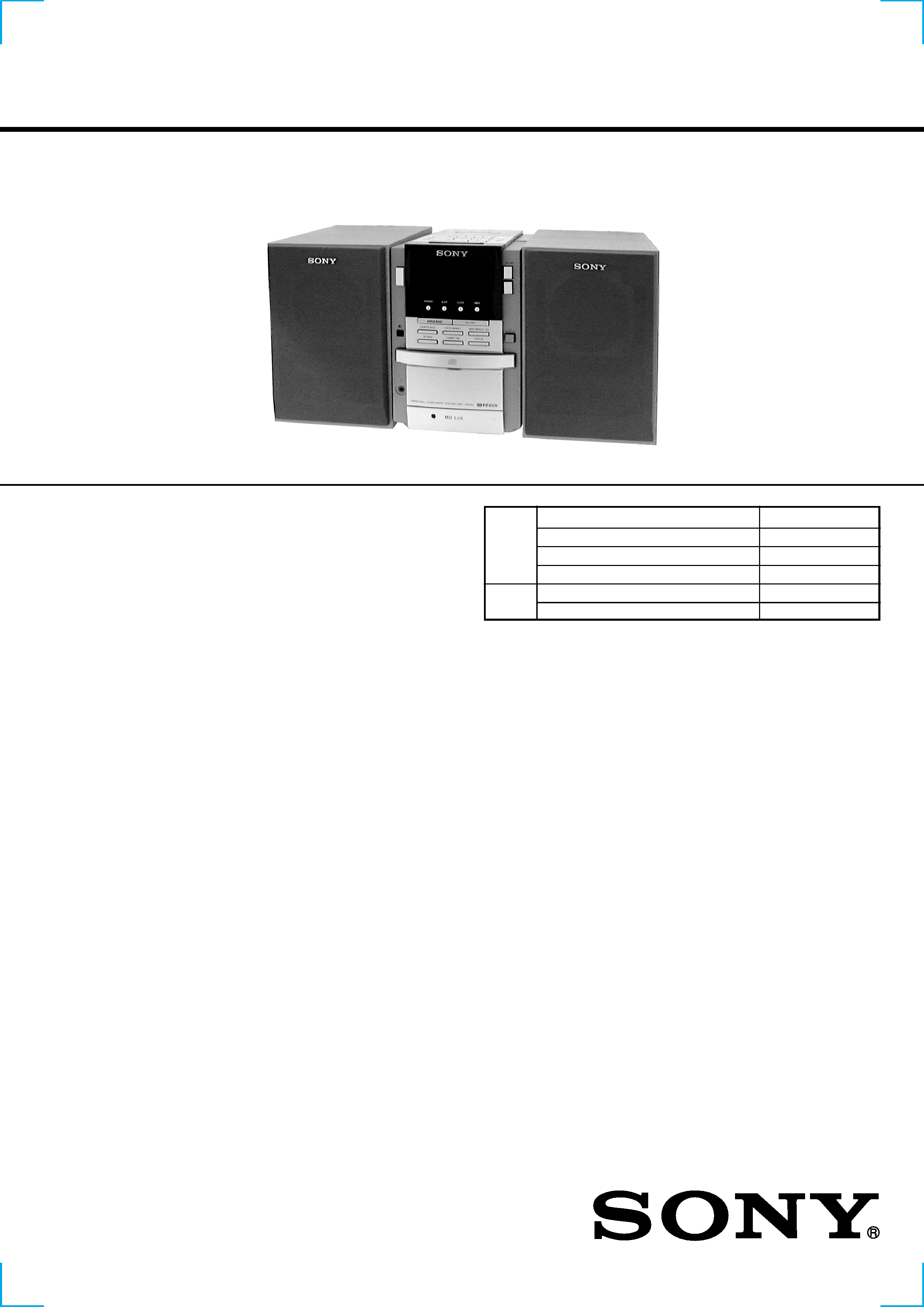
SERVICE MANUAL
US Model
Canadian Model
PMC-DR45
PERSONAL COMPONENT SYSTEM
CD player section
System
Compact disc digital audio system
Laser diode properties
Material: GaAlAs
Wave length: 780 nm
Emission duration: Continuous
Laser output: Less than 44.6 µW
(This output is the value measured at a distance of
about 200 mm from the objective lens surface on
the optical pick-up block with 7 mm aperture.)
Spindle speed
200 r/min (rpm) to 500 r/min (rpm) (CLV)
Number of channels
2
Frequency response
20 - 20,000 Hz +0/1 dB
Wow and flutter
Below measurable limit
Radio section
Frequency range
FM: 87.6 - 108 MHz
AM: 530 - 1,710 kHz
Antennas
FM: Lead antenna
AM: Loop antenna
Continued on next page
Cassette-corder section
Recording system
4-track 2-channel stereo
Fast winding time
Approx. 120 s (sec.) with Sony cassette C-60
Frequency response
TYPE I (normal): 50 - 14,000 Hz
General
Speaker
Full range: 8 cm (3 1/4 in.) dia., 4 ohms,
cone type
× 2
Input
LINE IN jack (stereo minijack)
Minimum input level 440 mV
Outputs
Headphones jack (stereo minijack)
For 16 - 64 ohms impedance headphones
LINE OUT jack (stereo minijack)
Rated output level 330 mV at load impedance
47 kilohms
OPTICAL DIGITAL OUT (CD) (optical output connector)
Wave length: 760 - 880 nm
Power output (excluding US model)
15 W + 15 W (at 4 ohms, 10% harmonic distortion
in AC operation)
SPECIFICATIONS
AUDIO POWER SPECIFICATIONS
POWER OUTPUT AND TOTAL
HARMONIC DISTORTION
With 4-ohm loads, both channels driven from
150 - 10,000 Hz; rated 13 W per channel-
minimum RMS power, with no more than 10%
total harmonic distortion in AC operation.

2
Power requirements
For personal component system:
120 V AC, 60 Hz
For remote control:
3 V DC, 2 AA (size R6) batteries
Power consumption
AC 45 W (US model)
AC 50W (Canadian model)
Dimensions (incl. projecting parts)
Player: approx. 137
× 202 × 212 mm (w/h/d)
(5 1/2
× 8 × 8 3/8 inches)
Left speaker: approx. 137
× 202 × 212 mm
(w/h/d) (5 1/2
× 8 × 8 3/8 inches)
Right speaker: approx. 137
× 202 × 180 mm
(w/h/d) (5 1/2
× 8 × 7 1/8 inches)
Mass
Player: approx. 1.8 kg (3 lb. 15 oz.)
Left speaker: approx. 3 kg (6 lb. 10 oz.)
Right speaker: approx. 1.5 kg (3 lb. 5 oz.)
Supplied accessories
Remote control (1) (RMT-CDR45A)
FM lead antenna (1)
AM loop antenna (1)
Audio connecting cord (1)
Design and specifications are subject to change without
notice.
TABLE OF CONTENTS
1. SERVICING NOTES ......................................................... 3
2. GENERAL
Playing a CD ........................................................................... 4
Listening to the radio ............................................................... 4
Playing a tape .......................................................................... 5
Recording on a tape ................................................................. 5
Setting the clock ...................................................................... 6
3. DISASSEMBLY
3-1. Cabinet (Front) Assy ........................................................... 7
3-2. Cabinet (Rear) ..................................................................... 8
3-3. Front Board ......................................................................... 8
3-4. Control Board ...................................................................... 9
3-5. Line Board ........................................................................... 9
3-6. Tuner Board ....................................................................... 10
3-7. Holder, Cassette ................................................................ 10
3-8. Top Block Assy ................................................................. 11
3-9. CD Assy, H/P Board .......................................................... 11
3-10. Main Board ....................................................................... 12
3-11. Tape Mechanism Block ..................................................... 12
3-12. Top Board .......................................................................... 13
3-13. "Plate Assy, Chuck", Tray ................................................. 13
3-14. Loading Board ................................................................... 14
3-15. CD Board .......................................................................... 14
3-16. CD Mechanism Block ....................................................... 15
3-17. Power Board ...................................................................... 15
4. MECHANICAL ADJUSTMENTS ............................... 16
5. ELECTRICAL ADJUSTMENTS
5-1. Tape Section ...................................................................... 16
5-2. Tuner Section .................................................................... 18
5-3. CD Section ........................................................................ 20
6. DIAGRAMS
6-1. IC Pin Descriptions ........................................................... 21
6-2. Circuit Boards Location .................................................... 23
6-3. Block Diagram Tuner Section ....................................... 25
6-4. Block Diagram CD Section ........................................... 27
6-5. Block Diagram Tape Section ........................................ 29
6-6. Block Diagram System Control, Power Section ........... 31
6-7. Printed Wiring Board Tuner Section ............................. 33
6-8. Schematic Diagram Tuner Section ................................ 35
6-9. Printed Wiring Boards CD Section ............................... 37
6-10. Schematic Diagram CD Section .................................... 39
6-11. Printed Wiring Board TC Section ................................. 41
6-12. Schematic Diagram TC Section .................................... 43
6-13. Printed Wiring Board Main Section .............................. 45
6-14. Schematic Diagram Main Section ................................. 47
6-15. Printed Wiring Board Control Section .......................... 49
6-16. Schematic Diagram Control Section ............................. 53
6-17. Printed Wiring Board Front Section .............................. 55
6-18. Schematic Diagram Front Section ................................ 56
6-19. Printed Wiring Board Top Section ................................ 57
6-20. Schematic Diagram Top Section ................................... 58
6-21. Printed Wiring Board Line Section ............................... 59
6-22. Schematic Diagram Line Section .................................. 59
6-23. Printed Wiring Boards Power Section ........................... 61
6-24. Schematic Diagram Power Section ............................... 63
6-25. IC Block Diagrams ............................................................ 65
7. EXPLODED VIEWS
7-1. Cabinet Section ................................................................. 69
7-2. Cabinet (Top) Section ....................................................... 70
7-3. CD Chassis Section ........................................................... 71
7-4. Mechanism Deck Section (1) ............................................ 72
7-5. Mechanism Deck Section (2) ............................................ 73
7-6. Optical Pick-up Section .................................................... 74
7-7. Speaker (L) Section ........................................................... 75
7-8. Speaker (R) Section ........................................................... 76
8. ELECTRICAL PARTS LIST......................................... 77
3
This Compact Disc player is
classified as a CLASS 1
LASER product.
The CLASS 1 LASER
PRODUCT lable is located
on the bottom exterior.
SECTION 1
SERVICING NOTES
CAUTION
Use of controls or adjustments or performance of proce-
dures other than those specified herein may result in haz-
ardous radiation exposure.
Flexible Circuit Board Repairing
· Keep the temperature of the soldering iron around 270°C during
repairing.
· Do not touch the soldering iron on the same conductor of the
circuit board (within 3 times).
· Be careful not to apply force on the conductor when soldering
or unsoldering.
Notes on Chip Component Replacement
· Never reuse a disconnected chip component.
· Notice that the minus side of a tantalum capacitor may be dam-
aged by heat.
NOTES ON HANDLING THE OPTICAL PICK-UP BLOCK
OR BASE UNIT
The laser diode in the optical pick-up block may suffer electrostatic
breakdown because of the potential difference generated by the
charged electrostatic load, etc. on clothing and the human body.
During repair, pay attention to electrostatic breakdown and also use
the procedure in the printed matter which is included in the repair
parts.
The flexible board is easily damaged and should be handled with
care.
NOTES ON LASER DIODE EMISSION CHECK
The laser beam on this model is concentrated so as to be focused on
the disc reflective surface by the objective lens in the optical pick-
up block. Therefore, when checking the laser diode emission,
observe from more than 30 cm away from the objective lens.
SAFETY-RELATED COMPONENT WARNING!!
COMPONENTS IDENTIFIED BY MARK
0 OR DOTTED LINE
WITH MARK
0 ON THE SCHEMATIC DIAGRAMS AND IN
THE PARTS LIST ARE CRITICAL TO SAFE OPERATION.
REPLACE THESE COMPONENTS WITH SONY PARTS WHOSE
PART NUMBERS APPEAR AS SHOWN IN THIS MANUAL OR
IN SUPPLEMENTS PUBLISHED BY SONY.
ATTENTION AU COMPOSANT AYANT RAPPORT
À LA SÉCURITÉ!!
LES COMPOSANTS IDENTIFIÉS PAR UNE MARQUE
0 SUR LES
DIAGRAMMES SCHÉMATIQUES ET LA LISTE DES PIÈCES SONT
CRITIQUES POUR LA SÉCURITÉ DE FONCTIONNEMENT. NE
REMPLACER CES COMPOSANTS QUE PAR DES PIÈCES SONY
DONT LES NUMÉROS SONT DONNÉS DANS CE MANUEL OU
DANS LES SUPPLÉMENTS PUBLIÉS PAR SONY.
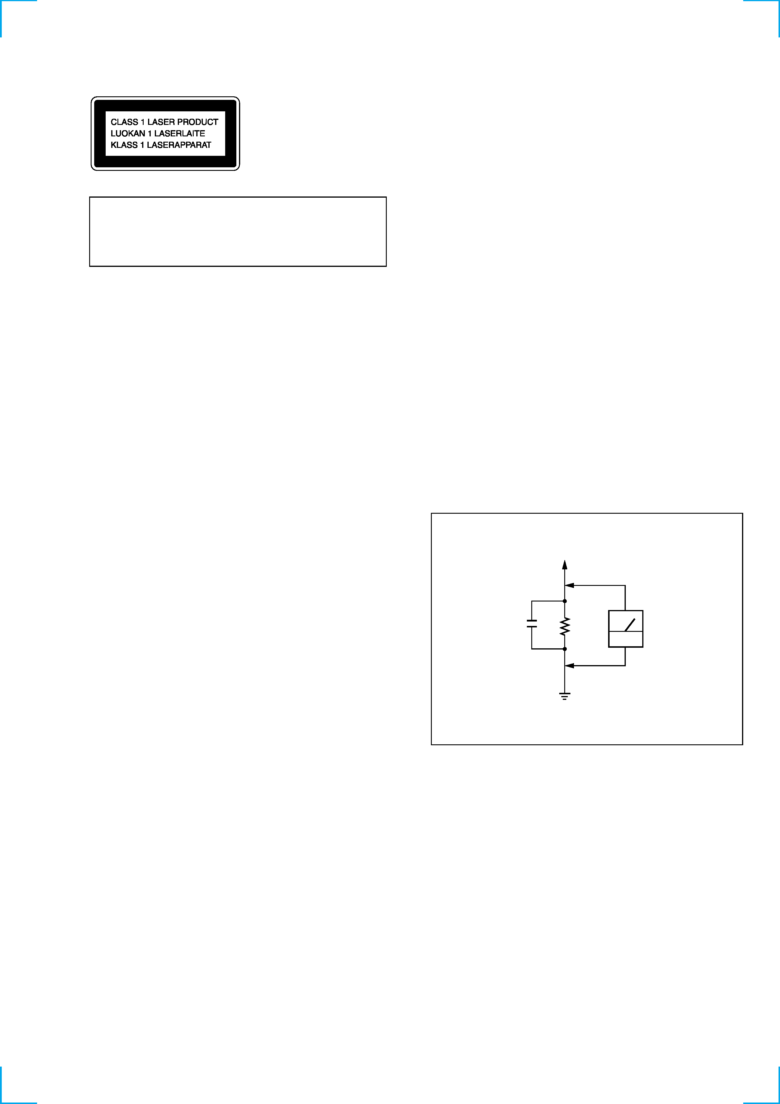
To Exposed Metal
Parts on Set
0.15µF
1.5k
AC
voltmeter
(0.75V)
Earth Ground
Fig. A. Using an AC voltmeter to check AC leakage.
SAFETY CHECK-OUT
After correcting the original service problem, perform the following
safety check before releasing the set to the customer:
Check the antenna terminals, metal trim, "metallized" knobs, screws,
and all other exposed metal parts for AC leakage. Check leakage as
described below.
LEAKAGE TEST
The AC leakage from any exposed metal part to earth ground and
from all exposed metal parts to any exposed metal part having a
return to chassis, must not exceed 0.5 mA (500 microamperes).
Leakage current can be measured by any one of three methods.
1. A commercial leakage tester, such as the Simpson 229 or RCA
WT-540A. Follow the manufacturers' instructions to use these
instruments.
2. A battery-operated AC milliammeter. The Data Precision 245
digital multimeter is suitable for this job.
3. Measuring the voltage drop across a resistor by means of a VOM
or battery-operated AC voltmeter. The "limit" indication is 0.75
V, so analog meters must have an accurate low-voltage scale. The
Simpson 250 and Sanwa SH-63Trd are examples of a passive
VOM that is suitable. Nearly all battery operated digital
multimeters that have a 2V AC range are suitable. (See Fig. A)
4
SECTION 2
GENERAL
This section is extracted
from instruction manual.
Basic Operations
4
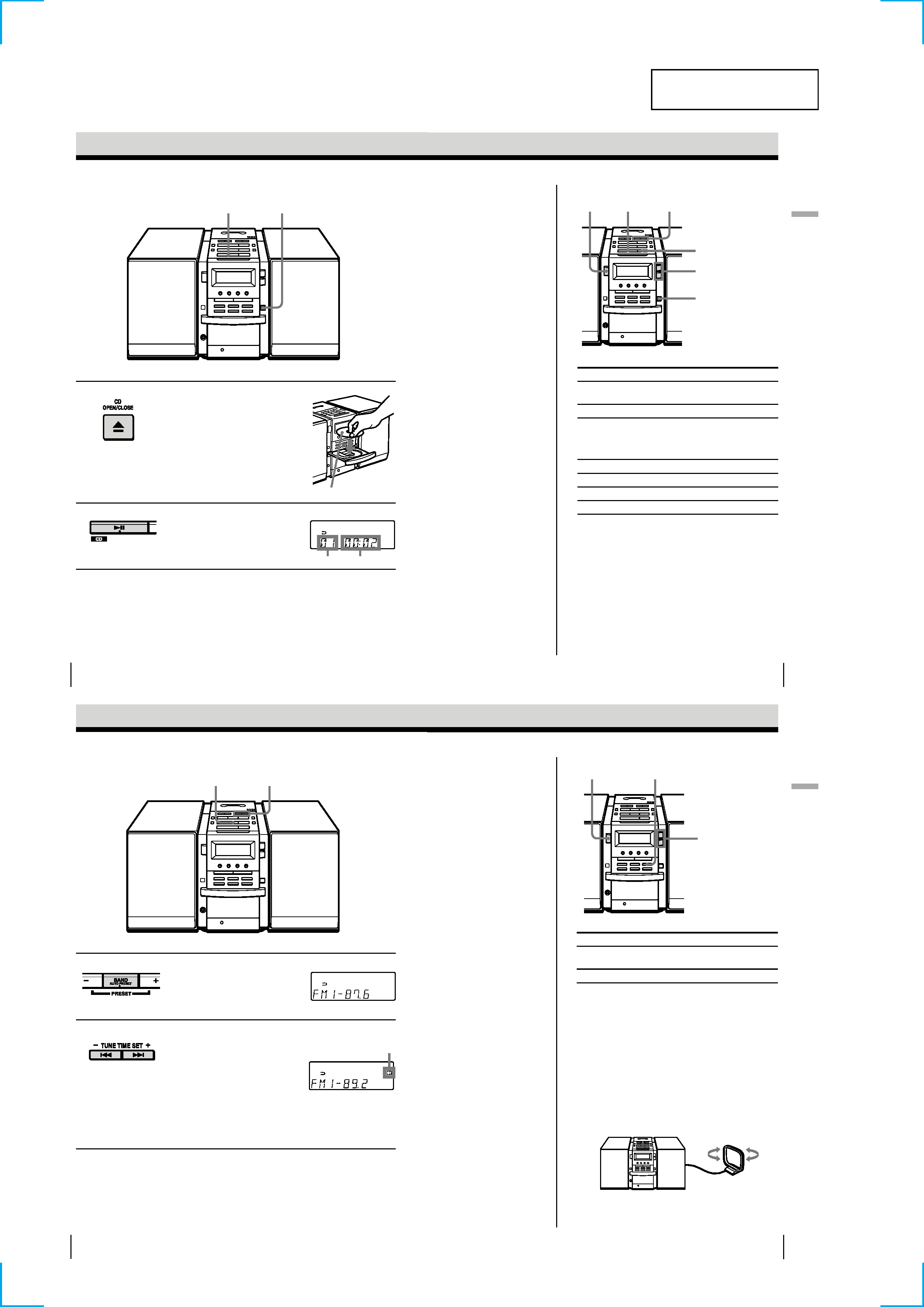
Playing a CD
Basic Operations
For hookup instructions, see pages 32 - 36.
1
Press Z CD OPEN/CLOSE
(direct power-on) and place the
CD on the CD tray.
2
Press u
.
(On the remote, press N on the
CD section.)
The CD tray closes and the player
plays all the tracks once.
With the label side up
Display
Playing time
Track number
21
Basic Operations
Basic
Operations
5
Use these buttons for additional operations
Tip
Next time you want to
listen to a CD, just press
u. The player turns on
automatically and starts
playing the CD.
To
Press
adjust the volume
VOLUME +,
(VOL +, on the remote)
stop playback
x
pause playback
u
(X on the remote)
Press again to resume play
after pause.
go to the next track
>
go back to the previous track
.
remove the CD
Z CD OPEN/CLOSE
turn on/off the player
POWER
u
.
, >
Z CD
OPEN/CLOSE
VOLUME +,
POWER
x
Basic Operations
6
Listening to the radio
For hookup instructions, see pages 32 - 36.
1
Press BAND·AUTO PRESET
until the band you want appears
in the display (direct power-on).
2
Hold down TUNE TIME SET + or
(TUNE + or on the remote)
until the frequency digits begin to
change in the display.
The player automatically scans
the radio frequencies and stops
when it finds a clear station.
If you cannot tune in a station,
press the button repeatedly to
change the frequency step by
step.
Display
2
1
Indicates an FM
stereo broadcast.
Basic Operations
Basic
Operations
7
Use these buttons for additional operations
Tips
· The "FM1" and "FM2"
bands have the same
functions.
You can store
the stations you want
separately in "FM1" and
"FM2".
· If the FM broadcast is
noisy, press MODE until
"MONO" appears in the
display and the radio
will play in monaural.
· Next time you want to
listen to the radio, just
press the BAND·AUTO
PRESET button. The
player turns on
automatically and starts
playing the previous
station.
To
Press
adjust the volume
VOLUME +,
(VOL +, on the remote)
turn on/off the radio
POWER
To improve broadcast reception
FM:
Keep the FM lead antenna as horizontal as possible
and reorient it.
If the FM broadcast is still noisy, disconnect the FM
lead antenna and connect the FM outdoor antenna
(not supplied) (page 36).
AM:
Keep the AM loop antenna as far as possible from the
player and reorient it.
VOLUME +,
MODE
POWER
5
Basic Operations
8
Playing a tape
For hookup instructions, see pages 32 - 36.
1
Press Z PUSH OPEN/CLOSE to
open the tape compartment
and
insert a recorded tape. Use TYPE I
(normal), TYPE II (high position)
and TYPE IV (metal) tapes.
2
Press Z PUSH OPEN/CLOSE to
close the compartment.
3
Press N.
(On the remote, press TAPE N.)
The player turns on (direct
power-on) and starts playing.
Display
1, 2
3
With the side you want
to play facing up
Tape counter
Basic Operations
Basic
Operations
9
Use these buttons for additional operations
To
Press
adjust the volume
VOLUME +,
(VOL +, on the remote)
stop playback
x
play the reverse side
n
fast-forward or rewind the tape
TAPE M or m
eject the cassette
Z PUSH OPEN/CLOSE
turn on/off the player
POWER
To select the direction mode of the tape
Press DIR MODE repeatedly.
To play
Display shows
one side of the tape
both sides of the tape
from the upper side to reverse
side only
both sides of the tape repeatedly
Tips
· Press COUNTER RESET
to reset the counter to
"000".
· Next time you want to
listen to a tape, just
press N or n. The
player turns on
automatically and starts
playing the tape.
DIR MODE
n
x
VOLUME +,
TAPE m
, M
COUNTER RESET
POWER
Z PUSH OPEN/CLOSE
Basic Operations
10
Recording on a tape
For hookup instructions, see pages 32 - 36. To record on a
MiniDisc or DAT recorder, connect the component (see
page 38).
1
Press Z PUSH OPEN/CLOSE to
open the tape compartment,
and
insert a blank tape. Use TYPE I
(normal) tape only.
Press Z PUSH OPEN/CLOSE
again to close the compartment.
2
Select the program source you
want to record.
To record from the CD player:
Insert a CD (see page 4) and press
x on the CD section.
To record from the radio:
Tune in the station you want (see
page 6).
3
1
With the side you want
to record on facing up
Display
3
3
Basic Operations
Basic
Operations
11
continued
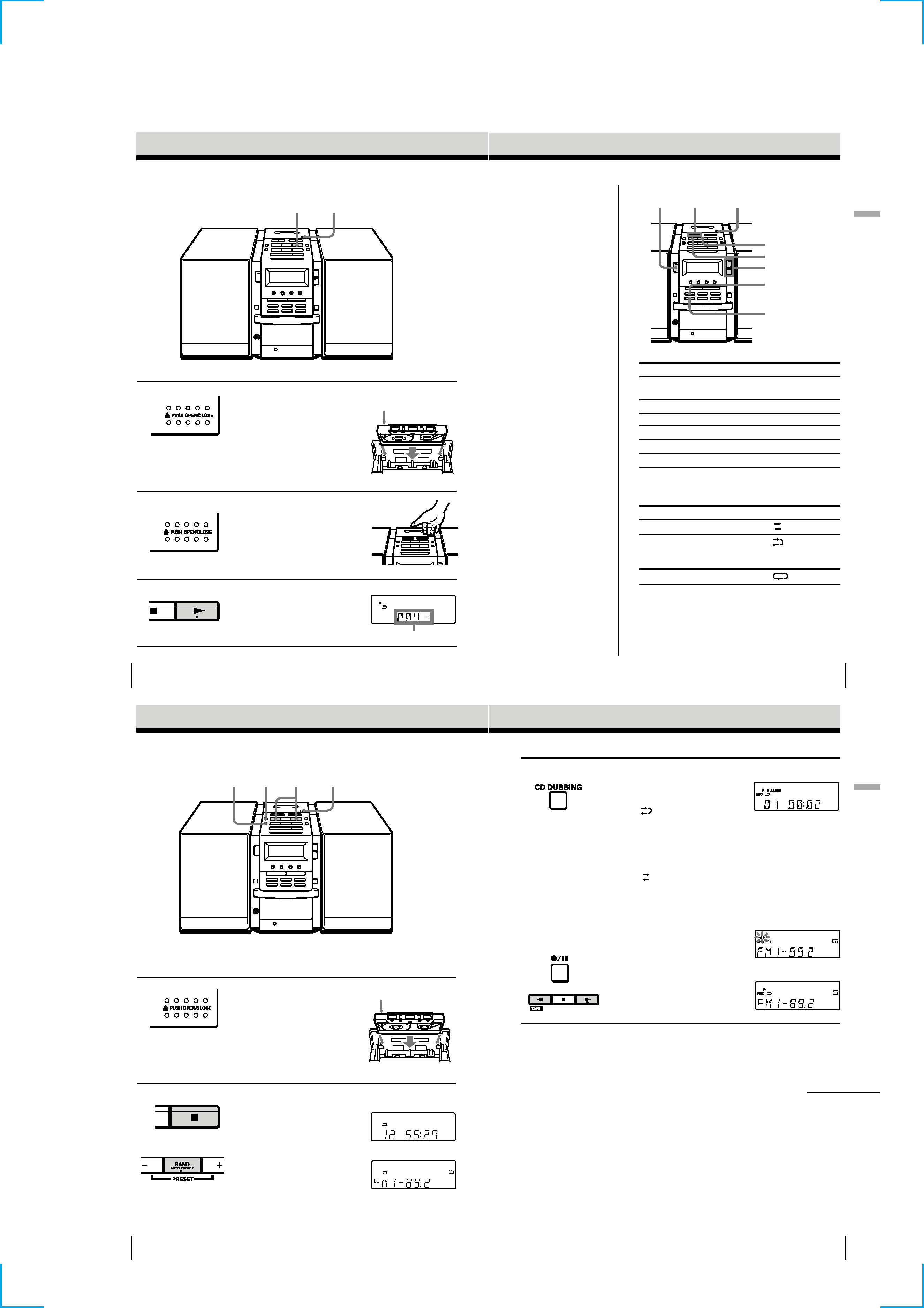
3
Start recording.
To record the whole CD
Press CD DUBBING.
When
is displayed:
If the tape is reversed with the
recording of the track unfinished,
the player will record the track
again from its beginning on the
reverse side.
When
is displayed:
If the tape reaches to its end, the
player stops.
To record the radio
(You can also record the CD
according to the following
procedure. Play the CD after
the
tape starts recording.)
Press z/X and then N.
To record on the reverse side,
press n.
(On the remote, while keeping
z/X pressed, press TAPE N or
n.)
m