1
SERVICE MANUAL
AEP Model
PMC-D407L
PERSONAL COMPONENT SYSTEM
CD player section
System
Compact disc digital audio system
Laser diode properties
Material: GaAlAs
Wave length: 780 nm
Emission duration: Continuous
Laser output: Less than 44.6
µW
(This output is the value measured at a distance of
about 200 mm from the objective lens surface on
the optical pick-up block with 7 mm aperture.)
Spindle speed
200 r/min (rpm) to 500 r/min (rpm) (CLV)
Number of channels
2
Frequency response
20 - 20,000 Hz +1/2.5 dB
Wow and flutter
Below measurable limit
Radio section
Frequency range
FM
Except Italian model
87.6 - 107 MHz
Italian model
87.5 - 108 MHz
MW
531 - 1,602 kHz
LW
153 - 279 kHz
IF
FM: 10.7 MHz
MW/LW: 450 kHz
Aerials
FM: External aerial terminal
MW/LW: External aerial terminal
Continued on next page
Cassette-corder section
Recording system
4-track 2-channel stereo
Fast winding time
Approx. 130 s (sec.) with Sony cassette C-60
Frequency response
TYPE I (normal): 40 - 15,000 Hz
Super woofer
Speaker
Woofer: 10 cm (4 in.) dia., 4.0 ohms, cone type
Power output
30 W (at 100 Hz)
Power consumption
AC 30 W
Dimensions (incl. projecting parts)
Approx. 210
× 210 × 247 mm (w/h/d)
(8 3/8
× 8 3/8 × 9 3/4 inches)
Mass
Approx. 4.1 kg (9 lb. 1 oz.)
CD
Model Name Using Similar Mechanism PMC-D307L
Section
CD Mechanism Type
KSM-213CDM
Optical Pick-up Name
KSS-213C
Tape
Model Name Using Similar Mechanism PMC-D307L
Section Tape Transport Mechanism Type
MF-D307
SPECIFICATIONS
MICROFILM
Ver 1.0 1998. 09

2
SAFETY-RELATED COMPONENT WARNING!!
COMPONENTS IDENTIFIED BY MARK
! OR DOTTED LINE
WITH MARK
! ON THE SCHEMATIC DIAGRAMS AND IN
THE PARTS LIST ARE CRITICAL TO SAFE OPERATION.
REPLACE THESE COMPONENTS WITH SONY PARTS WHOSE
PART NUMBERS APPEAR AS SHOWN IN THIS MANUAL OR
IN SUPPLEMENTS PUBLISHED BY SONY.
General
Speaker
Full range: 8 cm (3 1/4 in.) dia., 6.0 ohms,
cone type
× 2
Input
LINE IN jack (stereo minijack)
Minimum input level 250 mV
Outputs
Headphones jack (stereo minijack)
For 16 - 68 ohms impedance headphones
LINE OUT jack (stereo minijack)
Rated output level 440 mV at load impedance
47 kilohms
Optical digital output (optical output connector)
Wave length: 630 - 690 nm
Maximum power output
10 W + 10 W
Power requirements
For personal component system:
230 V AC, 50 Hz
For remote commander:
3 V DC, 2 R6 (size AA) batteries
Power consumption
AC 35 W
Dimensions (incl. projecting parts)
Player: approx. 130
× 211 × 200 mm (w/h/d)
(5 1/8
× 8 3/8 × 7 7/8 inches)
Left speaker: approx. 130
× 210 × 235 mm
(w/h/d) (5 1/8
× 8 3/8 × 9 3/8 inches)
Right speaker: approx. 130
× 210 × 200 mm
(w/h/d) (5 1/8
× 8 3/8 × 7 7/8 inches)
Mass
Player: approx. 1.7 kg (3 lb. 12 oz.)
Left speaker: approx. 3.2 kg (7 lb. 1 oz.)
Right speaker: approx. 1.6 kg (3 lb. 9 oz.)
Supplied accessories
Remote commander RMT-C305AD (1)
FM lead aerial (1)
MW/LW loop aerial (1)
Audio connecting cord (2)
Design and specifications are subject to change without
notice.
TABLE OF CONTENTS
1. SERVICING NOTES ......................................................... 3
2. GENERAL
2-1. Location of Controls ........................................................... 4
3. DISASSEMBLY
3-1. Cabinet (Rear) Section ........................................................ 5
3-2. Case (Lower) Section .......................................................... 6
3-3. Tape Mechanism Deck, Line Board .................................... 6
3-4. Cabinet (CD) Section .......................................................... 7
3-5. CD, System Board ............................................................... 7
3-6. RDS Board, LCD Section ................................................... 8
3-7. Optical Pick-up Section ....................................................... 8
3-8. Rear Chassis (Speaker) Assy ............................................... 9
3-9. Power Amp, Terminal, Jack Board ...................................... 9
3-10. Power Board ...................................................................... 10
3-11. Rear Chassis (Woofer Speaker) Assy ................................ 10
3-12. S/Woofer Amp Board ........................................................ 11
3-13. Woofer Power Board ......................................................... 11
4. MECHANICAL ADJUSTMENTS ............................... 12
5. ELECTRICAL ADJUSTMENTS
Tape Section .......................................................................... 12
Tuner Section ......................................................................... 14
CD Section ............................................................................ 16
6. DIAGRAMS
6-1. IC Pin Description ............................................................. 20
6-2. Circuit Boards Location .................................................... 21
6-3. Block Diagram Tuner Section ....................................... 23
6-4. Block Diagram CD Section ........................................... 25
6-5. Block Diagram Tape Section ........................................ 27
6-6. Printed Wiring Board Tuner Section ............................. 29
6-7. Schematic Diagram Tuner Section ................................ 31
6-8. Printed Wiring Boards RDS Section ............................. 33
6-9. Schematic Diagram RDS Section ................................. 35
6-10. Printed Wiring Boards CD Section ............................... 37
6-11. Schematic Diagram CD Section .................................... 39
6-12. Printed Wiring Boards Main Section ............................ 42
6-13. Schematic Diagram Main Section ................................. 45
6-14. Printed Wiring Boards Control Section ......................... 48
6-15. Schematic Diagram Control Section ............................. 51
6-16. Printed Wiring Boards Woofer Speaker Section ........... 55
6-17. Schematic Diagram Woofer Speaker Section ............... 57
6-18. Printed Wiring Boards Power Amplifier Section .......... 59
6-19. Schematic Diagram Power Amplifier Section .............. 61
7. EXPLODED VIEWS
7-1. Case Section ...................................................................... 68
7-2. Cabinet (Front) Section ..................................................... 69
7-3. Cabinet (CD) Section ........................................................ 70
7-4. Optical Pick-up Section ..................................................... 71
7-5. Tape Mechanism Deck Section-1 ...................................... 72
7-6. Tape Mechanism Deck Section-2 ...................................... 73
7-7. Speaker (L) Section ........................................................... 74
7-8. Speaker (R) Section ........................................................... 75
7-9. Woofer Speaker Section .................................................... 76
8. ELECTRICAL PARTS LIST ........................................ 77
3
CAUTION
Use of controls or adjustments or performance of procedures
other than those specified herein may result in hazardous ra-
diation exposure.
NOTES ON HANDLING THE OPTICAL PICK-UP
BLOCK OR BASE UNIT
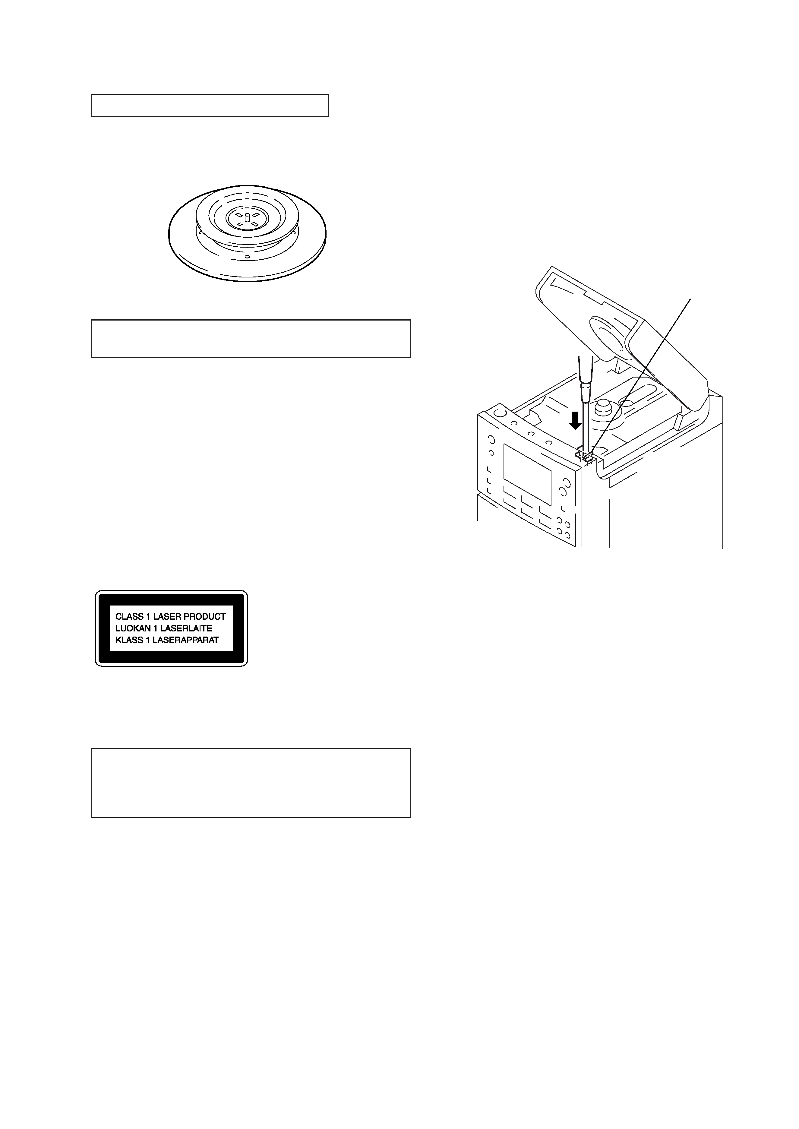
CHUCK PLATE JIG ON REPAIRING
On repairing CD section, playing a disc without the lid (CD), use
Chuck Plate Jig.
· Code number of Chuck Plate Jig: X-4918-255-1
The laser diode in the optical pick-up block may suffer electrostatic
breakdown because of the potential difference generated by the
charged electrostatic load, etc. on clothing and the human body.
During repair, pay attention to electrostatic breakdown and also use
the procedure in the printed matter which is included in the repair
parts.
The flexible board is easily damaged and should be handled with
care.
NOTES ON LASER DIODE EMISSION CHECK
The laser beam on this model is concentrated so as to be focused on
the disc reflective surface by the objective lens in the optical pick-
up block. Therefore, when checking the laser diode emission, ob-
serve from more than 30 cm away from the objective lens.
This Compact Disc player is classified as a
CLASS 1 LASER product.
The CLASS 1 LASER PRODUCT table is
location on the rear exterior.
SECTION 1
SERVICING NOTES
LASER DIODE AND FOCUS SEARCH OPERATION
CHECK
1. Turn OPERATE switch on with to disc inserted and press
FUNCTION button to CD position.
2. Open the lid (CD).
3. Turn on S801 as following figure.
4. Press the
( (CD) button.
5. Confirm the laser diode emission while observing the objecting
lens. When there is no emission, Auto Power Control circuit or
Optical Pick-up is broken.
Objective lens moves up and down three times for focus search.
S801
4
1
2
3
4
5
6
7
8
9
10
11
12
13
14
15
16
17
18
19
21
20
22
23
24
25
SECTION 2
GENERAL
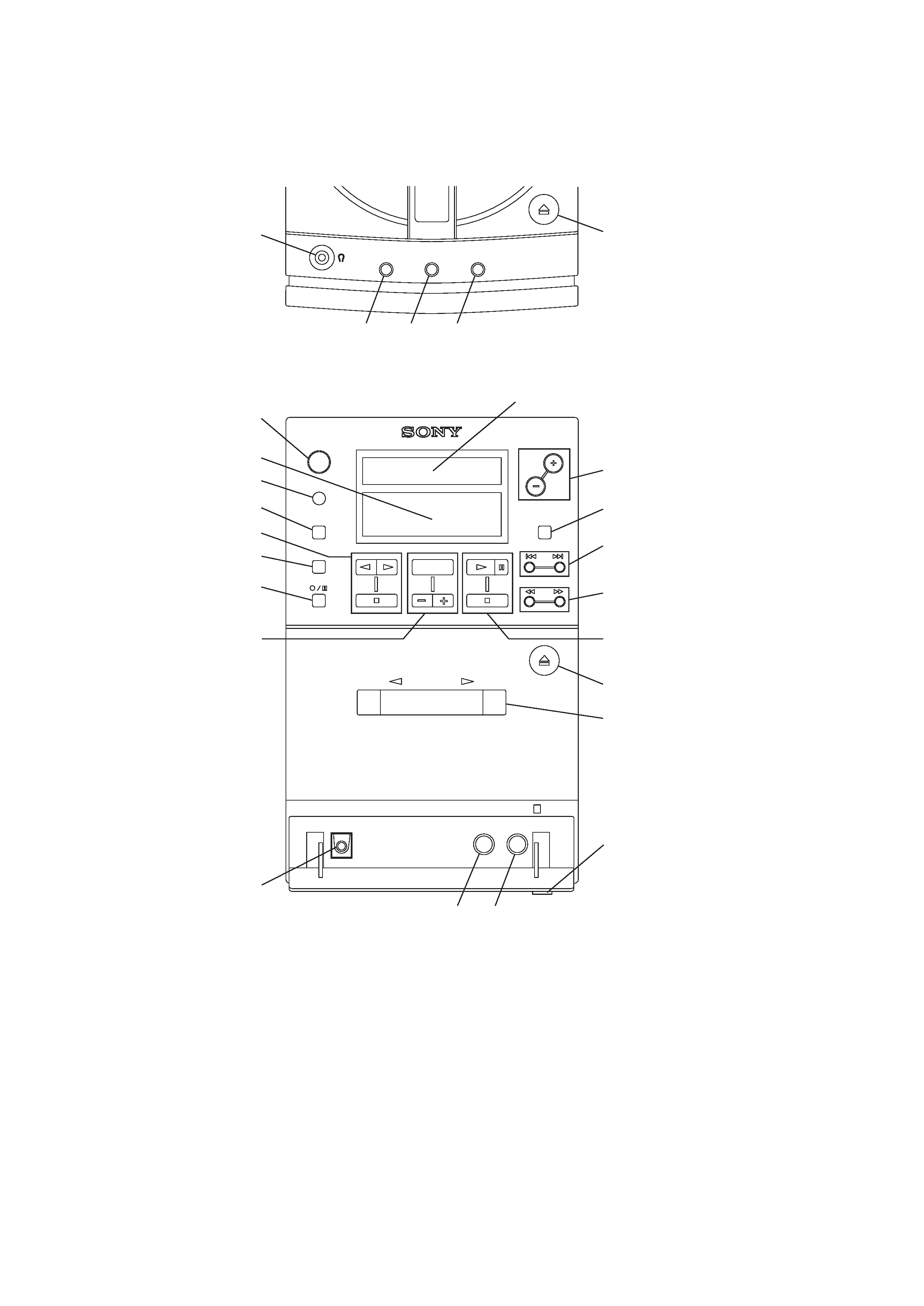
2-1. LOCATION OF CONTROLS
1.
6 PUSH OPEN/CLOSE button (CD)
2. PLAY MODE MONO/ST ISS button
3. PGM SET AUTO PRESET button
4. SOUND button
5.
2 (Headphones) jack
6. RDS display window
7. OPERATE (power) button
8. Display window
9. Remote sensor window
10. FUNCTION button
11. TAPE operation buttons
9 (Reverse side playback) button
( (Front side playback) button
p (Stop) button
12. DIR MODE button
13.
r/P (Recording/pause) button
14. RADIO operation buttons
BAND button
PRESET button
PRESET + button
15. OPTICAL DIGITAL OUT (CD) jack
16. VOLUME +/ button
17. DISPLAY ENTER/MEM button
18.
=/+, TUNE /+ button
19.
0/) button
20. CD operation buttons
( (Playback) button
P (Pause) button
p (Stop) button
21.
6 PUSH (cassette holder open) button
22. Cassette holder
23. OPEN
$ knob
24. LINE OUT jack
25. LINE IN jack
upper side view
front side view
5
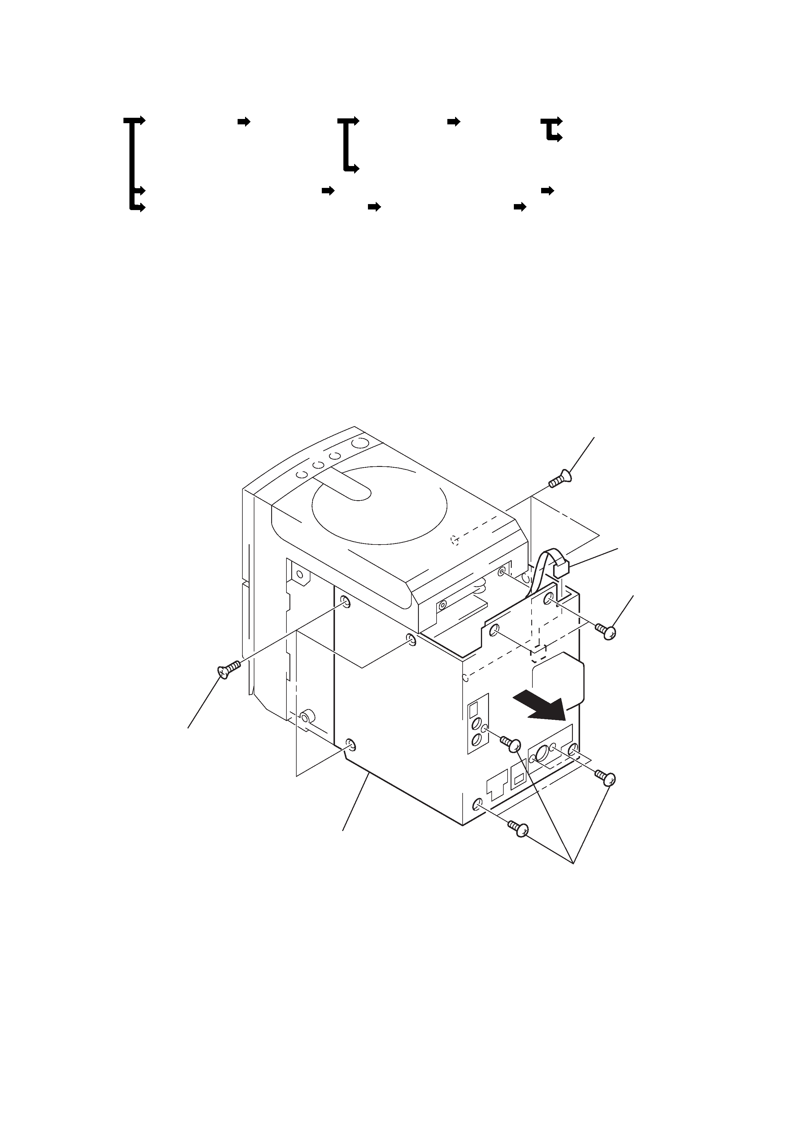
6 cabinet (rear) section
4 BVTP 3x10
3 BVTP 3x10
2 KTP 3x10
1 KTP 3x10
5 KH312
· The equipment can be removed using the following procedure.
SECTION 3
DISASSEMBLY
3-1. CABINET (REAR) SECTION
Set
Cabinet (rear)
Case (lower)
Cabinet (CD)
CD, System
RDS board, LCD section
section
section
section
board
Optical pick-up section
Tape mechanism deck, Line board
Rear chassis (speaker) assy
Power Amp, Terminal, Jack board
Power board
Rear chassis (woofer speaker) assy
S/Woofer Amp board
Woofer power board
Note : Follow the disassembly procedure in the numerical order given.