MICROFILM
SERVICE MANUAL
GLASSTRON
US Model
Canadian Model
Singapore Model
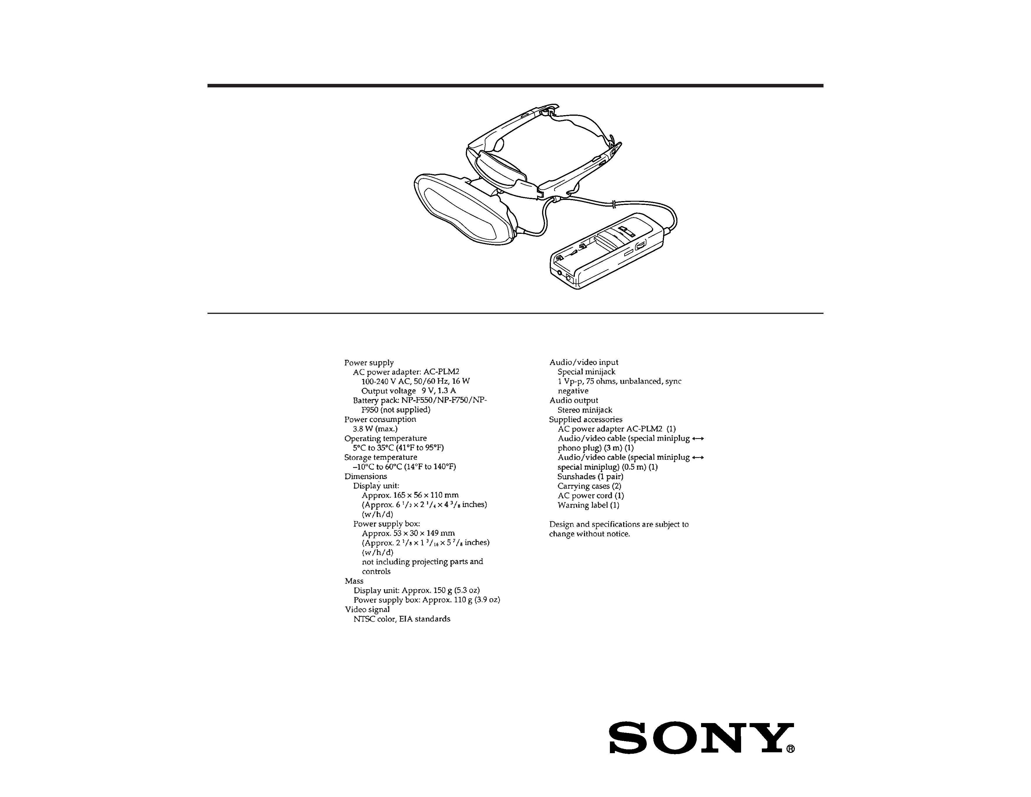
SPECIFICATIONS
PLM-A55
9-928-101-11

2
TABLE OF CONTENTS
1.
GENERAL
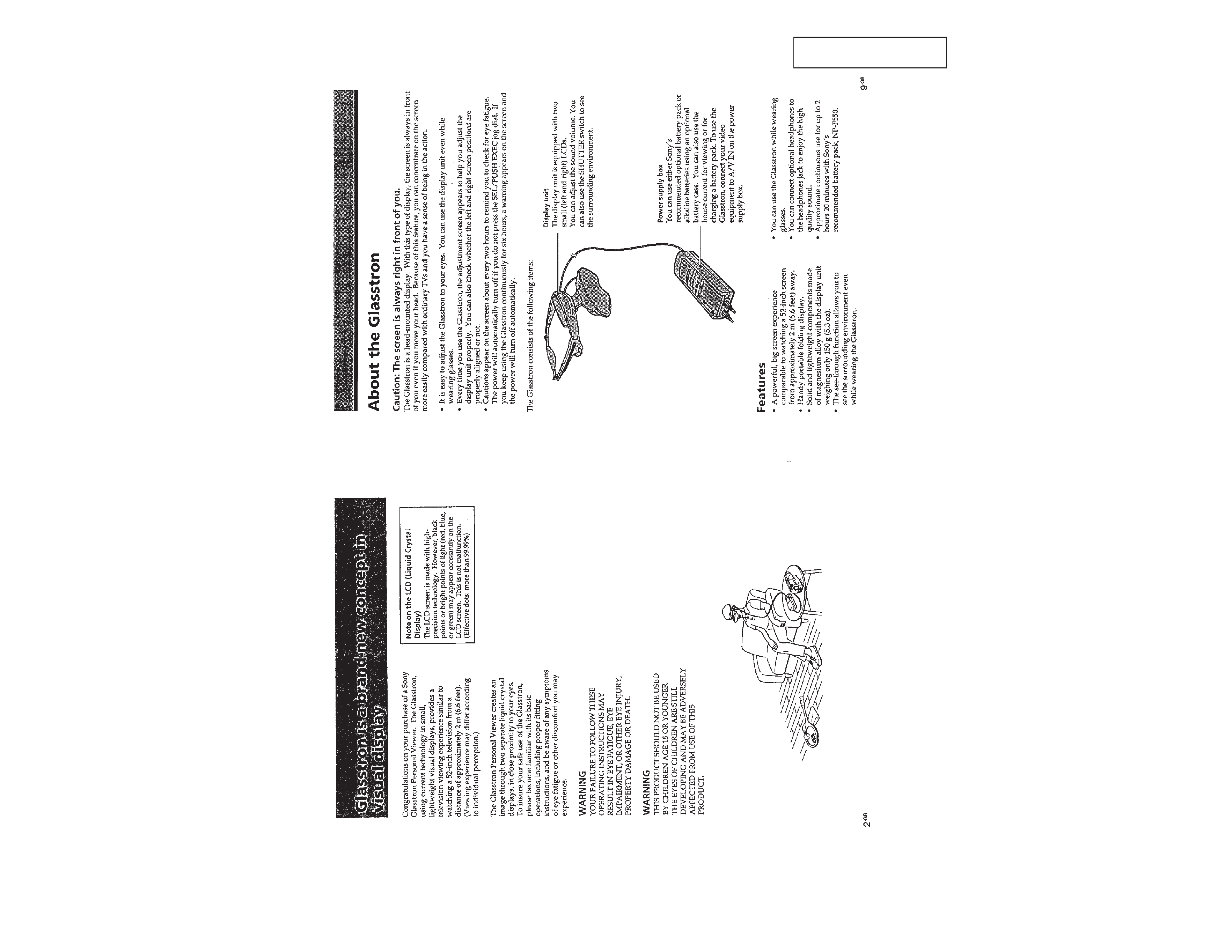
Glasstron is a brand-new concept in visual display .........
3
About the Glasstron ..........................................................
3
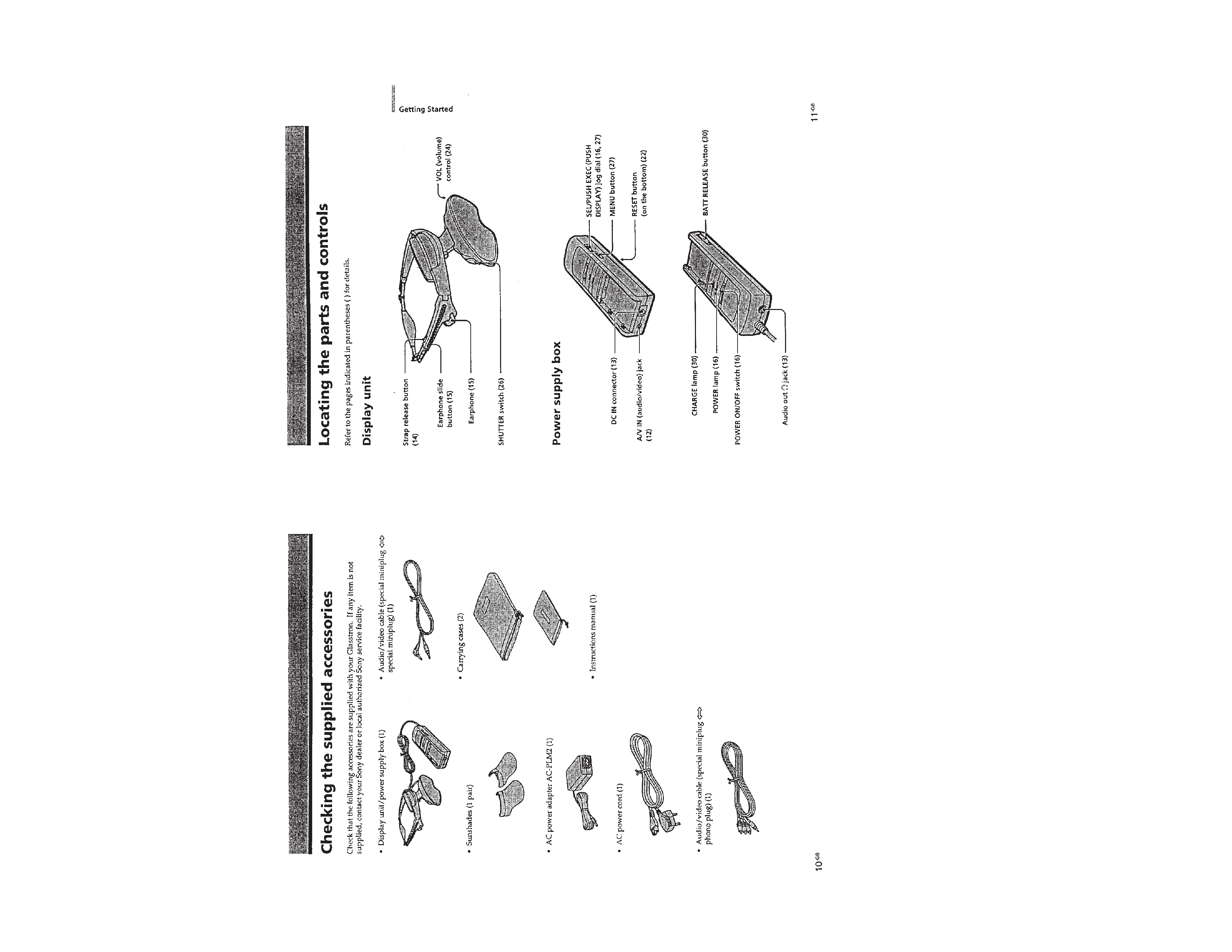
Checking the supplied accessories ...................................
4
Locating the parts and controls .........................................
4
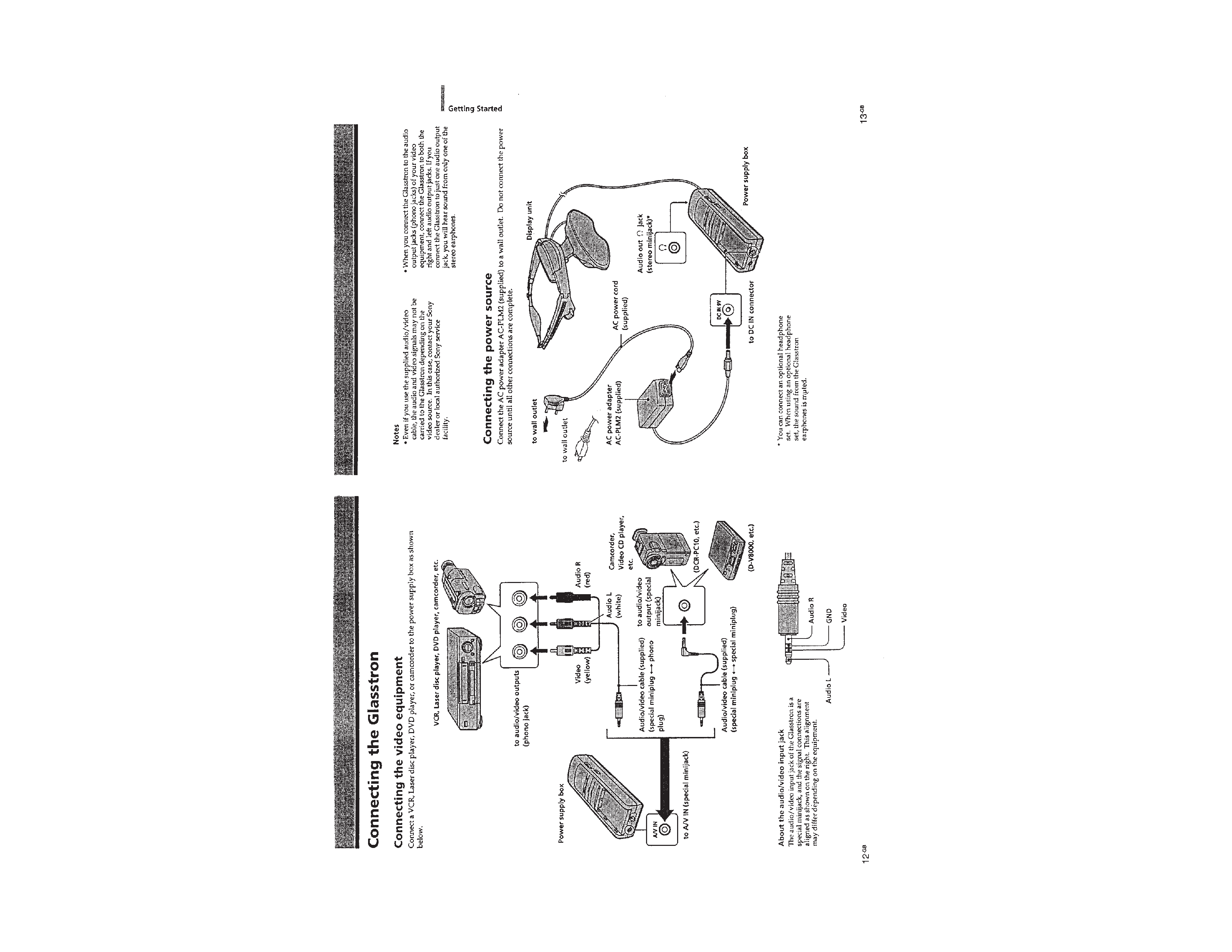
Connecting the Glasstron ..................................................
5
Wearing the Glasstron .......................................................
6
Turning on the Glasstron ..................................................
7
Setting the password .........................................................
9
Using the Glasstron ........................................................... 10
Viewing the surrounding environment
(See-through) .................................................................... 12
Adjusting the sound and picture ....................................... 12
Using with power sources other than
the AC adapter ................................................................... 14
2.
DISASSEMBLY ........................................................... 15
3.
ELECTRICAL ADJUSTMENTS ........................... 17
Power Supply Block ......................................................... 18
Video Block ....................................................................... 26
LCD Block ........................................................................ 27
4.
DIAGRAMS
4-1. IC Pin Function Description ............................................. 34
4-2. Block Diagram MAIN Section .................................. 41
4-3. Block Diagram AUDIO/KEY CONTROL Section ... 43
4-4. Block Diagram DISPLAY Section ............................ 45
4-5. Block Diagram POWER SUPPLY Section ............... 47
4-6. Printed Wiring Boards
YM-11 Board/SW-312 Board ..................................... 50
4-7. Schematic Diagram YM-11 Board (1/3) .................... 53
4-8. Schematic Diagram
YM-11 Board (2/3)/SW-312 Board ............................ 57
4-9. Schematic Diagram YM-11 Board (3/3) .................... 61
4-10. Schematic Diagram SA-52 Board .............................. 66
4-11. Printed Wiring Board SA-52 Board .......................... 69
4-12. Printed Wiring Board RG-46 Board .......................... 71
4-13. Schematic Diagram RG-46 Board ............................. 73
5.
EXPLODED VIEWS .................................................. 85
6.
ELECTRICAL PARTS LIST ................................. 88
Notes on chip component replacement
· Never reuse a disconnected chip component.
· Notice that the minus side of a tantalum capacitor may be dam-
aged by heat.
Flexible Circuit Board Repairing
· Keep the temperature of the soldering iron around 270 °C during
repairing.
· Do not touch the soldering iron on the same conductor of the
circuit board (within 3 times).
· Be careful not to apply force on the conductor when soldering or
unsoldering.
ATTENTION AU COMPOSANT AYANT RAPPORT
À LA SÉCURITÉ!
LES COMPOSANTS IDENTIFIÉS PAR UNE MARQUE
!
SUR LES DIAGRAMMES SCHÉMATIQUES ET LA LISTE
DES PIÈCES SONT CRITIQUES POUR LA SÉCURITÉ
DE FONCTIONNEMENT. NE REMPLACER CES COM-
POSANTS QUE PAR DES PIÈCES SONY DONT LES
NUMÉROS SONT DONNÉS DANS CE MANUEL OU
DANS LES SUPPLÉMENTS PUBLIÉS PAR SONY.
SAFETY-RELATED COMPONENT WARNING!!
COMPONENTS IDENTIFIED BY MARK
! OR DOTTED
LINE WITH MARK
! ON THE SCHEMATIC DIAGRAMS
AND IN THE PARTS LIST ARE CRITICAL TO SAFE
OPERATION. REPLACE THESE COMPONENTS WITH
SONY PARTS WHOSE PART NUMBERS APPEAR AS
SHOWN IN THIS MANUAL OR IN SUPPLEMENTS PUB-
LISHED BY SONY.
3
SECTION
1
GENERAL
This
section
is
e
xtr
acted
from
instruction
man
ual.
4
5
Singapore
US, CND