SERVICE MANUAL
CAR CRADLE
US Model
SPECIFICATIONS
PEGA-CC5
Ver 1.1 2003.09
9-877-462-02
Sony Corporation
2003I05-1
e Vehicle Company
C
2003.09
Published by Sony Engineering Corporation
The PEGA-CC5 is composed of the following models.
Cradle unit
PEGA-CC5
DC/DC converter unit
XA-DC5
Remote commander
RM-X136
GPS antenna
VCA-36
ALL
Operating temperature
5 ºC to 35 ºC
(41 ºF to 95 ºF)
Cradle (Body)
Storage temperature
40 ºC to 80 ºC
( 40 ºF to 170 ºF)
Dimensions (W/H/D)
Approx.
78.2
138.5
37.4 mm
(3 1/8
5 1/2
1 1/2 in)
Mass
Approx. 155 g (6 oz)
Connection terminal
DC power adapter
(5.2 V)
CLIÉ I/F
LINE-OUT
GPS Antenna
Connection adapter
Audio Specifications
Frequency response
20 Hz to 20,000 Hz
Built-in Speaker
Maximum power output 1 W
Car Battery Adapter
Input
19 W
Output
5.2 V DC, 3,000 mA
Operating temperature
5 ºC to 35 ºC
(41 ºF to 95 ºF )
Dimensions (W/H/D)
Approx. 112 48 38 mm
(4 1/2
1 15/16
1 1/2 in)
Mass
Approx. 105 g (3 oz)
Cord length
Approx. 1.
6 m(59 1/8 in)
GPS Receiver
Location method
All in view method
Maximum number of tracking satellite
8 satellites
Revive sensitivity
Less than 130 dBm
Receive frequency
1575.42 MHz
GPS Antenna
Micro strip planer antenna
FM Transmitter
Transmission range
2.4 m to 3.0 m
(8 ft to 10 ft)
Frequency response
95.9 MHz to 101.9 MHz
Power Supply
Requirement
12 V DC car battery
(negative ground)
Input
19 W
Output
5.2 V DC, 3000 mA
Fitting Kit
Dimensions (W/H/D)
Approx. 40
88
59 mm
(1 5/8
3 1/2
2 3/8 in)
Mass
Approx.75 g (3 oz)
Supplied Accessories
Car battery adapter
XA-DC5
Wireless card remote commander
RM-X136
GPS antenna
VCA-36
Installation CD-ROM
StreetFinder® C3 Travel Navigation
Software CD-ROM
Parts for installation and connections
StreetFinder® C3 Travel Navigation
Software User's Guide
Design and specifications are subject to change
without notice.

2
PEGA-CC5
Notes on chip component replacement
·Never reuse a disconnected chip component.
· Notice that the minus side of a tantalum capacitor may be dam-
aged by heat.
Flexible Circuit Board Repairing
·Keep the temperature of the soldering iron around 270 °C dur-
ing repairing.
· Do not touch the soldering iron on the same conductor of the
circuit board (within 3 times).
· Be careful not to apply force on the conductor when soldering
or unsoldering.
1.
SERVICING NOTES ............................................... 3
2.
GENERAL
Location of Controls .......................................................
5
3.
DISASSEMBLY
3-1. Disassembly Flow ........................................................... 29
3-2. Front/Rear Panel Assy ..................................................... 29
3-3. MAIN Board ................................................................... 29
3-4. CN Board ......................................................................... 29
4.
DIAGRAMS
4-1. Block Diagram AUDIO Section ............................... 30
4-2. Block Diagram MAIN Section ................................. 31
4-3. Note for Printed Wiring Boards and
Schematic Diagrams ....................................................... 32
4-4. Schematic Diagram MAIN Board (1/5) ................... 33
4-5. Schematic Diagram MAIN Board (2/5) ................... 34
4-6. Schematic Diagram MAIN Board (3/5) ................... 35
4-7. Schematic Diagram MAIN Board (4/5) ................... 36
4-8. Schematic Diagram MAIN Board (5/5) ................... 37
4-9. Printed Wiring Boards
MAIN Board (Component Side) .............................. 38
4-10. Printed Wiring Board
MAIN Board (Conductor Side) ................................ 39
4-11. Printed Wiring Board CN Board .............................. 40
4-12. Schematic Diagram CN Board ................................. 41
4-13. IC Pin Function Description ........................................... 44
5.
EXPLODED VIEW
5-1. General Section ............................................................... 53
6.
ELECTRICAL PARTS LIST ............................... 54
TABLE OF CONTENTS
UNLEADED SOLDER
Boards requiring use of unleaded solder are printed with the lead-
free mark (LF) indicating the solder contains no lead.
(Caution: Some printed circuit boards may not come printed with
the lead free mark due to their particular size)
: LEAD FREE MARK
Unleaded solder has the following characteristics.
· Unleaded solder melts at a temperature about 40 °C higher than
ordinary solder.
Ordinary soldering irons can be used but the iron tip has to be
applied to the solder joint for a slightly longer time.
Soldering irons using a temperature regulator should be set to
about 350 °C.
Caution: The printed pattern (copper foil) may peel away if the
heated tip is applied for too long, so be careful!
· Strong viscosity
Unleaded solder is more viscou-s (sticky, less prone to flow)
than ordinary solder so use caution not to let solder bridges oc-
cur such as on IC pins, etc.
· Usable with ordinary solder
It is best to use only unleaded solder but unleaded solder may
also be added to ordinary solder.
3
PEGA-CC5
SECTION 1
SERVICING NOTES
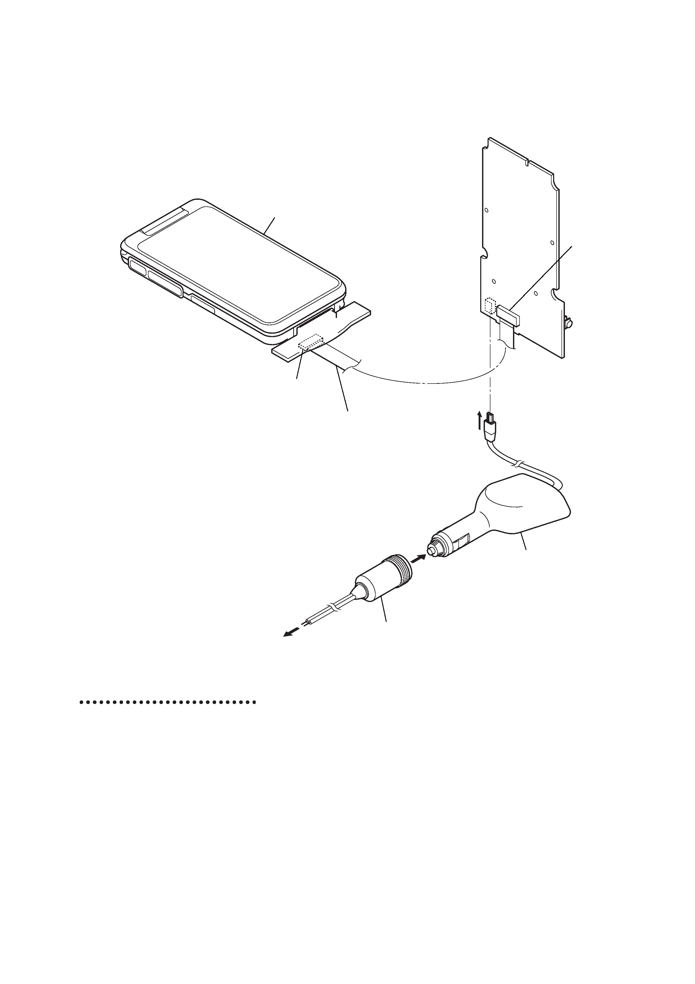
SERVICE POSITION
· In checking the CN/MAIN board, prepare extension jig (Part No. J-2502-079-1) and connect jig (Part No. J-2502-079-2).
CLIE
CN board (CN902)
main board
(CN2)
Connect extension jig (J-2502-079-1)
to the main board (CN2) and
CN board (CN902).
Connect jig (J-2502-079-2) to the
DC-DC converter unit (XA-DC5) and
regulated dc power supply.
regulated dc power supply.
DC-DC converter unit
(XA-DC5)
Computer system
requirements
You need one of the following
systems installed on your computer to
be able to use the PalmTM Desktop for
CLIÉ software and software supplied
on the installation CD-ROM:
·OS: Microsoft Windows 98 Second
Edition, Windows Millennium
Edition, Windows 2000
Professional, Windows XP Home
Edition, Windows XP Professional
·CPU: Pentium II 400MHz or more
(Pentium III 500MHz or more is
recommended)
·RAM: 96MB or more (128MB or
more is recommended, 256MB or
more is recommended for Windows
XP)
·Hard drive space: 200MB (350MB
or more is recommended)
·Display: High Color or more,
800
600 dots or more is
recommended
·CD-ROM drive
·USB port
·Pointing device such as a mouse or
touchpad
For details about StreetFinder®, refer
to the StreetFinder User's Guide.
Design and specifications are subject
to change without notice.

4
PEGA-CC5
CAUTION
You are cautioned that any changes or
modifications not expressly approved in this
manual could void your authorized warranty on
this equipment.
Note:
This equipment has been tested and found to
comply with the limits for a Class B digital device,
pursuant to Part 15 of the FCC Rules. These limits
are designed to provide reasonable protection
against harmful interference in a residential
installation. This equipment generates, uses, and
can radiate radio frequency energy and, if not
installed and used in accordance with the
instructions, may cause harmful interference to
radio communications. However, there is no
guarantee that interference will not occur in a
particular installation. If this equipment does
cause harmful interference to radio or television
reception, which can be determined by turning the
equipment off and on, the user is encouraged to try
to correct the interference by one or more of the
following measures:
Reorient or relocate the receiving antenna.
Increase the separation between the equipment
and receiver.
Connect the equipment into an outlet on a circuit
different from that to which the receiver is
connected.
Consult the dealer or an experienced radio/TV
technician for help.
The car cradle is only for use in the U.S.A.
This device complies with part 15 of the FCC
Rules.
Operation is subject to the following two
conditions:
(1)This device may not cause harmful
interference, and
(2) This device must accept any
interference received, including
interference that may cause undesired
operation.
Caution
IN NO EVENT SHALL SONY BE LIABLE FOR
ANY INCIDENTAL, INDIRECT OR
CONSEQUENTIAL DAMAGES OR OTHER
DAMAGES INCLUDING WITHOUT
LIMITATION LOSS OF PROFITS, LOSS OF
REVENUE, LOSS OF DATA, LOSS OF USE
OF THE PRODUCT OR ANY ASSOCIATED
EQUIPMENT, DOWNTIME, AND
PURCHASER'S TIME RELATED TO OR
ARISING OUT OF THE USE OF THIS
PRODUCT, ITS HARDWARE AND/OR ITS
SOFTWARE.
On the supplied software
·Copyright laws prohibit reproducing the
software or the software manual in whole or
in part or renting the software without the
permission of the copyright holder.
·In no event will SONY be liable for any
financial damage or loss of profits, including
claims made by third parties, arising out of
the use of the software supplied with this
product.
·In the event a problem occurs with this
software as a result of defective
manufacturing, SONY will replace it at
SONY's option or issue a refund. However,
SONY bears no other responsibility.
·The software provided with this product
cannot be used with equipment other than
that which it is designated for use with.
·Please note that, due to continued efforts to
improve quality, the software specifications
may be changed without notice.
·The software library incorporated in the
CLIÉ handheld is based in part on the work of
the Independent JPEG Group.
NOTES
·Sony does not support third party add-on
applications. If you are having a problem
with a third party application, please contact
the developer or publisher of that software.
·The illustrations in this manual may differ
from the actual software.
·Explanations in this manual assume that you
are familiar with basic operations of
Windows®. For how to use your computer
and operating system, please refer to their
respective manuals.
Program © 2003 Sony Corporation, © 2003 Palm,
Inc., or its subsidiaries. All rights reserved.
Documentation © 2003 Sony Corporation
CAUTION
Please contact your nearest Sony dealer regarding
any problems you have with your Sony product.
On the trademarks
Sony, CLIÉ, "Memory Stick", "Memory Stick
Duo", "Memory Stick PRO", "MagicGate
Memory Stick", Jog Dial, PictureGear Studio and
their logos are trademarks of Sony Corporation.
Palm OS, Graffiti, HotSync and the HotSync logo
are registered trademarks of Palm, Inc. and its
subsidiaries, and Palm, Palm Powered, Palm
Desktop, the Palm logo, the Palm Powered logo
and Palm OS5 logo are trademarks of Palm, Inc
and its subsidiaries.
Microsoft and Windows are registered trademarks
of Microsoft Corporation.
Pentium is registered trademarks of Intel
Corporation.
StreetFinder C3 software © 2003, Rand McNally
& Company. All right reserved. StreetFinder and
Rand McNally are registered trademarks of Rand
McNally & Company.
"StreetFinder® C3 Travel Navigation Software" is
referred to as "StreetFinder" in the following
pages.
Bluetooth is a trademark that is owned by the
proprietor and used by Sony under license.
Adobe and Adobe Acrobat Reader are trademarks
of Adobe Systems Incorporated.
All other trademarks are trademarks of their
respective owners.
5
PEGA-CC5
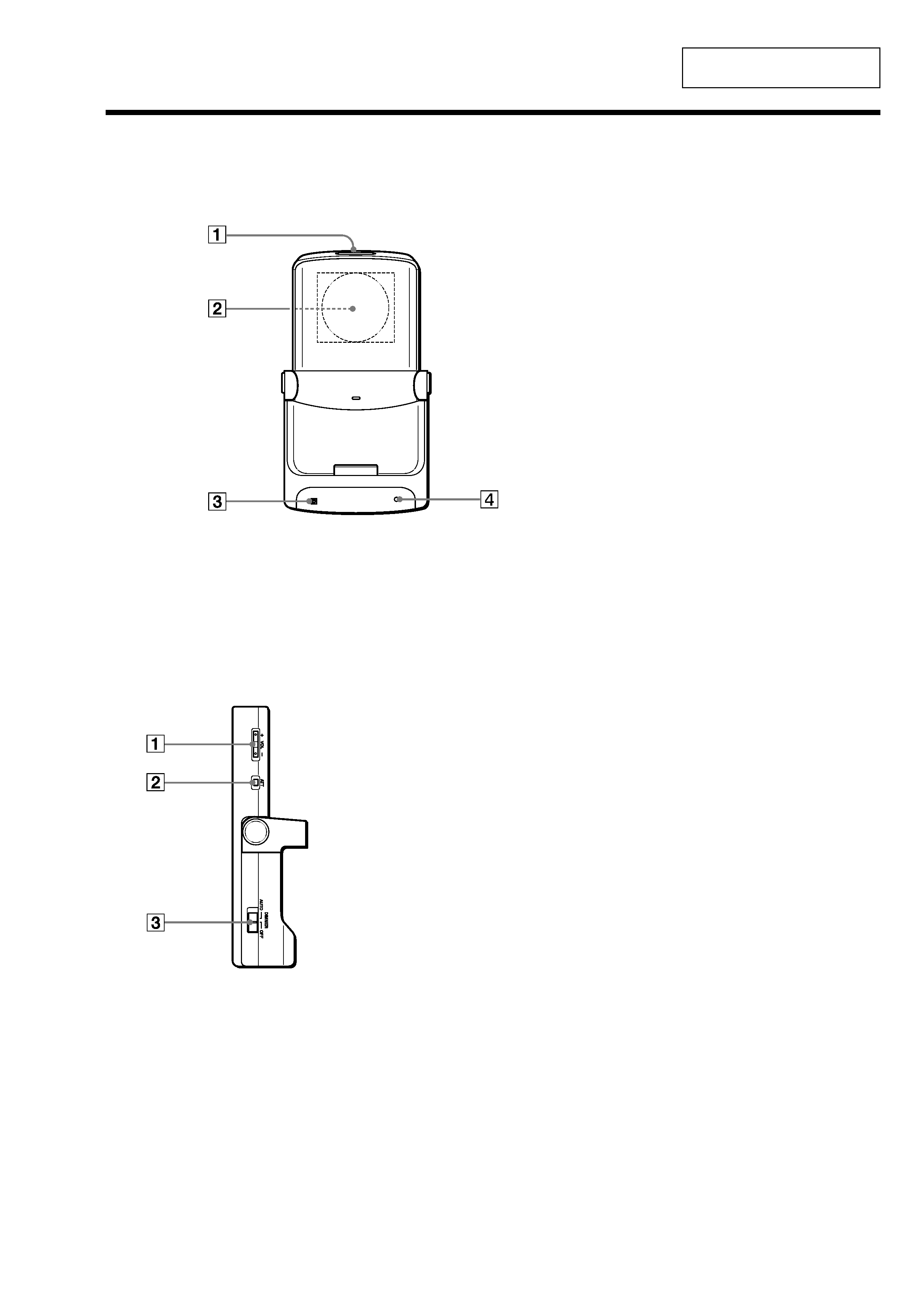
C Receptor for the card remote
commander
D Power indicator LED
Lights green when the power is on.
(It also lights during the in-vehicle
sleep mode and HOLD mode.)
SECTION 2
GENERAL
This section is extracted from
instruction manual.
Location of controls
Front panel
Side panel
A Auto dimmer eye
Receptor for the dimmer.
B Built-in speaker for the Text-
to-voice function (located at the
back of the car cradle)
·While your CLIÉTM handheld is
mounted in the car cradle, the
speaker of your CLIÉ handheld
will be disabled.
·This speaker is only for the Text-
to-voice application; music is not
produced by this speaker.
A VOL +/ buttons for the
built-in speaker
·These buttons control only the
built-in speaker of the car cradle.
·The volume indicator appears only
while you adjust the volume level.
Shortly after you finished adjusting
the volume, the volume indicator
disappears.
·You can adjust the volume level
only when the Text-to-voice
application is being used.
B ATT button for the built-in
speaker
·The ATT function quickly lowers
the volume level.
·Press to lower.
"ATT On" appears on the screen.
·Press again, or press the VOL +
button.
"ATT Off" appears on the screen
and attenuation is canceled.
·You can adjust the volume level
only when the Text-to-voice
application is used.
C Dimmer AUTO/OFF switch
·The Auto dimmer function adjust
the brightness of the screen
automatically, adapting to the
surrounding brightness.
For example, when driving through
a tunnel or at nighttime.
·The brightness default setting is
maximum.
select AUTO to dim the screen
automatically.
select OFF to deactivate the
Dimmer.