PCWA-C150S
SERVICE MANUAL
9-874-610-12
SPECIFICATIONS
For American Area
US Model
For European Area
AEP Model
· Design and specifications are subject to
change without notice.
2.4GHz
Wireless LAN PC Card
Lineup : PCWA-C150S
Ver 2-2002I
Revision History
Protocol support
TCP/IP compliant
Standard
IEEE 802.11b/IEEE 802.11
Radio frequency
2.4 GHz
Modulation method
DS-SS (IEEE 802.11 compliant)
General
Power requirements
3.3 V/5 V (supplied from the computer
through the PC card adapter)
Current
Peak current at transmission: 330 mA
Peak current at reception: 240 mA
Connector
PC Card Card Type II
Dimensions
Approx. 2.2
× 0.2 × 3.6 inches
(Approx. 54
× 5 × 90 mm ) (w/h/d)
(Antenna height: 0.5 inches (Approx. 12 mm))
Mass
Approx. 1.3 oz (Approx. 35 g)
Operating temperature
41
°F to 95°F (5°C to 35°C) (not condensed)
Storage temperature
-4
°F to 140°F (-20°C to 60°C) (not
condensed)
Supplied accessories
See "Unpacking" on page 10.

-- 2 --
Confidential
TABLE OF CONTENTS
1. INSPECTION PROCEDURE
1-1.
Preparation .......................................................................... 4
1-2.
Setting the PC card ............................................................. 4
1-3.
Inspection procedure .......................................................... 4
1-4.
Procedure How To Identify the Error When the
PC Card Is Defective. ......................................................... 5
2. EXPLODED VIEW
2-1.
Exploded Views, Parts List and
Re-assembling Procedure ................................................... 7
2-2.
Accessories and Parts List .................................................. 7
History of the changes is shown as the
"Revision History" at the end of this data.

-- 3 --
Information in this document is subject to change without notice.
Sony, VAIO and CLIE are trademarks or registered trademarks of
Sony. Microsoft, Windows, Windows Media, Outlook, Bookshelf
and other Microsoft products are trademarks or registered trademarks
of Microsoft Corporation in the United States and other countries.
The word Bluetooth and the Bluetooth logo are trademarks of
Bluetooth SIG, Inc. AMD, AMD logo, AMD Duron and
combinations thereof, 3DNow!, are trademarks of Advanced Micro
Devices, Inc. Intel Inside logo, Pentium and Celeron are trademarks
or registered trademarks of Intel Corporation. Transmeta, the
Transmeta logo, Crusoe Processor, the Crusoe logo and
combinations thereof are trademarks of Transmeta Corporation in
the USA and other countries. Graffiti, HotSync, PalmModem, and
Palm OS are resistered trademarks, and the Hotsync logo and Palm
are trademarks of Palm, Inc. or its subsidiaries. (M) and Motrola
are trademarks of Motrora, Inc. Other Motrola products and services
with (R) mark like Dragomball are the trademarks of Motrola, Inc.
All other names of systems, products and services in this manual
are trademarks or registered trademarks of their respective owners.
In this manual, the (TM) or (R) mark are not specified.
Service and Inspection Precautions
1. Obey precautionary markings and instructions
Labels and stamps on the cabinet, chassis, and components identify areas
requiring special precautions. Be sure to observe these precautions, as well
as all precautions listed in the operating manual and other associated
documents.
2. Use designated parts only
The set's components possess important safety characteristics, such as
noncombustibility and the ability to tolerate large voltages. Be sure that
replacement parts possess the same safety characteristics as the originals.
Also remember that the 0 mark, which appears in circuit diagrams and
parts lists, denotes components that have particularly important safety
functions; be extra sure to use only the designated components.
3. Always follow the original design when mounting
parts and routing wires
The original layout includes various safety features, such as inclusion of
insulating materials (tubes and tape) and the mounting of parts above the
printer board. In addition, internal wiring has been routed and clamped so
as to keep it away from hot or high-voltage parts. When mounting parts or
routing wires, therefore, be sure to duplicate the original layout.
4. Inspect after completing service
After servicing, inspect to make sure that all screws, components, and wiring
have been returned to their original condition. Also check the area around
the repair location to ensure that repair work has caused no damage, and
confirm safety.
5. When replacing chip components...
Never reuse components. Also remember that the negative side of tantalum
capacitors is easily damaged by heat.
6. When handling flexible print boards...
· The temperature of the soldering-iron tip should be about 270C.
· Do not apply the tip more than three times to the same pattern.
· Handle patterns with care; never apply force.
Caution Markings for Lithium/Ion Battery - The following or similar
texts shall be provided on battery pack of equipment or in both the
operating and the service instructions.
CAUTION: Danger of explosion if battery is incorrectly replaced.
Replace only with the same or equivalent type recommended by
the manufacturer. Discard used batteries according to the
manufacturer's instructions.
CAUTION: The battery pack used in this device may present a fire
or chemical burn hazard if mistreated. Do not disassemble, heat
above 100
°C (212°F) or incinerate.
Dispose of used battery promptly.
Keep away from children.
Confidential
-- 4 --
Confidential
SECTION 1
INSPECTION PROCEDURE
1-1. Preparation
Required equipment
· Personal computer having the Card Bus interface, in which
WindowsXP/2000/Me is installed. (Called PC hereafter.)
· PCWA-A100/200
· Setup CD-ROM supplied with the PCWA-C150S
Sony Wireless LAN Client Manager
(1-663-054-1
) (US)
(1-663-054-2
) (AEP)
Refer :
· Wireless Test tool_C150SU (J-2507-378-
)
Installing the software
· Refer to the " GUIDE SIMPLE EXPLANATION (Quick Start
Guide)" supplied with PCWA-C150S
(4-663-056-1
) (US)
(4-667-590-2
) (AEP)
· Create a shortcut icon of "PC Card Settings" on the Windows
screen.
Inspection specifications
Inspection Conditions
Terminal
Notebook
PC
Notebook
PC
Notebook
PC
Every notebook PC should be placed about 50 cm or more apart from the terminal.
PC card
1-2. Setting the PC Card
(When the PC card is set once, the setup is memorized.)
1. Double-click the "PC Card Setting" icon.
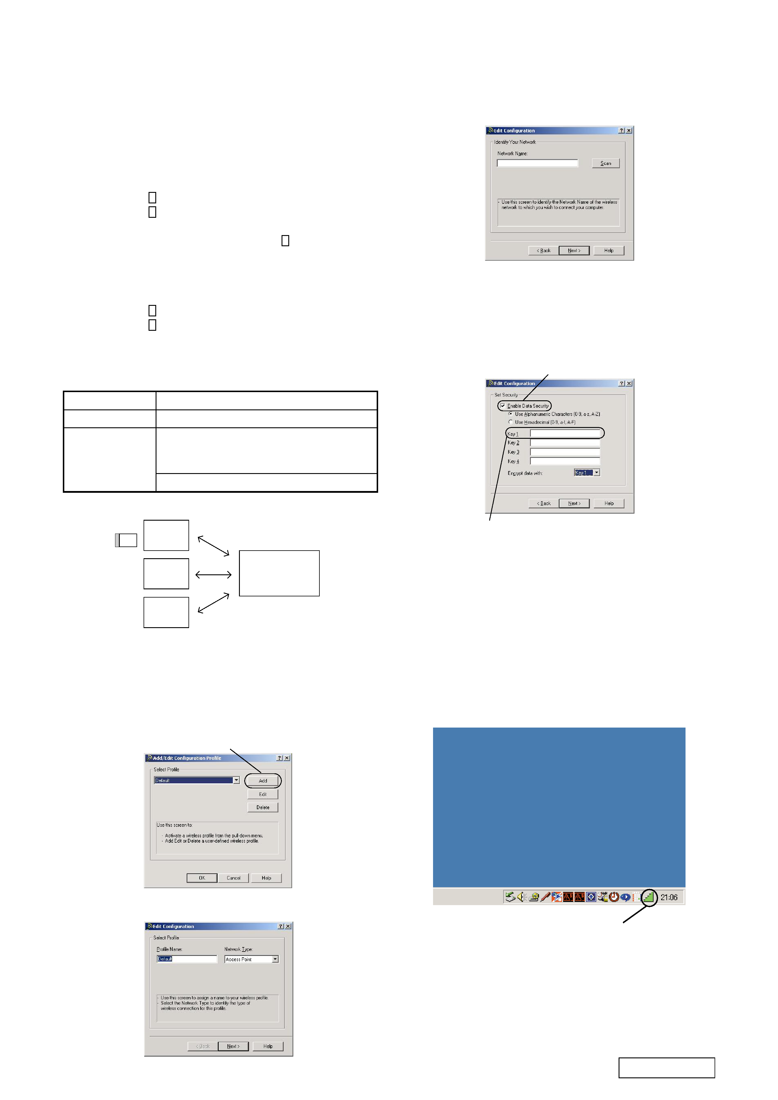
2. Click "Add" on the "Add/Edit Add/Edit Configration Profile -
Select Profile" screen.
3. Select "Access Point" on the "Edit configration - Select Profile"
screen "Network Type". Then click "Next".
Click
4. Click "Scan" on the "Edit configration-Identity your Network"
screen to search the access pint within the communication area.
2. Type the lower five digits of access point SSID
1. Click the check box.
1-3. Inspection Procedure
1. Double-click the "Sony Wireless LAN Client Manager" icon
on the task bar.
Remarks:
· When the PC card is not installed, the icon lights in gray.
· When the PC card is installed, the icon changes from gray to
green.
Sony WirelessLAN icon
Item
Card Diagnostics
LINK Test
Specifications
OK should appear on all items.
The SNR gauge should light in green.
If it lights in yellow, the equipment is
diagnosed as defective.
The signal level should be -55 dBm or more.
5. Select the access point to connect (it appears in the "Network
name scanning" dialog box if it exists), and click "OK".
6. The display will return to the screen of step 4. Click "Next".
7. Click the check box of the "Data security ON" on the "Edit
configration - Set Security" screen. Type the key (lower five
digits of access point SSID) in the key 1. Click "Next".
8. Select "OFF" on the "Edit configration - Power management"
screen. Click "Next".
9. Click "Finish" on the "Edit configration - TCP/IP Behavior"
screen.
This is the end of setting.
-- 5 --
Confidential
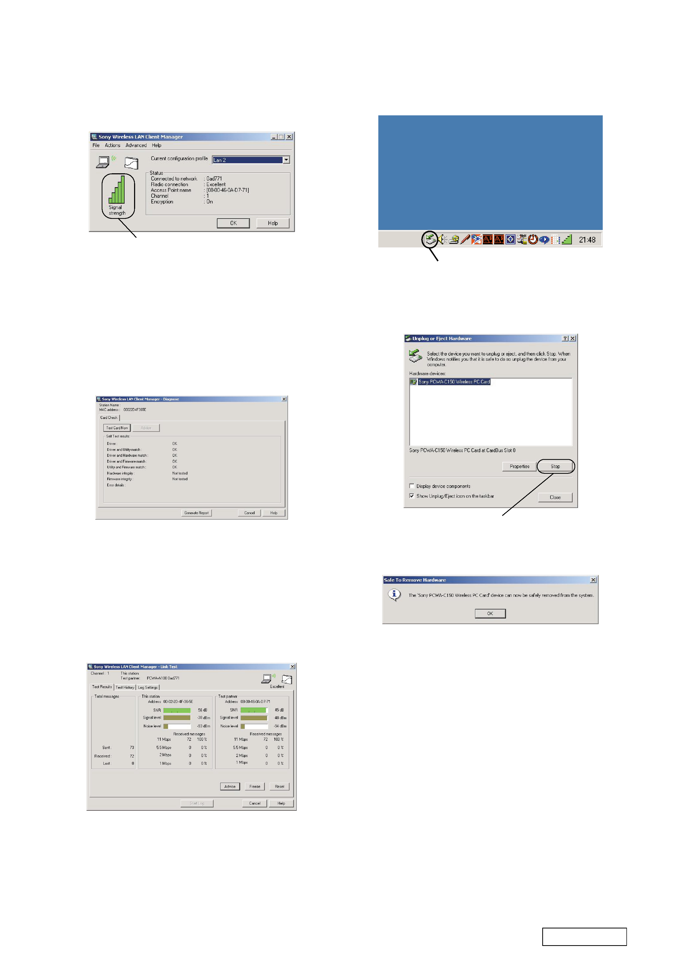
Signal strength graph
2. Insert the PC card in a personal computer.
When the PC card is a good one, the "Signal strength" graph
on the "Sony Wireless LAN Client Manager" screen changes
from gray to green.
Remarks: If the color does not change:
· The main power of the access point is not turned on.
· The PC card is defective.
< Executing the card diagnosis >
3. Select "Advanced"
"Card diagnosis" on the "Sony Wireless
LAN Client Manager" screen.
4. The diagnosis screen will appear. Click "Test card now". Check
that "OK" appears on all items.
[Card Diagnosis screen]
5. Press the "Cancel" button to end the card diagnosis.
< Executing the LINK Test >
6. Select "Advanced"
"LINK Test" on the "Sony Wireless LAN
Client Manager" screen.
7. The LINK Test screen will appear. Check "SNR" and "Signal
level" in the "This station" and the "Test Partner".
[LINK Test screen]
< Removing the PC card >
9. Double-click the "Unplug or Eject Hardware" icon.
10. The "Unplug or Eject Hardware" screen will appear. Select
"Sony PCWA-C150Wireless PC Card" and click the "Stop"
button.
Unplug or Eject Hardware icon
11. The "Safe to Remove Hardware" screen will appear. Select
"Sony PCWA-C150Wireless PC Card" and click OK. The
following message appears.
Click
Select "OK" and remove the PC card.
End of inspection
When you want to inspect other cards continuously, repeat steps 1
to 11 of section 1-3.
1-4. Procedure How To Identify the Error When the
PC Card Is Defective.
Preparation:
· Prepare the dummy antenna block.
1. Separate the card and antenna block.
2. Install the dummy antenna block to the card.
3. Perform inspection of steps 1 to 11 of item 1-3.
4. If the product works satisfactorily, the antenna block is
diagnosed to be a good antenna block.
5. If the product does not work satisfactorily, the card block is
defective.
Inspection criterion
· The "SNR" gauge should light in green. If the "SNR" gauge
lights in yellow, the equipment is diagnosed as defective.
· The "Signal level" should be -55 dBm or more.
8. Press the "Cancel" button to end the inspection.