PCWA-A100/A200/C100
SERVICE MANUAL
WIRELESS LAN ACCESS POINT
WIRELESS LAN PC CARD
9-928-159-13
PC Card
(PCWA-C100)
SPECIFICATIONS
Access Point
(PCWA-A100/A200)
Communication distance
Approx. 100 m (approx. 330 feet) with no
obstacles (The communicable distance
depends on theenvironment.)
Maximum number of units
connected
49 units (number of clients)
(Recommended number of clients is 16 or
less)
Protocol support
TCP/IP, NetBEUI
Standard
IEEE802.11b/IEEE802.11
Radio frequency
2.4 GHz
Modulation method
DS-SS (IEEE802.11 compliant)
General
Power requirements
100 to 240 V AC, 50/60 Hz
Power consumption
Approx. 5 W
Dimensions
With stand: Approx. 156 134.5 53 mm
(approx. 61/4 x 53/8 x 21/8 inches) (w/h/d)
Without stand: Approx. 156 125 35 mm
(approx. 6 1/4 x 5 x 17/16 inches) (w/h/d)
Mass
PCWA-A100: Approx. 480 g (approx. 17 oz.)
PCWA-A200: Approx. 450 g (approx. 16 oz.)
(excluding the unit stand and the AC power adapter)
Operating temperature
5
°C to 35°C (41°F to 95°F)
(not condensed)
Environment temperature
-20
°C to 60°C (-4°F to 140°F)
(not condensed)
Supplied accessories
· Wireless LAN Access Point
· Unit stand
· AC power adapter
· Telephone cable (PCWA-A100 only)
· Telephone jack splitter (PCWA-A100 only)
· Wireless LAN Access Point
Operating Instructions
· Other printed materials
· Wireless LAN PC card set
Note
See the Wireless LAN PC Card Operating
Instructions regarding the WirelessLAN
PC card set.
Protocol support
TCP/IP, NetBEUI compliant
Standard
IEEE802.11b/IEEE802.11
Radio frequency
2.4 GHz
Modulation method
DS-SS (IEEE802.11 compliant)
General
Power requirements
5 V AC (supplied from the computer
through the PC card adapter)
Current
Peak current at transmission: 280 mA
Peak current at reception: 180 mA
Connector
PC card slot Type-II
Dimensions (approx.)
Approx. 118 x 5 x 54 mm
(approx. 43/4 x 7/32 x 21/4 inches) (w/h/d)
(Antenna height: 8.7mm ( 11/32 inches))
Mass
Approx. 55 g (approx. 2 oz)
Operating temperature
5
°C to 35°C (41°F to 95°F)
Environment temperature
-20
°C to 60°C (-4°F to 140°F)
Supplied accessories
· Wireless LAN PC Card
· PC card case
· CD-ROM (Setup disk)
· Operating Instructions
· END-USER LICENSE AGREEMENT
· Other printed materials
Access Point
PC Card
Design and specifications are subject
to changewithout notice.
(not condensed)
(not condensed)
Discard the Service Manual 9-928-159-12, 9-928-159-11, 9-874-304-11
in accordance with issuance of this Service Manual.
US Model
Canadian Model
PCWA-A100/A200/C100
AEP Model
PCWA-A200/C100
UK Model
PCWA-A200
Ver 3-2001J
All the supplementary
information are attached
at the end of data files.
Update List

-- 2 --
PCWA-A100/A200/C100 (UC/AEP/UK)
Information in this document is subject to change without notice.
Sony and VAIO are trademarks of Sony. Intel logo and Intel Inside
logo are registered trademarks of Intel Corporation. Pentium MMX
is a trademark of Intel Corporation. Microsoft, MS-DOS, Windows,
the Windows 95 and Windows 98 logo are trademarks of Microsoft
Corporation.
All other trademarks are trademarks or registered trademarks of
their respective owners. Other trademarks and trade names may be
used in this document to refer to the entitles claiming the marks and
names or their produces. Sony Corporation disclaims any proprietary
interest in trademarks and trade names other than its own.
Service and Inspection Precautions
1. Obey precautionary markings and instructions
Labels and stamps on the cabinet, chassis, and components identify areas
requiring special precautions. Be sure to observe these precautions, as well
as all precautions listed in the operating manual and other associated
documents.
2. Use designated parts only
The set's components possess important safety characteristics, such as
noncombustibility and the ability to tolerate large voltages. Be sure that
replacement parts possess the same safety characteristics as the originals.
Also remember that the 0 mark, which appears in circuit diagrams and
parts lists, denotes components that have particularly important safety
functions; be extra sure to use only the designated components.
3. Always follow the original design when mounting
parts and routing wires
The original layout includes various safety features, such as inclusion of
insulating materials (tubes and tape) and the mounting of parts above the
printer board. In addition, internal wiring has been routed and clamped so
as to keep it away from hot or high-voltage parts. When mounting parts or
routing wires, therefore, be sure to duplicate the original layout.
4. Inspect after completing service
After servicing, inspect to make sure that all screws, components, and wiring
have been returned to their original condition. Also check the area around
the repair location to ensure that repair work has caused no damage, and
confirm safety.
5. When replacing chip components...
Never reuse components. Also remember that the negative side of tantalum
capacitors is easily damaged by heat.
6. When handling flexible print boards...
· The temperature of the soldering-iron tip should be about 270C.
· Do not apply the tip more than three times to the same pattern.
· Handle patterns with care; never apply force.
Caution: Remember that hard disk drives are easily damaged by
vibration. Always handle with care.
Caution Markings for Lithium/Ion Battery - The following or similar
texts shall be provided on battery pack of equipment or in both the
operating and the service instructions.
CAUTION: Danger of explosion if battery is incorrectly replaced.
Replace only with the same or equivalent type recommended by
the manufacturer. Discard used batteries according to the
manufacturer's instructions.
CAUTION: The battery pack used in this device may present a fire
or chemical burn hazard if mistreated. Do not disassemble, heat
above 100
°C (212°F) or incinerate.
Dispose of used battery promptly.
Keep away from children.
ATTENTION AU COMPOSANT AYANT RAPPORT
À LA SÉCURITÉ!
LES COMPOSANTS IDENTIFÉS PAR UNE MARQUE 0 SUR LES
DIAGRAMMES SCHÉMATIQUES ET LA LISTE DES PIÈCES SONT
CRITIQUES POUR LA SÉCURITÉ DE FONCTIONNEMENT. NE
REMPLACER CES COMPOSANTS QUE PAR DES PIÈSES SONY
DONT LES NUMÉROS SONT DONNÉS DANS CE MANUEL OU
DANS LES SUPPÉMENTS PUBLIÉS PAR SONY.
Confidential

-- 3 --
PCWA-A100/A200/C100 (UC/AEP/UK)
Confidential
TABLE OF CONTENTS
1. OVERVIEW
1-1.
Access Point .................................................................... 1-1
1-2.
PC Card ........................................................................... 1-1
2. SERVICE PROGRAM
2-1.
How to Implement the Service Inspection of the Access
point / PC Card ................................................................ 2-1
2-1-1. Preparations for Inspection .............................................. 2-1
2-1-2. Inspecting the Access point / Inspecting the PC Card ..... 2-2
2-1-3. Wireless LAN Link Test .................................................. 2-2
2-1-4. Ethernet Link Test ........................................................... 2-3
2-2.
Setup of Desktop PC ....................................................... 2-6
2-2-1. Required Tools ................................................................. 2-6
2-2-2. Network Setting of Desktop PC ...................................... 2-6
2-2-3. Setting the Magic DHCP Server ..................................... 2-7
2-3.
Set up of Notebook PC .................................................... 2-7
2-3-1. Required Tools ................................................................. 2-7
2-3-2. Network Setting of Notebook PC .................................... 2-7
2-4.
Access point Modem Inspection Procedure
(PCWA-A100 only) ......................................................... 2-7
2-4-1. Preparation ....................................................................... 2-7
2-4-2. Inspection ........................................................................ 2-8
Extracted from the PCWA-C100 Instruction Manual ..... 2-9
2-5.
Checking Symptoms Pointed Out by User
(Final Check) ................................................................. 2-21
2-6.
How to Return to the Factory Settings .......................... 2-21
2-6-1. Setup .............................................................................. 2-21
2-6-2. Resetting the Access Point ............................................ 2-22
2-6-3. Returning the current settings of the Access Point to
the ex-factory status and upgrading the firmware ......... 2-22
2-6-4. Specifying the IP Address
When Windows 98SE, Me is used ................................ 2-24
2-6-5 Specifying the IP Address
When Windows 2000 is used ........................................ 2-25
2-6-6. Error Messages .............................................................. 2-27
3. ACCESSORIES & PACKING MATERIALS ········ 3-1
1-1
PCWA-A100/A200/C100 (UC/AEP/UK)
Confidential
(END)
SECTION 1
OVERVIEW
This section is extracted from
instruction manual (4-647-079-14).
1-1. Access Point
1-2. PC Card
This section is extracted from
instruction manual (4-647-085-14).
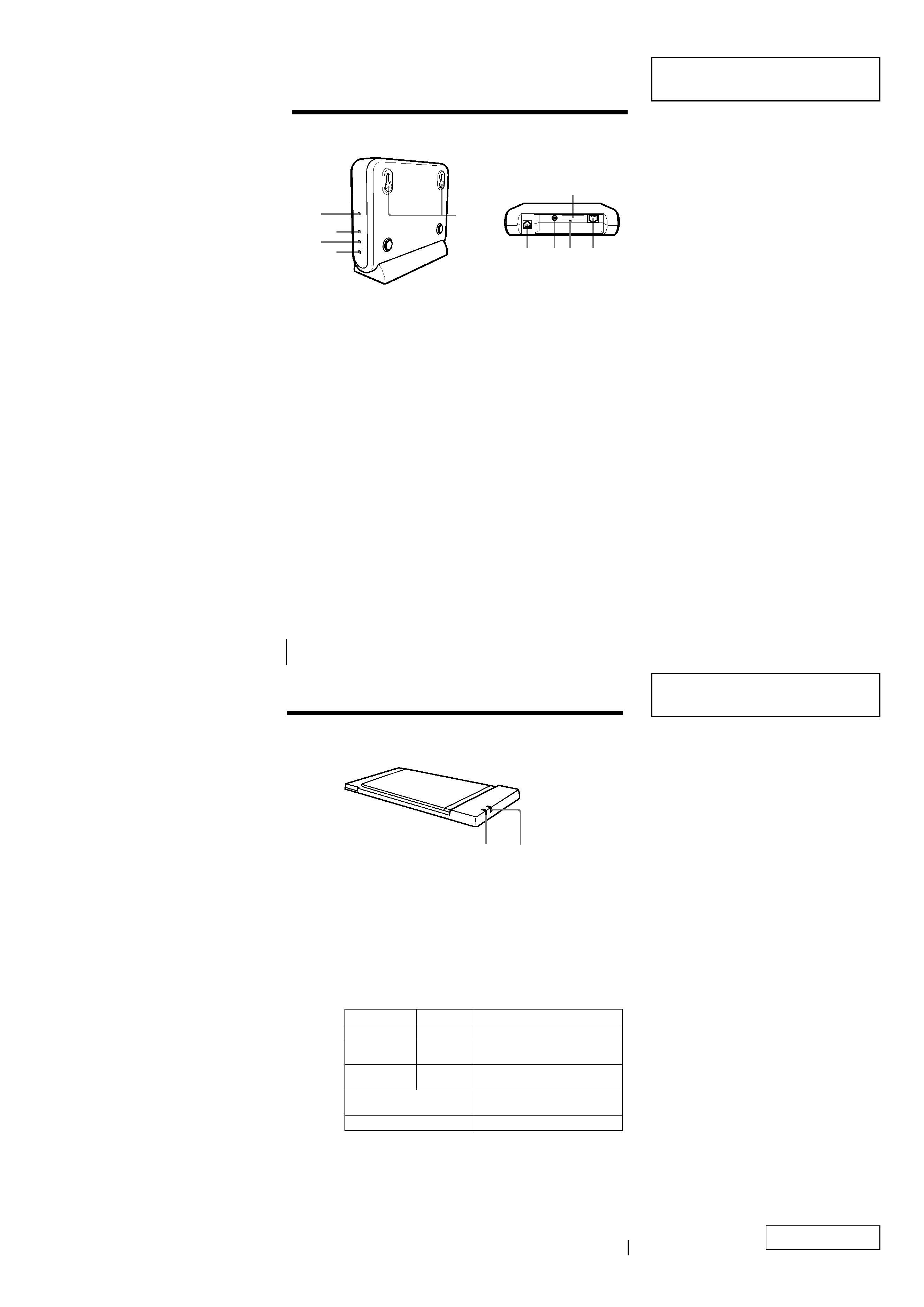
13
1
DATA indicator
Lights while data exchange is in progress.
2
LINK indicator
Lights while your computer is connected to the wireless LAN.
Description on the indicators
DATA
LINK
Description
Flashing (green)
Lit (green)
Normal communications.
Fast Flashing
Lit (green)
Peer to Peer mode
(green)
Off
Lit (green)
The PC card is powered, but no
communication is taking place.
Flashing at 10 sec intervals
The PC card is operating, but no
connection is established.
Off
The PC card is powered off.
Indicators
12
12
* Not included with the PCWA-A200.
1 POWER indicator
Lights while power is supplied.
2 WIRELESS indicator
Lights when data is being exchanged on a wireless LAN.
3 ETHERNET indicator
Lights while data exchange is in progress through the 10BASE-T
connector.
4 PHONE indicator (PCWA-A100 only)
Lights while data exchange is in progress through the LINE/
PHONE connector.
5 Wall-mounting holes
6 LINE/PHONE connector (RJ-11) (PCWA-A100 only) (page 14)
Connects to the telephone cable.
7 DC IN 9V jack (page 19)
Connects to the AC power adapter.
8 Reset switch
9 ID label (page 20)
The Access Point ID and other information are printed on this label.
0 10BASE-T connector (RJ-45) (page 15)
Connects to a cable modem, DSL modem, ISDN router, or hub
through an Ethernet cable.
Parts and indicators (Wireless LAN Access Point)
9
LINE/
PHONE
DC IN 5V
10BASE-T
1
2
3
4
5
67 8
0
*
*
2-1
PCWA-A100/A200/C100 (UC/AEP/UK)
Confidential
SECTION 2
SERVICE PROGRAM
· When repairing is completed, be sure to return all the settings to the default setting when
shipped from the factory, before returning the machine to customer.
· This section describes the SERVICE PROGRAM for Windows 98SE, Me and 2000.
This section does not apply to Windows XP.
· Procedure to run the SERVICE PROGRAM of Windows XP is different from that of
Windows 98SE, Me and 2000.
· To inspect the Access point / PC Card, the following inspection software is required.
Tool No.: J-2500-477-3 (CD-ROM)
2-1. How to Implement the Service Inspection of the Access point / PC Card
2-1-1. Preparations for Inspection
Preparation for inspecting the desktop PC
Complete the setup in advance before starting inspection. (Refer to Section "2-2. Setup of Desktop PC".)
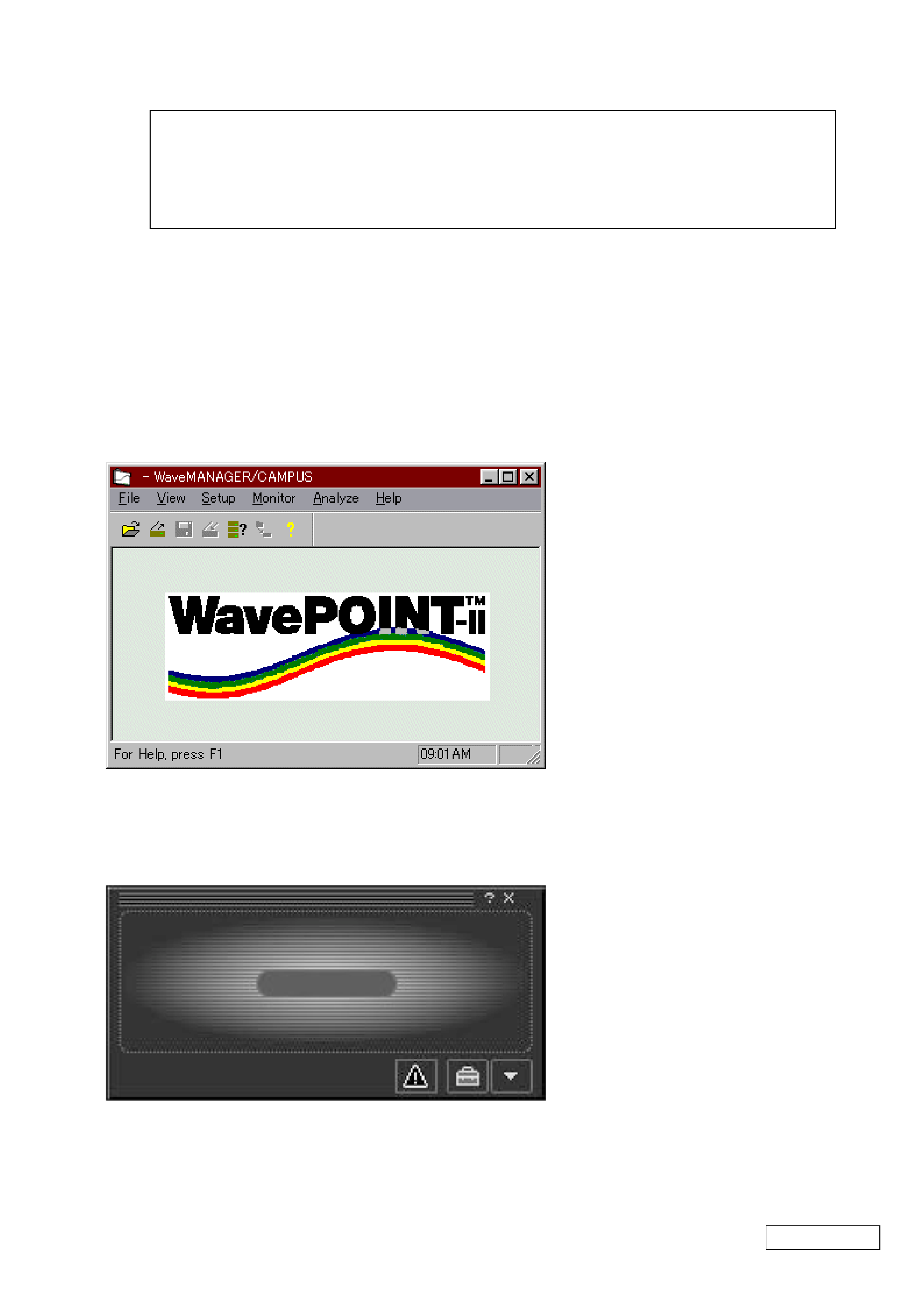
Start up [Amea.exe] of the desktop PC.
Preparation for inspecting the notebook PC
Complete the setup in advance before starting inspection. (Refer to Section "2-3. Setup of Notebook PC".)
Start up [Wireless Palette] of the Notebook PC. (For the startup procedure, refer to page 57 of the PCWA-C100 Instruction Manual
"To establish communication with the Access Point", step 1.)
Connect the AC adapter to the AC outlet.
Connect the Ethernet cross-cable to the Ethernet terminal of the desktop PC.