SERVICE MANUAL
PERSONAL COMPUTER VAIO
US Model
Canadian Model
PCV-LX810/LX910
Specifications
S400
9-874-310-13
Ver 3-2005B
Revision History
2
PCV-LX810/LX910 (UC)
Confidential
CAUTION
Danger of explosion if battery is incorrectly replaced.
Replace only with the same or equivalent type
recommended by the manufacturer.
Dispose of used batteries according
to the manufacturer's instructions.

3
PCV-LX810/LX910 (UC)
Confidential
TABLE OF CONTENTS
1.
OPERATION
2.
DISASSEMBLY
2-1. Flow Chart ............................................................... 2-1
2-2. Main Unit ................................................................ 2-2
2-3. Stand (Accessory) ................................................... 2-2
2-4. HDD ........................................................................ 2-3
2-5. CD-RW/DVD-ROM ................................................ 2-3
2-6. Modem Card (PCI) .................................................. 2-4
2-7. Riser Card, Riser Support ....................................... 2-4
2-8. Switching Power Supply ......................................... 2-5
2-9. Memory (DIMM) .................................................... 2-6
Memory (DIMM) Installation ................................. 2-6
2-10. CPU ......................................................................... 2-7
CPU Installation ...................................................... 2-7
2-11. Mother Board .......................................................... 2-8
2-12. Neck Cover (Rear), Arm Cover (Rear) ................... 2-9
2-13. Arm Cover (Front), Neck Cover (Front),
Center Cover ......................................................... 2-10
2-14. Display Ass'y ........................................................ 2-11
2-15. IFX-120 Mounted PWB ........................................ 2-12
2-16. Display Unit, ANL-25 Mounted PWB ................. 2-12
2-17. LCD Panel, IFX-127 Mounted PWB ................... 2-13
2-18. Inverter Unit,
IFX-119 (S2)/IFX-119 (T) Mounted PWB .......... 2-14
2-19. Main Electric Parts Arrangement
Main Section ......................................................... 2-15
Display Section ..................................................... 2-15
3.
MOTHER BOARD DESCRIPTION ......... 3-1
4.
PROGRAMS FOR SERVICE .................... 4-1
5.
SERVICE INFORMATION
5-1. Jumper Setting on Hard Disk Drive ....................... 5-1
5-2. Jumper Setting of Mother Board ............................ 5-2
6.
BLOCK DIAGRAM
6-1. Mother Board .......................................................... 6-1
6-2. LCD Board .............................................................. 6-3
7.
FRAME HARNESS
7-1. Connector List ......................................................... 7-1
7-2. Frame Harness Diagram ......................................... 7-5
8.
REPAIR PARTS LIST
8-1. Exploded Views and Parts List (Main Section) ...... 8-1
8-2. Exploded Views and Parts List (Display Section)
(PCV-LX810) .......................................................... 8-3
8-3. Exploded Views and Parts List (Display Section)
(PCV-LX910) .......................................................... 8-5
8-4. Accessories and Parts List ...................................... 8-8
· Abbreviations
UC
: US model/Canadian model
2-1
PCV-LX810/LX910 (UC)
Confidential
SECTION 2
DISASSEMBLY
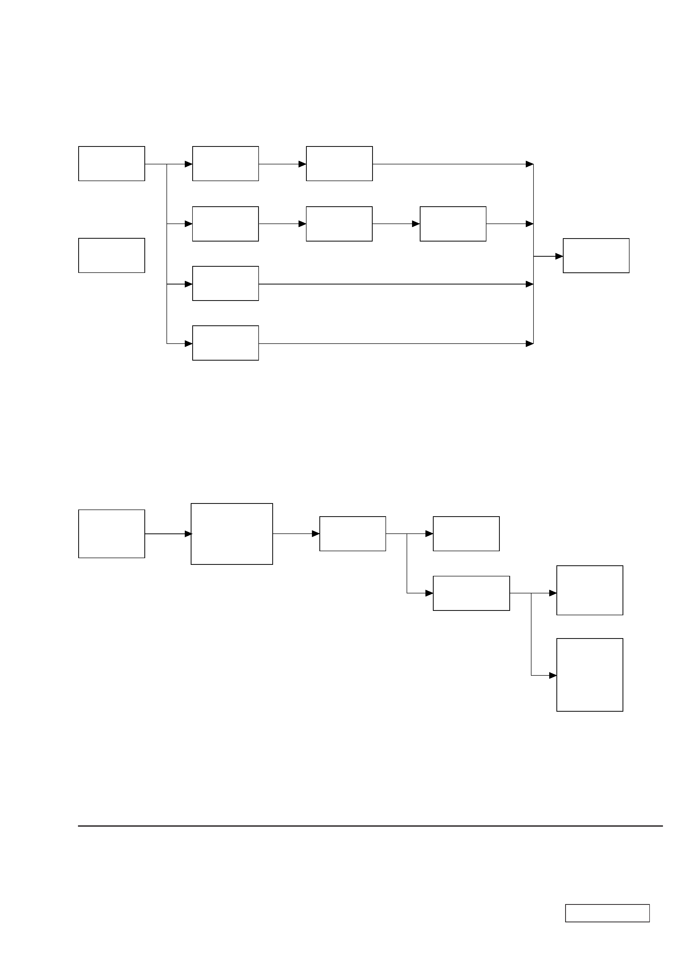
2-1.
FLOW CHART
·
Ps-s denotes the page concerned.
·
HDD has a low resistance to vibration, requiring careful handling.
· DISPLAY SECTION
DISPLAY
ASS'Y
P2-11
IFX-120
MOUNTED
PWB
P2-12
LCD PANEL,
IFX-127
MOUNTED
PWB
P2-13
INVERTER
UNIT,
IFX-119 (S2)/
IFX-119 (T)
MOUNTED
PWB
P2-14
DISPLAY UNIT,
ANL-25
MOUNTED PWB
P2-12
P2-9
NECK COVER
(REAR),
ARM COVER
(REAR)
P2-10
ARM COVER
(FRONT),
NECK COVER
(FRONT),
CENTER COVER
· MAIN SECTION
MODEM
CARD (PCI)
P2-4
RISER CARD,
RISER
SUPPORT
P2-4
SWITCHING
POWER
SUPPLY
P2-5
MEMORY
(DIMM)
P2-6
MOTHER
BOARD
P2-8
CPU
P2-7
P2-3
CD-RW/
DVD-ROM
P2-3
MAIN UNIT
HDD
P2-2
STAND
(ACCESSORY)
P2-2
2-2
PCV-LX810/LX910 (UC)
Confidential
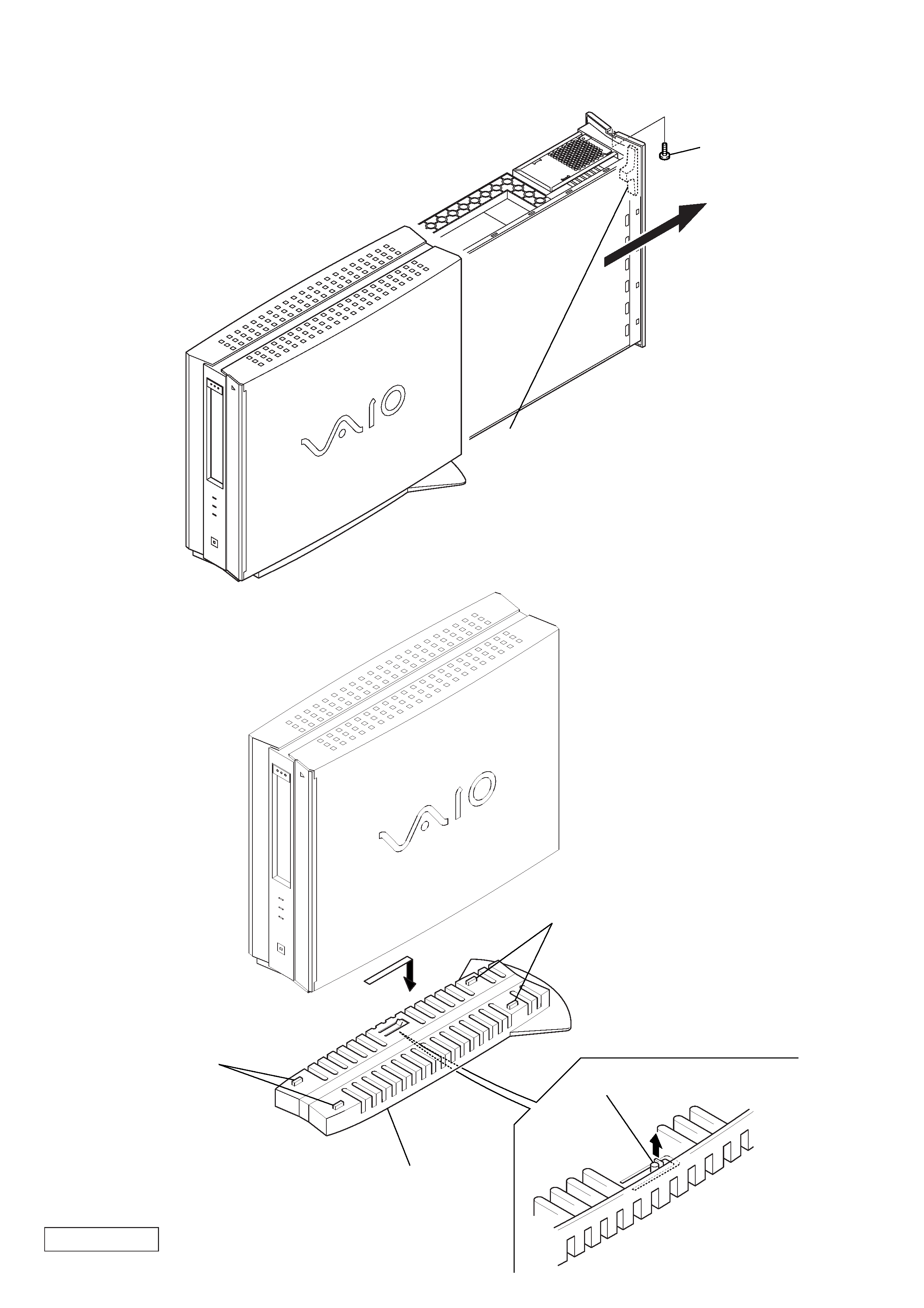
2-2.
MAIN UNIT
2-3.
STAND (ACCESSORY)
A
1
screw (B3
× 6)
2
Hold the release handle and
pull out the main unit in the
direction of arrow A.
2
two claws
2
two claws
1
claw
A
3
Remove the stand in the
direction of arrow A.