SERVICE MANUAL
PCV-L620
US Model
Specifications
PERSONAL COMPUTER VAIO
9-928-356-12
S400
Ver 2-2004C
Revision History
2
PCV-L620

3
PCV-L620
TABLE OF CONTENTS
1.
OPERATION
2.
DISASSEMBLY
2-1. Flow Chart ........................................................................ 2-1
2-2. Memory Card ................................................................... 2-2
2-3. Top Cover ......................................................................... 2-2
2-4. HDD ................................................................................. 2-3
2-5. Drive Holder, FDD, DVD-ROM ..................................... 2-3
2-6. Modem Card ..................................................................... 2-4
2-7. Riser Support, Riser Card ................................................ 2-4
2-8. Memory (DIMM) ............................................................. 2-5
Memory (DIMM) Installation .......................................... 2-5
2-9. CPU .................................................................................. 2-6
Change the Fan ................................................................. 2-6
2-10. SWX-26A, LEX-14A Mount ........................................... 2-7
2-11. Power Supply ................................................................... 2-7
2-12. Drive Support ................................................................... 2-8
2-13. Main Board ....................................................................... 2-8
2-14. LCD Ass'y ........................................................................ 2-9
2-15. Rear Cover ..................................................................... 2-10
2-16. IFX-94 Mount, Inverter Unit ......................................... 2-10
2-17. Front Cover .................................................................... 2-11
2-18. LCD Panel ...................................................................... 2-11
2-19. Main Electric Parts Arrangement .................................. 2-12
Main Section .................................................................. 2-12
Display Section .............................................................. 2-12
3.
MOTHERBOARD DESCRIPTION ...................... 3-1
4.
PROGRAMS FOR SERVICE
4-1. Diagnostics for service ..................................................... 4-1
4-1-1.General ............................................................................. 4-1
4-1-2.Start-up ............................................................................. 4-1
4-1-3.Test Items ......................................................................... 4-1
4-1-4.Test Result ........................................................................ 4-1
4-1-5.Memory Stick Test ........................................................... 4-1
4-1-6.LCD Test .......................................................................... 4-1
4-1-7.PC Card Test ..................................................................... 4-2
4-2. BIOS DMI Data Rewriting Method ................................ 4-2
5.
SERVICE INFORMATION
5-1. Jumper Setting on Hard Disk Drive ................................ 5-1
5-2. Jumper Setting of Main Board ......................................... 5-2
6.
BLOCK DIAGRAM ................................................... 6-1
7.
FRAME HARNESS
7-1. Connector List .................................................................. 7-1
7-2. Frame Harness Diagram .................................................. 7-7
8.
REPAIR PARTS LIST
8-1. Exploded views and Parts List (Main Section) ............... 8-1
8-2. Exploded views and Parts List (Display Section) ........... 8-3
8-3. Accessories and Parts List ............................................... 8-5
8-4. BarCord Label .................................................................. 8-6
2-1
PCV-L620
SECTION 2
DISASSEMBLY
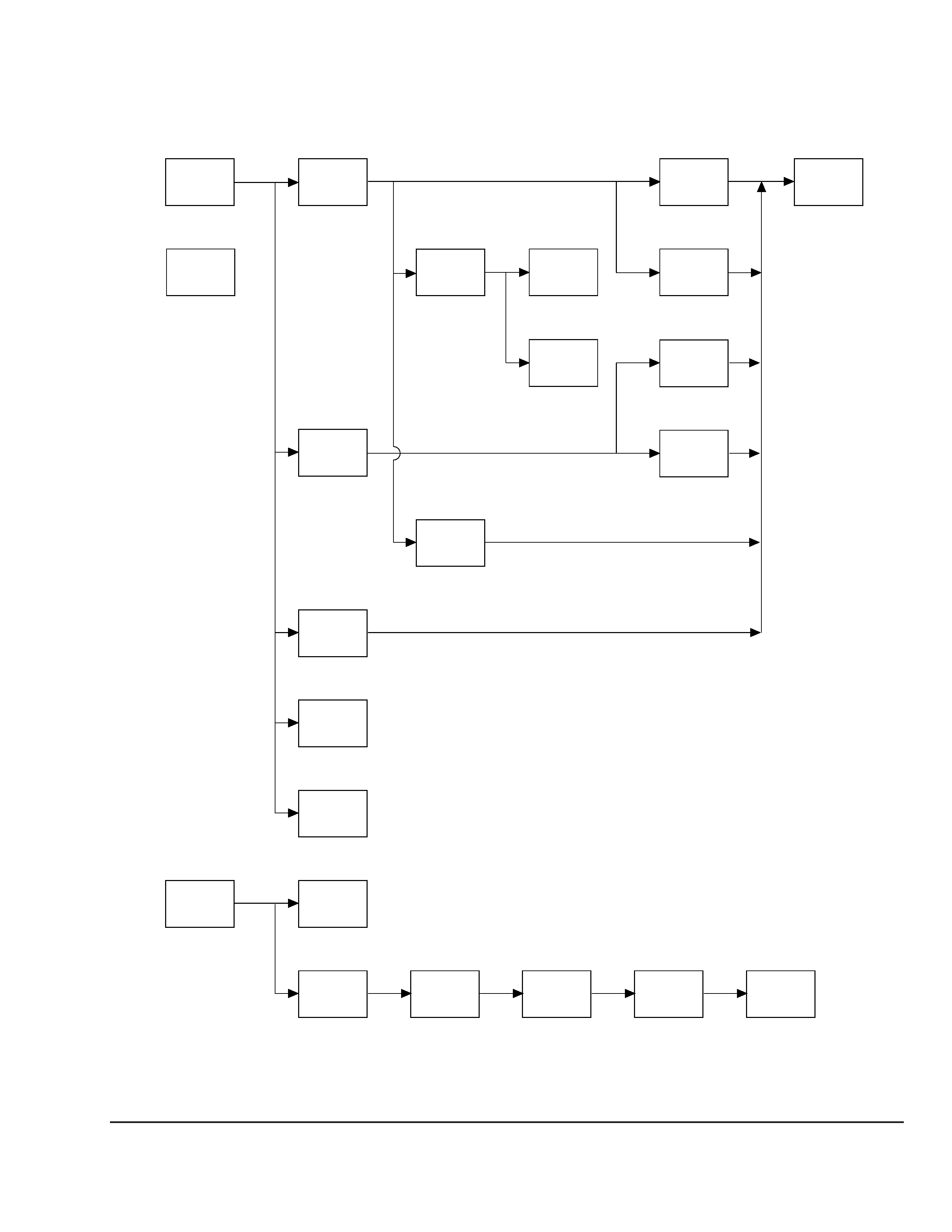
2-1.
FLOW CHART
·Ps-s denotes the page concerned.
·
HDD has a low resistance to vibration, requiring careful handling.
TOP
COVER
P2-2
· MAIN SECTION
· DISPLAY SECTION
P2-10
MEMORY
CARD
P2-2
HDD
P2-3
MODEM
CARD
(PCI/U)
MEMORY
CPU,
HEAT SINK
SWX-26A
MOUNT
LEX-14A
MOUNT
REAR
COVER
ARM
COVER
P2-9
LCD ASSY
P2-9
P2-4
P2-5
P2-6
P2-8
P2-8
IFX-94
MOUNT
P2-10
INVERTER
UNIT
P2-10
FRONT
COVER
P2-11
LCD
PANEL
P2-11
FDD
P2-3
DRIVE
SUPPORT
P2-8
DVD-
ROM
P2-3
DRIVE
HOLDER
P2-3
RIZER
CARD
P2-4
RIZER
SUPPORT
P2-4
POWER
SUPPLY
P2-7
MAIN
BOARD
P2-8
2-2
PCV-L620
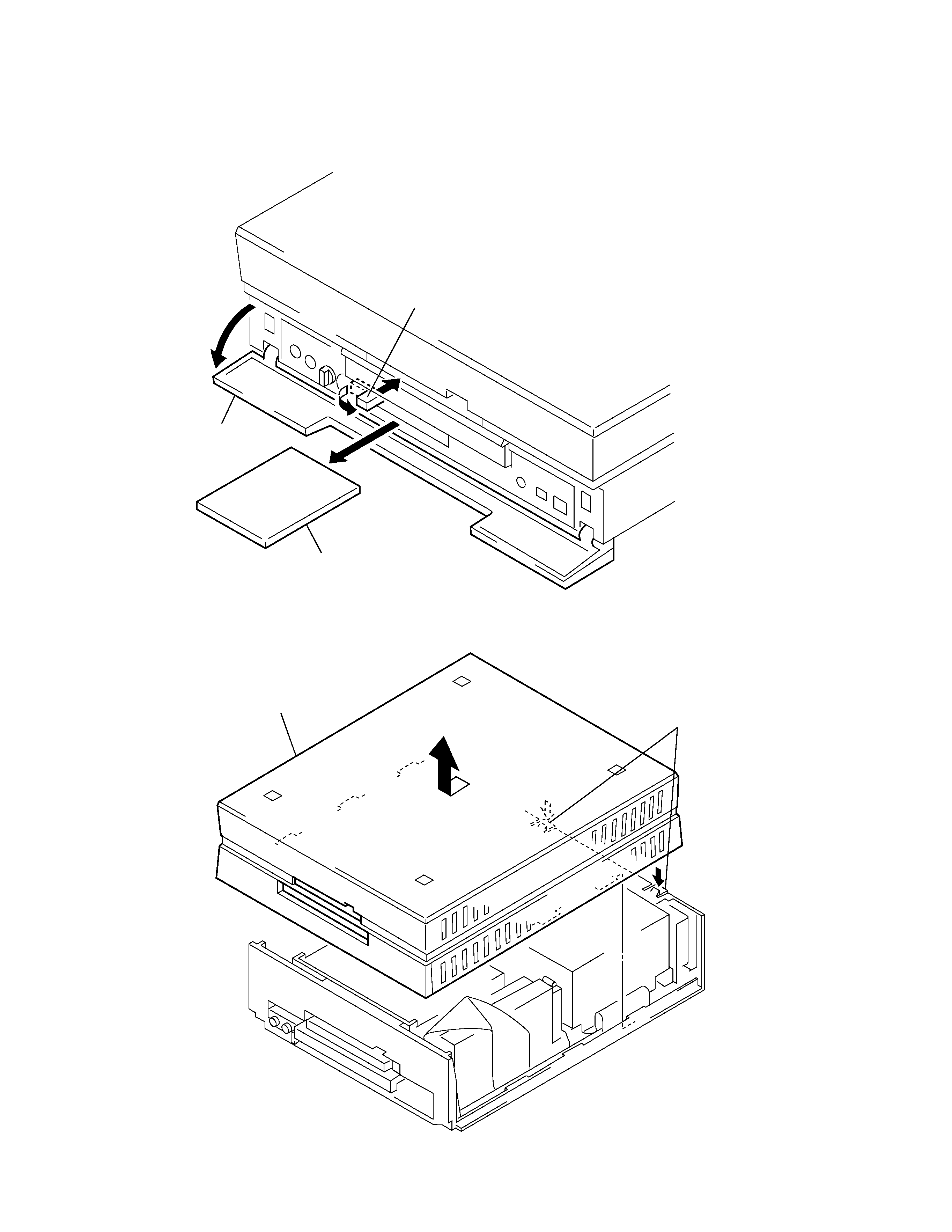
2-3.
TOP COVER
2-2.
MEMORY CARD
2
Erect the lever.
1
Open door ass'y.
3
memory card
2
Remove the top cover to
direction of the arrow B.
1
two claws
B