PCVA-15XD2
US Model
Canadian Model
SERVICE MANUAL
15 INCH TFT LCD DIGITAL DISPLAY
9-928-380-11
SPECIFICATIONS
LCD panel
Panel type: a-Si TFT Active Matrix
Picture size: 15 inch (38cm)
Picture element: 99.99%
Resolution
Horizontal: Max. 1024 dots
Vertical: Max. 768 lines
Power requirements
-- AC adapter
Input:
AC 100 240V/
1A/50 60Hz
Output: DC 12V/3A
-- LCD Display
Input:
DC12V/1.7A
Power consumption
Max. 36W (less than 3W in power
saving mode)
Dimensions (width/height/
depth)
Approx. 380
× 360 × 200 mm
(15
× 14 1/4 × 7 7/8 inches)
Mass
Approx. 5.5 kg (12 lb 2 oz)
Plug & Play
DDC1/DDC2B
Accessories
· LCD display
· AC adapter
· Power cord
· Warranty Card
· This instruction manual
Design and specifications are subject
to change without notice.

-- 2 --
PCVA-15XD2 (UC)
Information in this document is subject to change without notice.
Sony and VAIO are trademarks of Sony. Intel logo and Intel Inside
logo are registered trademarks of Intel Corporation. Pentium MMX
is a trademark of Intel Corporation. Microsoft, MS-DOS, Windows,
the Windows 95 and Windows 98 logo are trademarks of Microsoft
Corporation.
All other trademarks are trademarks or registered trademarks of
their respective owners. Other trademarks and trade names may be
used in this document to refer to the entitles claiming the marks and
names or their produces. Sony Corporation disclaims any proprietary
interest in trademarks and trade names other than its own.
Service and Inspection Precautions
1. Obey precautionary markings and instructions
Labels and stamps on the cabinet, chassis, and components identify areas
requiring special precautions. Be sure to observe these precautions, as well
as all precautions listed in the operating manual and other associated
documents.
2. Use designated parts only
The set's components possess important safety characteristics, such as
noncombustibility and the ability to tolerate large voltages. Be sure that
replacement parts possess the same safety characteristics as the originals.
Also remember that the 0 mark, which appears in circuit diagrams and
parts lists, denotes components that have particularly important safety
functions; be extra sure to use only the designated components.
3. Always follow the original design when mounting
parts and routing wires
The original layout includes various safety features, such as inclusion of
insulating materials (tubes and tape) and the mounting of parts above the
printer board. In addition, internal wiring has been routed and clamped so
as to keep it away from hot or high-voltage parts. When mounting parts or
routing wires, therefore, be sure to duplicate the original layout.
4. Inspect after completing service
After servicing, inspect to make sure that all screws, components, and wiring
have been returned to their original condition. Also check the area around
the repair location to ensure that repair work has caused no damage, and
confirm safety.
5. When replacing chip components...
Never reuse components. Also remember that the negative side of tantalum
capacitors is easily damaged by heat.
6. When handling flexible print boards...
· The temperature of the soldering-iron tip should be about 270C.
· Do not apply the tip more than three times to the same pattern.
· Handle patterns with care; never apply force.
Caution: Remember that hard disk drives are easily damaged by
vibration. Always handle with care.
Caution Markings for Lithium/Ion Battery - The following or similar
texts shall be provided on battery pack of equipment or in both the
operating and the service instructions.
CAUTION: Danger of explosion if battery is incorrectly replaced.
Replace only with the same or equivalent type recommended by
the manufacturer. Discard used batteries according to the
manufacturer's instructions.
CAUTION: The battery pack used in this device may present a fire
or chemical burn hazard if mistreated. Do not disassemble, heat
above 100°C (212°F) or incinerate.
Dispose of used battery promptly.
Keep away from children.
ATTENTION AU COMPOSANT AYANT RAPPORT
À LA SÉCURITÉ!
LES COMPOSANTS IDENTIFÉS PAR UNE MARQUE 0 SUR LES
DIAGRAMMES SCHÉMATIQUES ET LA LISTE DES PIÈCES SONT
CRITIQUES POUR LA SÉCURITÉ DE FONCTIONNEMENT. NE
REMPLACER CES COMPOSANTS QUE PAR DES PIÈSES SONY
DONT LES NUMÉROS SONT DONNÉS DANS CE MANUEL OU
DANS LES SUPPÉMENTS PUBLIÉS PAR SONY.
Confidential

-- 3 --
PCVA-15XD2 (UC)
Confidential
TABLE OF CONTENTS
1. OVERVIEW ······························································ 1-1
2. DISASSEMBLY
2-1. Flowchart ····································································· 2-1
2-2. Arm Rear Cover ··························································· 2-1
2-3. Arm Front Cover ·························································· 2-2
2-4. Rear Cover, Inverter Unit ············································· 2-3
2-5. LCD Ass'y (S), LEX-23 Board ···································· 2-4
2-6. IFX-105 Board ····························································· 2-5
2-7. Main Electrical Parts Location Diagram ······················ 2-5
3. SERVICE OVERVIEW
3-1. Service Tools ································································ 3-1
3-2. Procedure For Writing Edid Data ································ 3-1
3-3. Procedure For Writing Firmware ································· 3-1
4. BLOCK DIAGRAM
4-1. System Configuration ·················································· 4-1
4-2. Block Diagram ····························································· 4-1
5. FRAME HARNESS
5-1. Connector List ······························································ 5-1
5-2. Frame Harness Diagram ·············································· 5-2
6. EXPLODED VIEW
6-1. Exploded View And Parts List ····································· 6-1
6-2. Parts List (Accessories and Packing Materials) ··········· 6-2
1-1
PCVA-15XD2 (UC)
Confidential
(END)
SECTION 1
OVERVIEW
This section is extracted from
instruction manual (4-649-778-01).
7
US
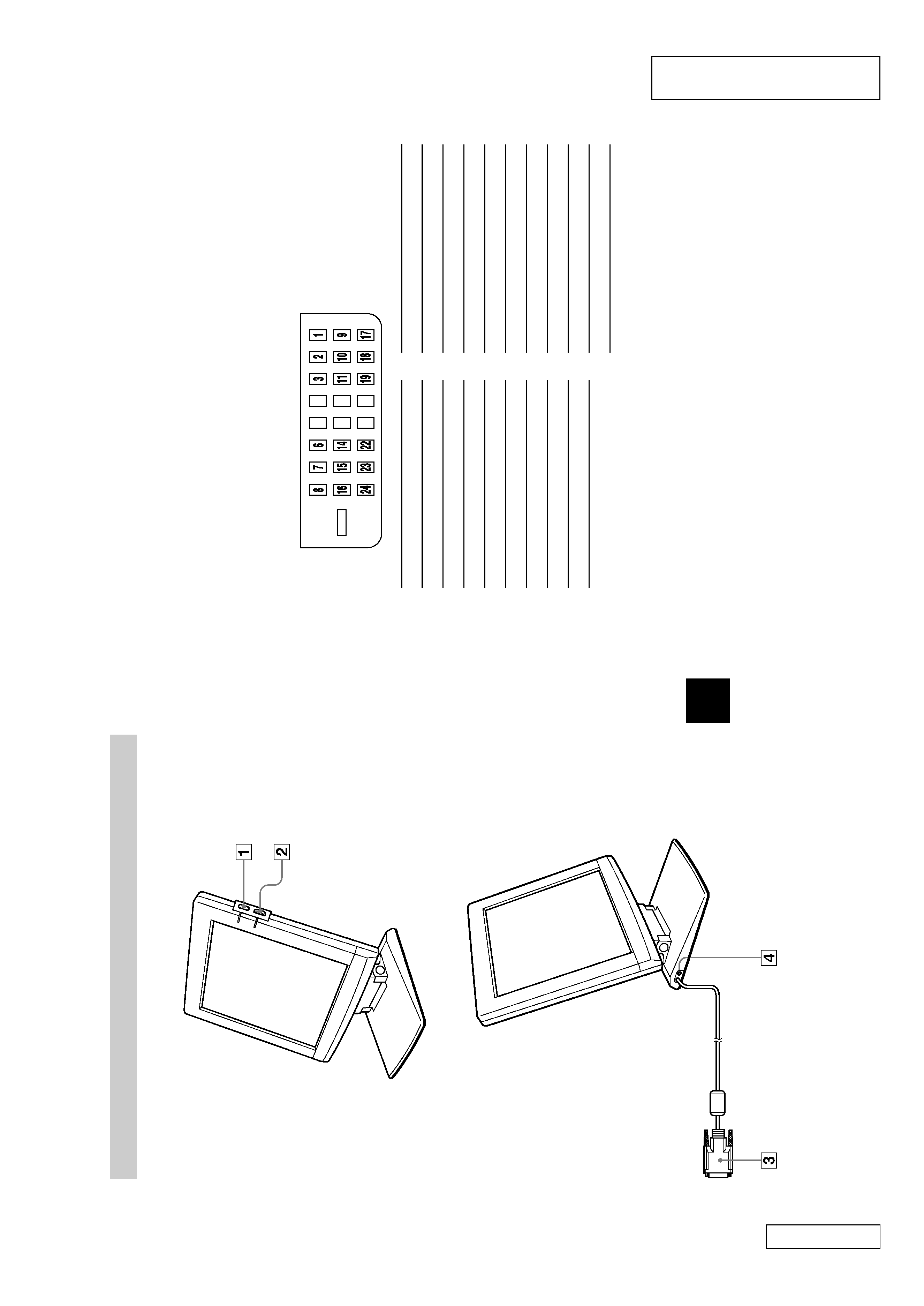
Identifying
par
ts
and
contr
ols
See
the
pages
in
par
entheses
for
further
details.
Right
Left
(Continued)
8
1
1
Power
switch
and
indicator
(pages
10,
12)
This
switch
turns
the
display
on
and
of
f.
The
indicator
lights
up
in
gr
een
when
the
display
is
turned
on.
The
indicator
lights
up
in
orange
when
the
display
is
in
power
saving
mode.
2
2
+/
Brightness
contr
ol
This
contr
ol
adjusts
the
brightness
of
the
scr
een.
3
DVI
video
input
connector
(page
9)
This
connector
inputs
digital
RGB
video
signals.
Pin
No.
Signal
1
T
MDS
Data
2
2
T
DMS
Data
2+
3
T
DMS
Data
2
Shield
6
DDC
Clock
7
DDC
Data
9
T
DMS
Data
1
10
TDMS
Data
1+
11
TDMS
Data
1
Shield
Pin
No.
Signal
14
+5V
Power
15
Gr
ound
(for
+5V)
16
Hot
Plug
Detect
17
TDMS
Data
0
18
TDMS
Data
0+
19
TDMS
Data
0
Shield
22
TDMS
Clock
Shield
23
TDMS
Clock+
24
TDMS
Clock
4
DC
IN
connector
(page
10)
This
connector
pr
ovides
DC
power
to
the
display
.Connect
the
AC
adapter
to
this
connector
.
2-1
PCVA-15XD2 (UC)
Confidential
SECTION 2
DISASSEMBLY
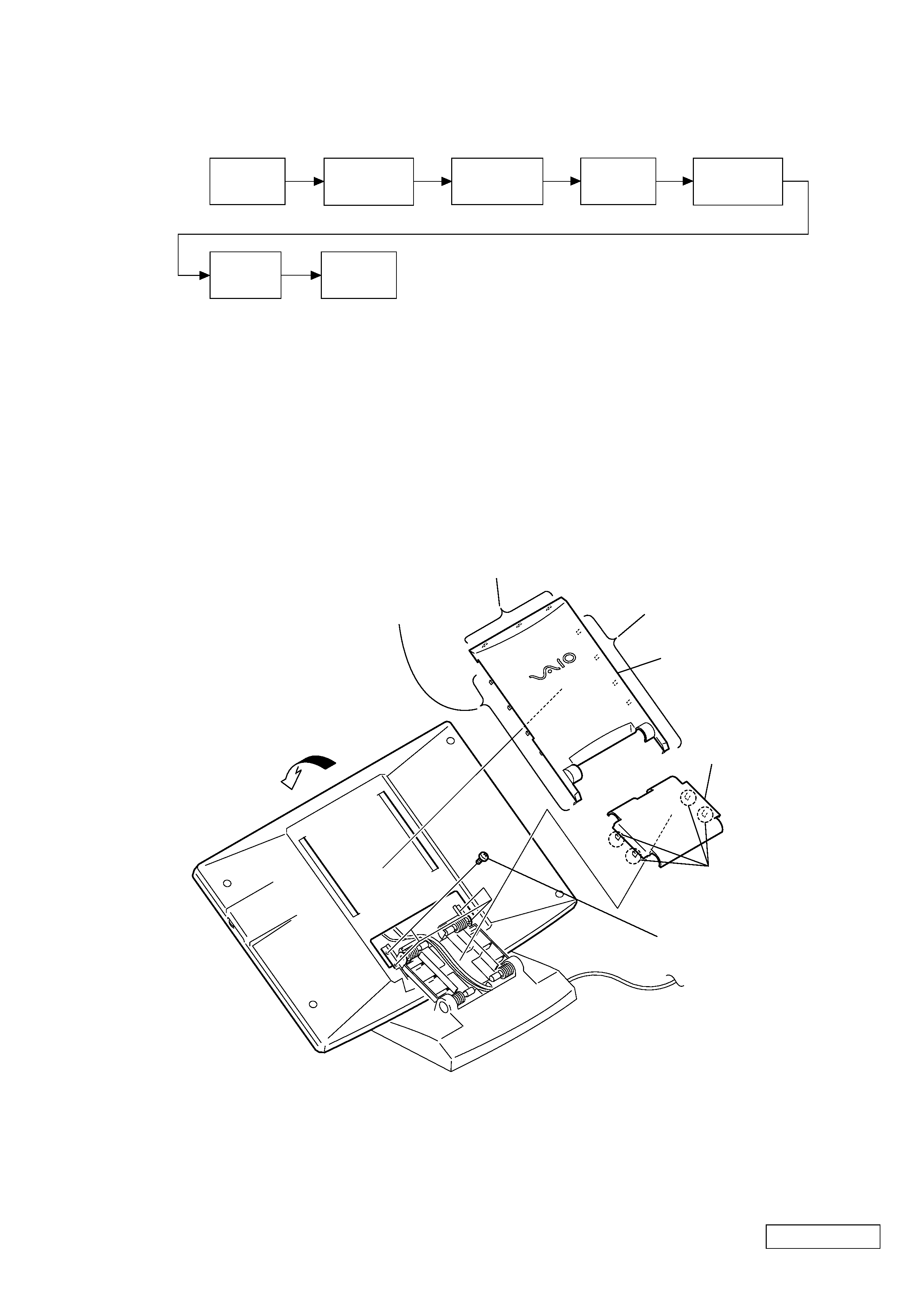
2-1. FLOWCHART
2-2. ARM REAR COVER
· P X-X means pages that appears in this manual.
ARM REAR
COVER
P2-1
ARM FRONT
COVER
P2-2
REAR COVER
P2-3
INVERTER
UNIT
P2-3
LCD ASS'Y (S)
P2-4
LEX-23
BOARD
P2-4
P2-5
IFX-105
BOARD
1
Slant the LCD ass'y (S)
in the direction of arrow A.
4
Five claws
4
Three claws
4
Five claws
2
Four claws
6
Four screws +PS (3
× 5)
5
VAIO rear cover
3
Arm rear cover
A