Ver 1.1 2002.01
9-960-914-12
Sony Corporation
2002A0500-1
Home Audio Company
C
2002.1
Published by Sony Engineering Corporation
DIGITAL AUDIO TAPE DECK
PCM-R700
SPECIFICATIONS
Remote commander RM-D757 (supplied)
Remote control system Infrared control
Power requirements
3 V DC, with two size-AA (R6) batteries
Dimensions
Approx 45
× 210 × 26 mm (w/h/d)
(113/16
× 83/
8
× 11/
16
inches)
Weight
Approx 100 g (3.5 oz) incl. batteries
Input connectors
Analog Input
Connector
Type
Input impedance Rated input level a)
ANALOG
Phono-
47 kilohms
12 dBs
(UNBALANCE) plug jack
ANALOG
XLR-3
10 kilohms
+4 dBs
(BALANCE)
(FEMALE)
or more
(factory setting)
(balanced)
Digital Input
Connector
Type
Input impedance Rated input level
AES/EBU
XLR-3
110 ohms
(FEMALE) (balanced)
COAXIAL
Phono-plug
75 ohms
0.5 Vp-p
jack
Recording section
Tape
Digital audio tape
Recording head
Rotary head
Recording time
Standard: 120 minutes
Long-play: 240 minutes
(DT-120)
Tape speed
Standard: 8.15 mm/s
Long-play: 4.075 mm/s
Drum rotation
Standard: 2,000 rpm
Long-play: 1,000 rpm
Error correction
Double-encoded Reed Solomon code
Tape section
Track pitch
13.6
µm (20.4 µm)
Sampling frequency
48 kHz, 44.1 kHz, 32kHz
Modulation system
8-10 modulation
Transfer rate
2.46 Mbit/sec
Number of channels
2 channels, stereo
D/A conversion
Standard: 16-bit linear
(quantization)
Long-play: 12-bit non-linear
General section
Power requirements
Where purchased
Power requirements
U.S.A./Canada
120 V AC, 60 Hz
Europe/U.K.
230 V AC, 50/60 Hz
Power consumption
34 W
Dimensions
Approx 482
× 145 × 355 mm (w/h/d)
(19
× 53/
4
× 14 inches)
(not including rack mount adaptor)
Weight
Approx 7.3 kg (16 Ib 2 oz)
Continued on next page
SERVICE MANUAL
Model Name Using Similar Mechanism
PCM-2800
Tape Transport Mechanism Type
DATM-58
US Model
Canadian Model
AEP Model
UK Model
2
Output connectors
Analog Output
Output
Rated
Load
Connector
Type
impedance
output
impedance
level a)
ANALOG
Phono-plug
1 kilohm
12 dBs 47 kilohms
(UNBALANCE) jack
ANALOG
XLR-3
100 ohms
+4 dBs
10 kilohms
(BALANCE)
(MALE)
(balanced)
(factory
or more
setting)
PHONES
Stereo phone-
100 ohms
0.36 mW 32 ohms
plug jack
Digital Output
Output
Rated
Load
Connector
Type
impedance
output
impedance
level
AES/EBU
XLR-3
35 ohms
110 ohms
(MALE)
(balanced)
COAXIAL
Phono-plug
75 ohms
0.5V p-p 75 ohms
jack
Variable range of analog (BALANCE) input/output reference level a)
+4 dBs to 12 dBs
Maximum analog (BALANCE) output level
+24 dBs
Remote switch connectors
DIN connector (8-pin, parallel)
Monaural minijack (serial)
Audio characteristics
Frequency response b)
Standard: 20-20,000 Hz (±0.5 dB)
Long-play: 20-14,500 Hz (±0.5 dB)
Signal-to-noise ratio b)
90 dB or more
(20 kHz LPF, A-weight filter ON)
Totalharmonic distortion b) Standard: 0.05% or less
Long-play: 0.3% or less
(1 kHz, Reference level a) 20 kHz LPF
ON)
Wow and flutter
Below measurable limit (± 0.001 % W.
PEAK)
a) The reference lebel corresponds to 20 dB on the peak level meters.
b) During analog input sith the SBM function off
Supplied accessories
AC power cord (1)
Remote commander (remote) RM-D757
(1)
Size-AA (R6) batteries (2)
Screws (M5
× 12) (4)
Decorative washers (4)
Operating instructions (1)
Warranty card (U.S.A. and Canadian
models only) (1)
Design and specifications are subject to change without notice.
CAUTION
Danger of explosion if battery is incorrectly replaced.
Replace only with the same or equivalent type recommended by the
manufacturer.
Discard used batteries according to the manufacturer's instructions.
ADVARSEL!
Lithiumbatteri-Eksplosionsfare ved fejlagtig håndtering.
Udskiftning må kun ske med batteri
af samme fabrikat og type.
Levér det brugte batteri tilbage til leverandøren.
ADVARSEL
Eksplosjonsfare ved feilaktig skifte av batteri.
Benytt samme batteritype eller en tilsvarende type
anbefalt av apparatfabrikanten.
Brukte batterier kasseres i henhold til fabrikantens
instruksjoner.
VARNING
Explosionsfara vid felaktigt batteribyte.
Använd samma batterityp eller en ekvivalent typ som
rekommenderas av apparattillverkaren.
Kassera använt batteri enligt fabrikantens instruktion.
VAROITUS
Paristo voi räjähtää, jos se on virheellisesti asennettu.
Vaihda paristo ainoastaan laitevalmistajan suosittelemaan tyyppiin.
Hävitä käytetty paristo valmistajan ohjeiden mukaisesti.
Flexible Circuit Board Repairing
· Keep the temperature of the soldering iron around 270 ° C during
repairing.
· Do not touch the soldering iron on the same conductor of the
circuit board (within 3 times).
· Be careful not to apply force on the conductor when soldering or
unsoldering .
Notes on chip component replacement
· Never reuse a disconnected chip component.
· Notice that the minus side of a tantalum capacitor may be dam-
aged by heat.
SERVICING NOTES
MODEL IDENTIFICATION
Model Number label (Printed in Back Panel)
MODEL NO. PCM-R700
DIGITAL AUDIO RECORDER
US, Canadian model : AC 120 V 60 Hz 34 W
AEP, UK Model
: AC 230 V
/ 50/60Hz 34 W
3
1.5 k
0.15
µF
AC
voltmeter
(0.75 V)
To Exposed Metal
Parts on Set
Earth Ground
SAFETY CHECK-OUT
After correcting the original service problem, perform the follow-
ing safety check before releasing the set to the customer:
Check the antenna terminals, metal trim, "metallized" knobs, screws,
and all other exposed metal parts for AC leakage. Check leakage as
described below.
LEAKAGE TEST
The AC leakage from any exposed metal part to earth ground and
from all exposed metal parts to any exposed metal part having a
return to chassis, must not exceed 0.5 mA (500 microampers). Leak-
age current can be measured by any one of three methods.
1. A commercial leakage tester, such as the Simpson 229 or RCA
WT-540A. Follow the manufacturers' instructions to use these
instruments.
2. A battery-operated AC milliammeter. The Data Precision 245
digital multimeter is suitable for this job.
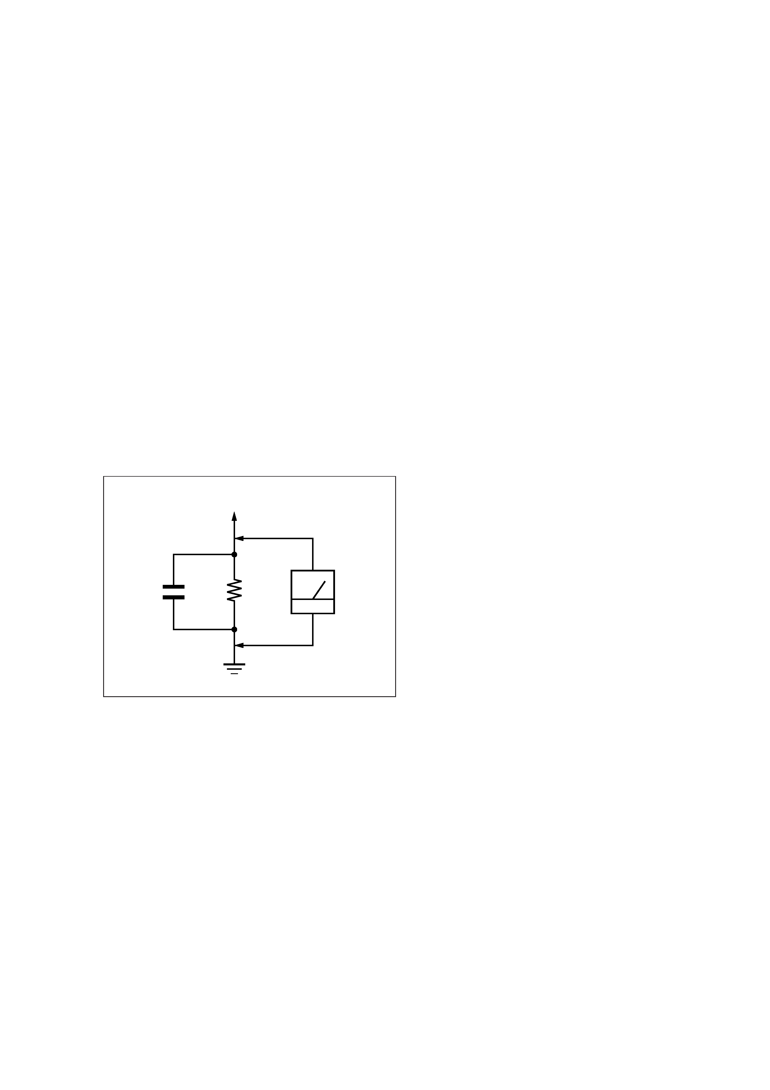
3. Measuring the voltage drop across a resistor by means of a VOM
or battery-operated AC voltmeter. The "limit" indication is 0.75
V, so analog meters must have an accurate low-voltage scale.
The Simpson 250 and Sanwa SH-63Trd are examples of a pas-
sive VOM that is suitable. Nearly all battery operated digital
multimeters that have a 2 V AC range are suitable. (See Fig. A)
Fig. A.
Using an AC voltmeter to check AC leakage.
TABLE OF CONTENTS
1.
GENERAL ..................................................................... 4
2.
DISASSEMBLY ............................................................ 18
3.
ADJUSTMENTS .......................................................... 22
4.
DIAGRAMS
4-1. Block Diagrams
Digital Audio Section .................................................. 29
Analog Audio Section .................................................. 31
System Control Section ............................................... 33
Power Section .............................................................. 35
4-2. Printed Wiring Board RF Section ................................ 40
4-3. Schematic Diagram RF Section ................................... 43
4-4. Printed Wiring Boards MD Section ............................. 46
4-5. Schematic Diagram MD Section ................................. 49
4-6. Printed Wiring Boards DIGITAL Section ................... 53
4-7. Schematic Diagram DIGITAL Section ........................ 57
4-8. Schematic Diagram AUDIO Section ........................... 61
4-9. Printed Wiring Boards AUDIO Section ....................... 65
4-10. Printed Wiring Boards DISPLAY Section ................... 69
4-11. Schematic Diagram DISPLAY Section ....................... 73
4-12. IC Pin Function Description .............................................. 76
5.
EXPLODED VIEWS ................................................... 88
6.
ELECTRICAL PARTS LIST .................................... 96
SAFETY-RELATED COMPONENT WARNING!!
COMPONENTS IDENTIFIED BY MARK
! OR DOTTED
LINE WITH MARK
! ON THE SCHEMATIC DIAGRAMS
AND IN THE PARTS LIST ARE CRITICAL TO SAFE
OPERATION. REPLACE THESE COMPONENTS WITH
SONY PARTS WHOSE PART NUMBERS APPEAR AS
SHOWN IN THIS MANUAL OR IN SUPPLEMENTS PUB-
LISHED BY SONY.
ATTENTION AU COMPOSANT AYANT RAPPORT
À LA SÉCURITÉ!
LES COMPOSANTS IDENTIFIÉS PAR UNE MARQUE
!
SUR LES DIAGRAMMES SCHÉMATIQUES ET LA LISTE
DES PIÈCES SONT CRITIQUES POUR LA SÉCURITÉ
DE FONCTIONNEMENT. NE REMPLACER CES COM-
POSANTS QUE PAR DES PIÈCES SONY DONT LES
NUMÉROS SONT DONNÉS DANS CE MANUEL OU
DANS LES SUPPLÉMENTS PUBLIÉS PAR SONY.
4
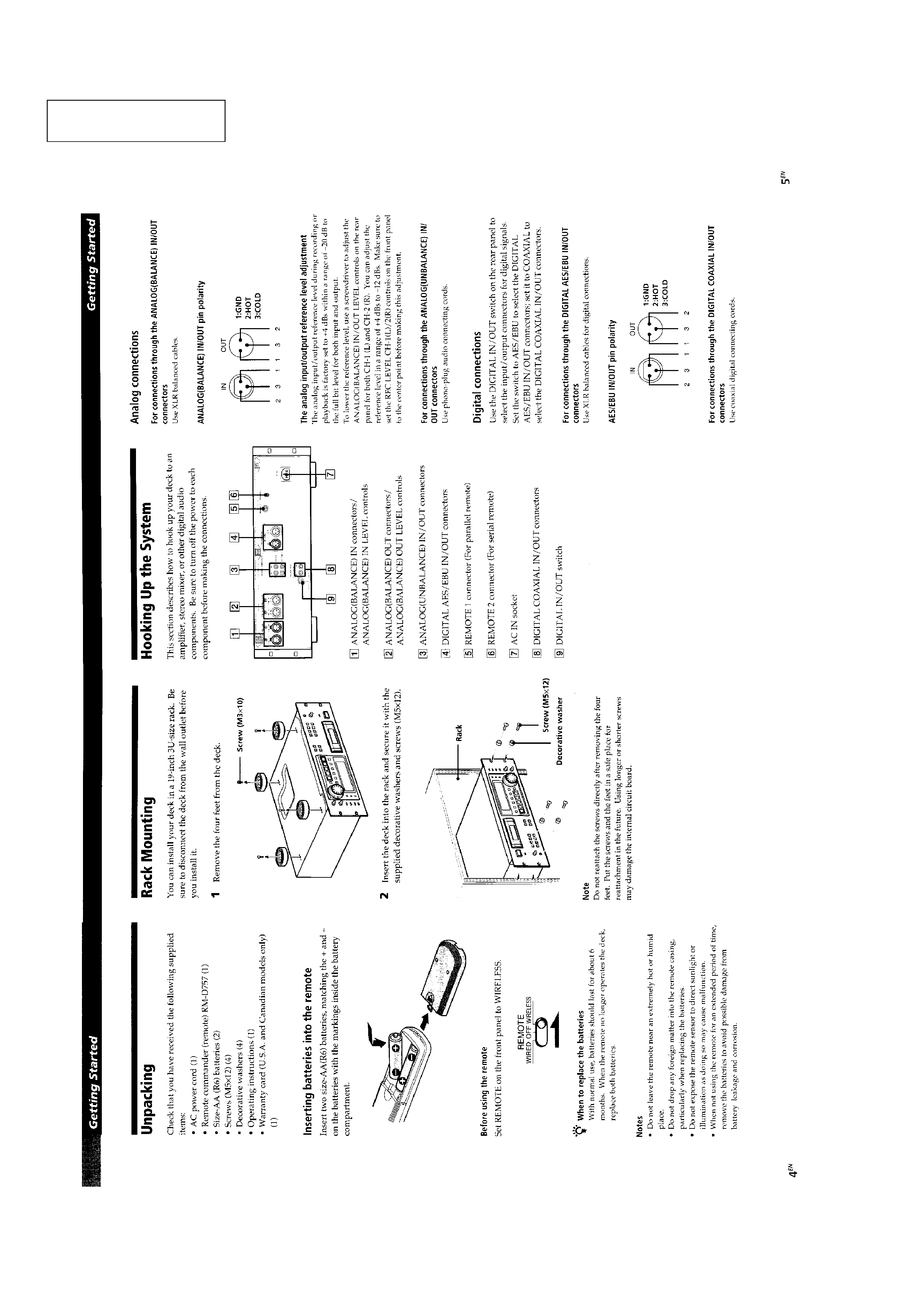
SECTION 1
GENERAL
This section is extracted
from instruction manual.
5