1
SERVICE MANUAL
PCM-R300
DIGITAL AUDIO RECORDER
US Model
Canadian Model
AEP Model
UK Model
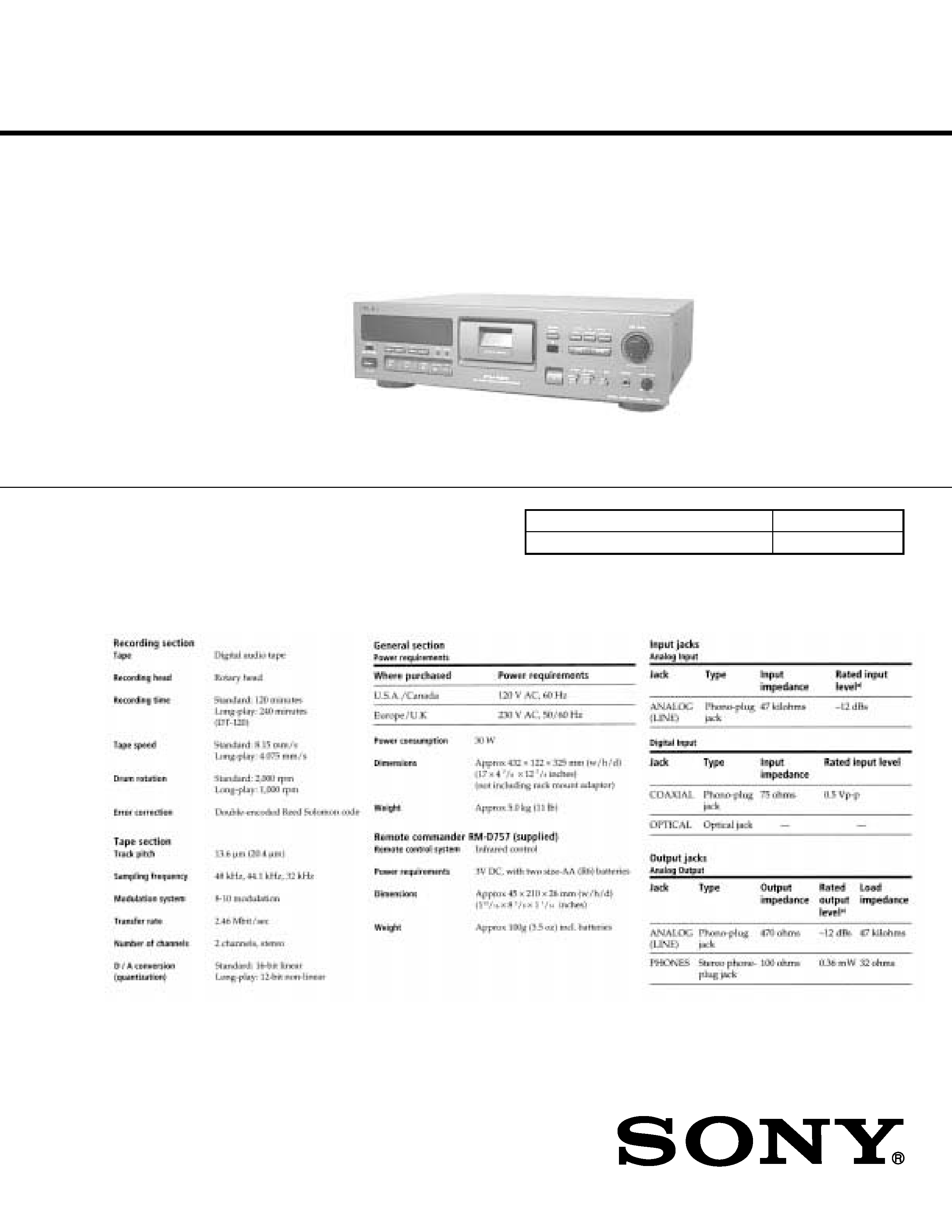
SPECIFICATIONS
Model Name Using Similar Mechanism
Tape Transport Mechanism Type
DTC-A6
DATM-110A
Continued on next page
Ver. 1.2 2006. 04
9-922-708-13
2006D02-1
© 2006.04
Sony Corporation
Home Audio Division
Published by Sony Techno Create Corporation
2
ATTENTION AU COMPOSANT AYANT RAPPORT
À LA SÉCURITÉ!!
LES COMPOSANTS IDENTIFIÉS PAR UNE MARQUE !SUR
LES DIAGRAMMES SCHÉMATIQUES ET LA LISTE DES
PIÈCES SONT CRITIQUES POUR LA SÉCURITÉ DE
FONCTIONNEMENT. NE REMPLACER CES COMPOSANTS
QUE PAR DES PIÈCES SONY DONT LES NUMÉROS
SONT DONNÉS DANS CE MANUEL OU DANS LES
SUPPLÉMENTS PUBLIÉS PAR SONY.
SAFETY-RELATED COMPONENT WARNING !!
COMPONENTS IDENTIFIED BY MARK ! OR DOTTED LINE
WITH MARK ! ON THE SCHEMATIC DIAGRAMS AND IN
THE PARTS LIST ARE CRITICAL TO SAFE OPERATION.
REPLACE THESE COMPONENTS WITH SONY PARTS
WHOSE PART NUMBERS APPEAR AS SHOWN IN THIS
MANUAL OR IN SUPPLEMENTS PUBLISHED BY SONY.
MODEL IDENTIFICATION
-- Back Panel --
Notes on chip component replacement
· Never reuse a disconnected chip component.
· Notice that the minus side of a tantalum capacitor may be
damaged by heat.
Parts No.
3-018-941-0
: US, Canadian model
3-018-941-1
: AEP, UK model
3
TABLE OF CONTENTS
1. SERVICING NOTE ........................................................... 4
2. GENERAL .......................................................................... 5
3. DISASSEMBLY
3-1. Case ..................................................................................... 14
3-2. Cassette Window ................................................................. 14
3-3. Mechanism Deck ................................................................ 14
3-4. Cassette Holder Assembly .................................................. 14
3-5. Cassette Compartment Motor (M901), Pulley,
Driving Gear and Slider ...................................................... 15
3-6. Drum Drive Board and Driving Chassis ............................. 15
3-7. Drum ................................................................................... 16
3-8. Capstan Motor (M902) ....................................................... 16
4. ADJUSTMENTS ............................................................ 17
5. DIAGRAMS
5-1. Circuit Boards Location ..................................................... 21
5-2. Block Diagrams
· MD Section ...................................................................... 22
· Main Section .................................................................... 23
· Display/Power Section ..................................................... 25
5-3. Schematic Diagram -- MD Section -- .............................. 26
5-4. Printed Wiring Board -- MD Section -- ........................... 29
5-5. Printed Wiring Board -- Main Section -- ......................... 32
5-6. Schematic Diagram -- Main Section (1/3) -- ................... 35
5-7. Schematic Diagram -- Main Section (2/3) -- ................... 38
5-8. Schematic Diagram -- Main Section (3/3) -- ................... 41
5-9. Printed Wiring Board -- Dispaly Section -- ..................... 44
5-10. Schematic Diagram -- Display Section -- ...................... 47
5-11. IC Block Diagrams ........................................................... 49
5-12. IC Pin Functions ............................................................... 53
6. EXPLODED VIEWS
6-1. Case and Back Panel Section .............................................. 59
6-2. Front panel Section ............................................................. 60
6-3. Chassis Section ................................................................... 61
6-4. Cassette Compartment Section ........................................... 62
6-5. Chassis L/R Section ............................................................ 63
6-6. Mechanism Section-1 (DATM-110A) ................................ 64
6-7. Mechanism Section-2 (DATM-110A) ................................ 65
6-8. Mechanism Section-3 (DATM-110A) ................................ 66
7. ELECTRICAL PARTS LIST ........................................ 67
SAFETY CHECK-OUT
After correcting the original service problem, perform the following
safety checks before releasing the set to the customer:
Check the antenna terminals, metal trim, "metallized" knobs, screws,
and all other exposed metal parts for AC leakage. Check leakage as
described below.
LEAKAGE
The AC leakage from any exposed metal part to earth Ground and
from all exposed metal parts to any exposed metal part having a re-
turn to chassis, must not exceed 0.5 mA (500 microampers). Leak-
age current can be measured by any one of three methods.
1. A commercial leakage tester, such as the Simpson 229 or RCA
WT-540A. Follow the manufacturers' instructions to use these
instruments.
2. A battery-operated AC milliammeter. The Data Precision 245 digi-
tal multimeter is suitable for this job.
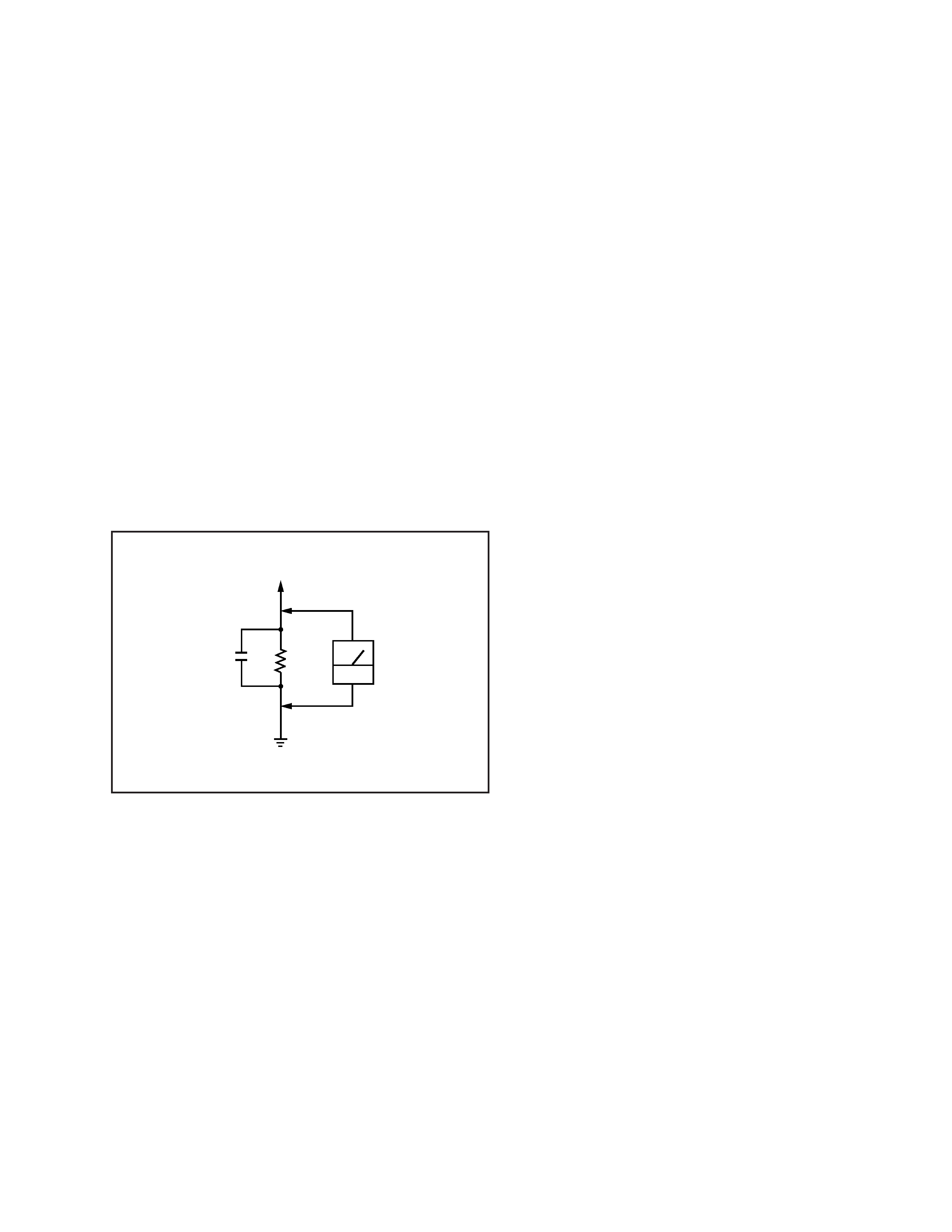
3. Measuring the voltage drop across a resistor by means of a VOM
or battery-operated AC voltmeter. The "limit" indication is 0.75
V, so analog meters must have an accurate low-voltage scale. The
Simpson 250 and Sanwa SH-63Trd are examples of a passive VOM
that is suitable. Nearly all battery operated digital multimeters
that have a 2V AC range are suitable. (See Fig. A)
Fig. A. Using an AC voltmeter to check AC leakage.
AC
voltmeter
(0.75V)
1.5k
0.15
µF
Earth Ground
To Exposed Metal
Parts on Set
4
SECTION 1
SERVICING NOTE
Fluorescent indicator tube lit, key check mode
The Fluorescent indicator tubes and keys can be checked in this test
mode.
Settings: INPUT switch
: Center click
ID MODE switch
: Center click
REC MODE switch : Center click
NOTE:The method differs for when the remote commander provided
is used or not.
Method:
1. Disconnect the AC plug from the outlet, and short-circuit the TP
(TEST) of the display board and ground.
2. Connect the AC plug to the outlet, and turn on the power to start
the check.
Flow:
The left and right segments of the Fluorescent indicator tubes and
level meters light up, and the grids light up in order from the right
side.
The level meters go off one by one.
Operate the remote commander for DAT in this state.
Pressing the
6button will
display "NEXT KEY" and
set the key check mode.
Pressing a button on the panel or switching a switch will light up the
level meters one by one.
When all buttons and switches have been operated, all the level meters
will be lit and "KEY OK" will be displayed instantaneously.
"TEST END" is displayed and the test mode is ended.
· To reset the test mode, turn the power off and disconnect the wire
shorting TP (TEST) and ground.
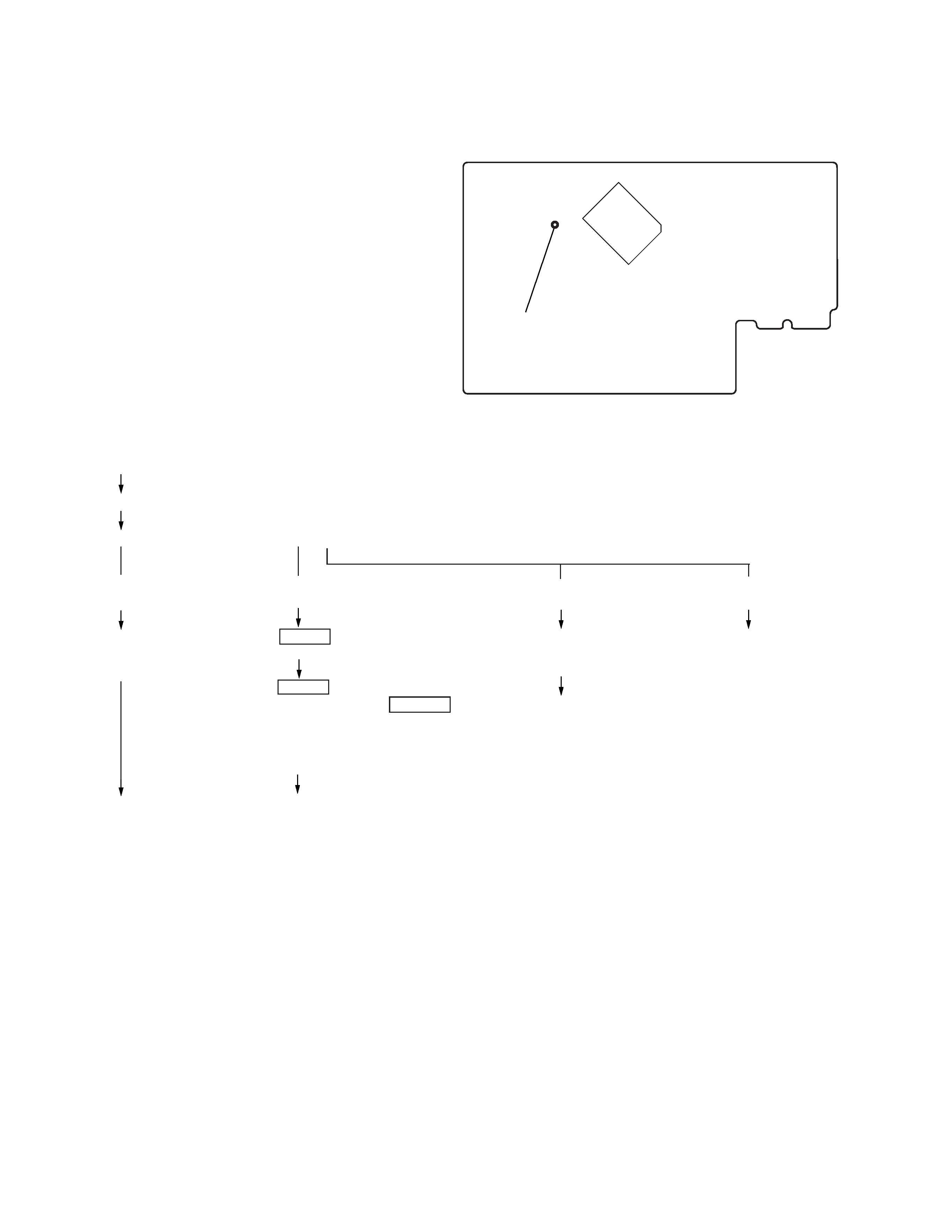
Test mode
IC801
TP (TEST)
Pressing the
4 button
will turn off the segments
on the left and right sides.
Pressing the
7button will
display "TEST END" and
end the test mode.
· Part Location
[DISPLAY BOARD] (Conductor side)
(If the remote commander
is not used)
Press the pSTOP button.
"NEXT RMC" will be displayed.
Press the "PLAY button for more than
1 second, and then press the PPAUSE
button.
"NEXT KEY" will be displayed and the
key check mode will be set.
(If the remote commander
is used)
(If the remote commander
is used)
(If the remote commander
is not used)
To end the test mode,
disconnect the AC plug
from the outlet.
5
SECTION 2
GENERAL
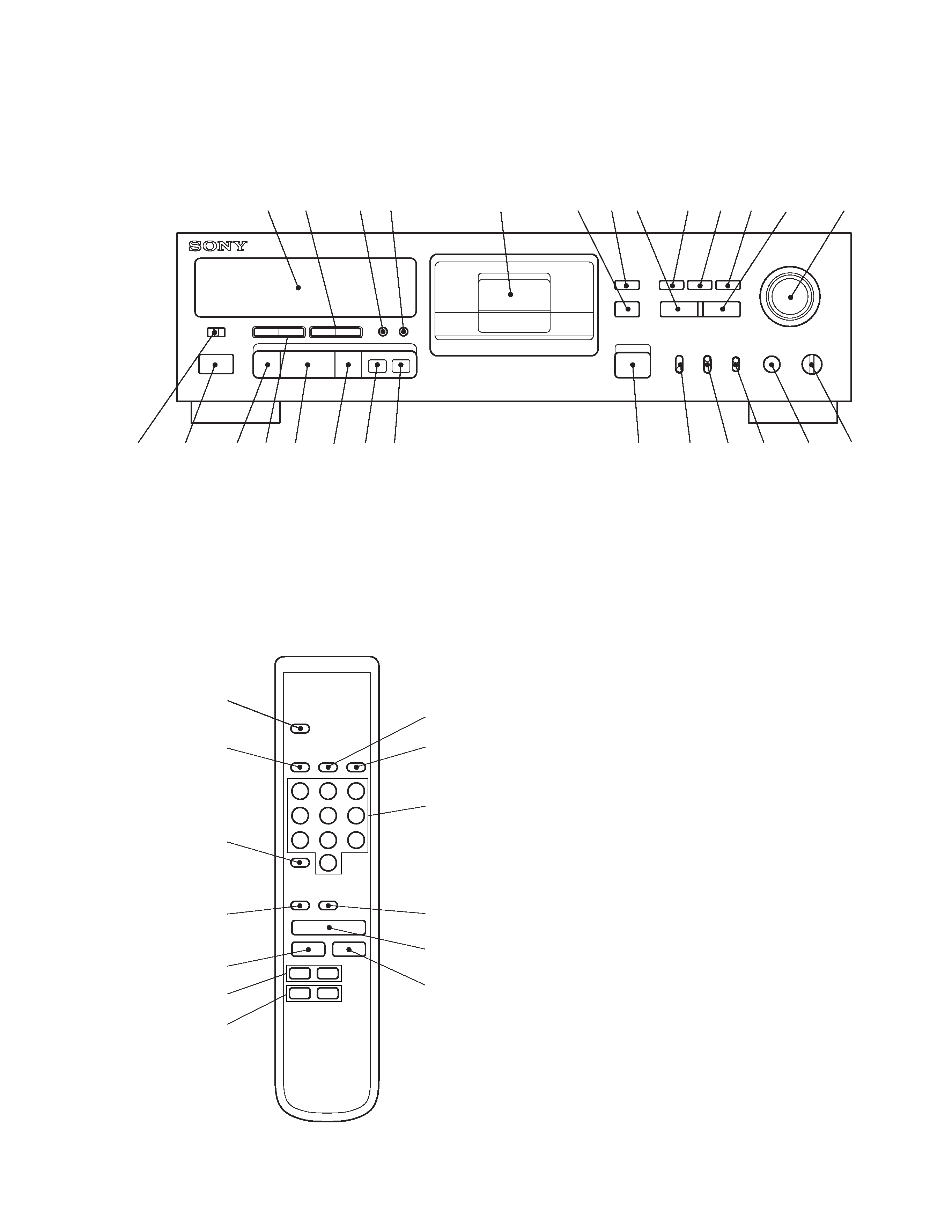
Location of Parts and Controls
Front panel
1
Display window
2
0/) (REW/FF), DATA buttons
3
MODE, MENU button
4
RESET, ENTER button
5
Cassette holder
6
Remote sensor
7
MARGIN RESET button
8
WRITE button
9
START ID AUTO button
10 START ID RENUMBER button
11 START ID REHEARSAL button
12 ERASE button
13 REC LEVEL control
14 PHONE LEVEL control
15 PHONES jack
16 SBM switch
17 REC MODE switch
18 ID MODE switch
19 6 OPEN / CLOSE button
20 r REC button
21 R REC MUTE button
22 P PAUSE button
23 ( PLAY button
24 =/+ AMS, SELECT buttons
25 p STOP button
26 POWER button
27 INPUT switch
28 COUNTER MODE button
29 COUNTER RESET button
30 Numeric buttons
31 CLEAR button
32 REPEAT button
Remote commander (RM-D757)
27
26
25
24 23
22 21 20
19
18
17
16
15
14
13
12
11
10
9
8
7
6
5
4
3
2
1
19
32
31
21
25
24
2
22
23
20
30
29
28