
file:///C|/Documents%20and%20Settings/bob/My%20Documents/manualdirectory.htm
This file was downloaded and provided FREE OF CHARGE
from the ManualDirectory community.
You can find many free to download Service Manuals & Schematics at
http://www.manualdirectory.co.uk
file:///C|/Documents%20and%20Settings/bob/My%20Documents/manualdirectory.htm01/04/2007 01:34:00
PCG-Z505GA/Z505GA
T
(I)
9-872-142-41
2000K1605-1
®
Sony Corporation
Information Technology Company
9-872-142-41
PCG-Z505GT/Z505GAT (I)
English
2000K1605-1
Printed in U.S.A.
© 2000 Sony Corporation
PNC Planning & Control Dept. [SODP]
This manual and the constituent data may not be
replicated, copied nor reprinted in whole or in part
without prior written authorization of Sony Corporation.
Conf
idential
PCG-Z505GA/Z505GAT
International Model
SERVICE MANUAL
NOTEBOOK COMPUTER
9-872-142-41
S400
Illust : PCG-Z505GAT
-- 2 --
PCG-Z505GA/Z505GAT (I)
Information in this document is subject to change without notice.
Sony and VAIO are trademarks of Sony. Intel logo and Intel Inside
logo are registered trademarks of Intel Corporation. Pentium MMX
is a trademark of Intel Corporation. Microsoft, MS-DOS, Windows,
the Windows 95 and Windows 98 logo are trademarks of Microsoft
Corporation.
All other trademarks are trademarks or registered trademarks of
their respective owners. Other trademarks and trade names may be
used in this document to refer to the entities claiming the marks and
names or their products. Sony Corporation disclaims any proprietary
interest in trademarks and trade names other than its own.
Service and Inspection Precautions
1. Obey precautionary markings and instructions
Labels and stamps on the cabinet, chassis, and components identify areas
requiring special precautions. Be sure to observe these precautions, as well
as all precautions listed in the operating manual and other associated
documents.
2. Use designated parts only
The set's components possess important safety characteristics, such as
noncombustibility and the ability to tolerate large voltages. Be sure that
replacement parts possess the same safety characteristics as the originals.
Also remember that the 0 mark, which appears in circuit diagrams and
parts lists, denotes components that have particularly important safety
functions; be certain to use only the designated components.
3. Always follow the original design when mounting
parts and routing wires
The original layout includes various safety features, such as inclusion of
insulating materials (tubes and tape) and the mounting of parts above the
printer board. In addition, internal wiring has been routed and clamped so
as to keep it away from hot or high-voltage parts. When mounting parts or
routing wires, therefore, be sure to duplicate the original layout.
4. Inspect after completing service
After servicing, inspect to make sure that all screws, components, and wiring
have been returned to their original condition. Also check the area around
the repair location to ensure that repair work has caused no damage, and
confirm safety.
5. When replacing chip components...
Never reuse components. Also remember that the negative side of tantalum
capacitors is easily damaged by heat.
6. When handling flexible print boards...
· The temperature of the soldering-iron tip should be about 270
°C.
· Do not apply the tip more than three times to the same pattern.
· Handle patterns with care; never apply force.
Caution: Remember that hard disk drives are easily damaged by
vibration. Always handle with care.
Caution Markings for Lithium/Ion Battery - The following or similar
texts shall be provided on battery pack of equipment or in both the
operating and the service instructions.
CAUTION: Danger of explosion if battery is incorrectly replaced.
Replace only with the same or equivalent type recommended by
the manufacturer. Discard used batteries according to the
manufacturer's instructions.
CAUTION: The battery pack used in this device may present a fire
or chemical burn hazard if mistreated. Do not disassemble, heat
above 100
°C (212°F) or incinerate.
Dispose of used battery promptly.
Keep away from children.
CAUTION: Changing the back up battery.
· Overcharging, short circuiting, reverse charging, multilation or
incineration of the cells must be avoided to prevent one or more
of the following occurrences; release of toxic materials, release of
hydrogen and/or oxygen gas, rise in surface temperature.
· If a cell has leaked or vented, it should be replaced immediately.
Do not touch it without protection.
ATTENTION AU COMPOSANT AYANT RAPPORT
À LA SÉCURITÉ!
LES COMPOSANTS IDENTIFÉS PAR UNE MARQUE 0 SUR LES
DIAGRAMMES SCHÉMATIQUES ET LA LISTE DES PIÈCES SONT
CRITIQUES POUR LA SÉCURITÉ DE FONCTIONNEMENT. NE
REMPLACER CES COMPOSANTS QUE PAR DES PIÈSES SONY
DONT LES NUMÉROS SONT DONNÉS DANS CE MANUEL OU
DANS LES SUPPÉMENTS PUBLIÉS PAR SONY.
Confidential

TABLE OF CONTENTS
Section
Title
Page
PCG-Z505GA
/Z505GAT (I)
Confidential
-- 3 --
CHAPTER 1. REMOVAL
1-1. Flowchart ......................................................................... 1-1
1-2. Main Electrical Parts Location Diagram ......................... 1-1
1-3. Removal ........................................................................... 1-2
1. Keyboard Unit .................................................................. 1-2
2. Palm Rest Assembly ........................................................ 1-2
3. SWX-47 Board, Touch Pad, and Speaker Unit ................ 1-3
4. Modular Jack, Harness (DC Jack), and RO-38 Board ..... 1-3
5. HDD, and SWX-48 Board ............................................... 1-4
6. DC Fan ............................................................................. 1-4
7. IFX-122 Board, CNX-106 Board,
and PC Card Connector ................................................... 1-5
8. Main Board Assembly (MBX-42 Board),
IFX-123 Board, V/L Rechargeable Battery,
and Memory Module ....................................................... 1-5
9. Display Assembly ............................................................ 1-6
10. Bezel Housing Assembly ................................................. 1-6
11. LEX-20 Board, Inverter Unit, and LCD Unit .................. 1-7
(to 1-7)
CHAPTER 2. SELF DIAGNOSTICS
2-1. Note .................................................................................. 2-1
2-2. Necessary Tools ............................................................... 2-1
2-3. Starting up the Service Diagnostics ................................. 2-1
2-4. Outline of Service Diagnostics Functions ....................... 2-2
2-5. Inspecting Windows ......................................................... 2-5
(to 2-5)
CHAPTER 3. BLOCK DIAGRAM ............................... 3-1
(to 3-2)
CHAPTER 4. FRAME HARNESS DIAGRAM ........ 4-1
(to 4-2)
CHAPTER 5. EXPLODED VIEWS AND
PARTS LIST
5-1. Main Section .................................................................... 5-1
5-2. LCD Section Made by AC ......................................... 5-3
(to 5-4)
CHAPTER 1. SPECIFICATIONS................................. 1-1
APPENDIX
CHAPTER 2. OVERVIEW
2-1. Locating Controls and Connectors .................................. 2-1
CHAPTER 3. SERVICE INFORMATION
3-1. Install Procedure after the Hard Disk is Replaced .......... 3-1
1-1
PCG-Z505GA/A505GA T (I)
Confidential
CHAPTER 1.
REMOVAL
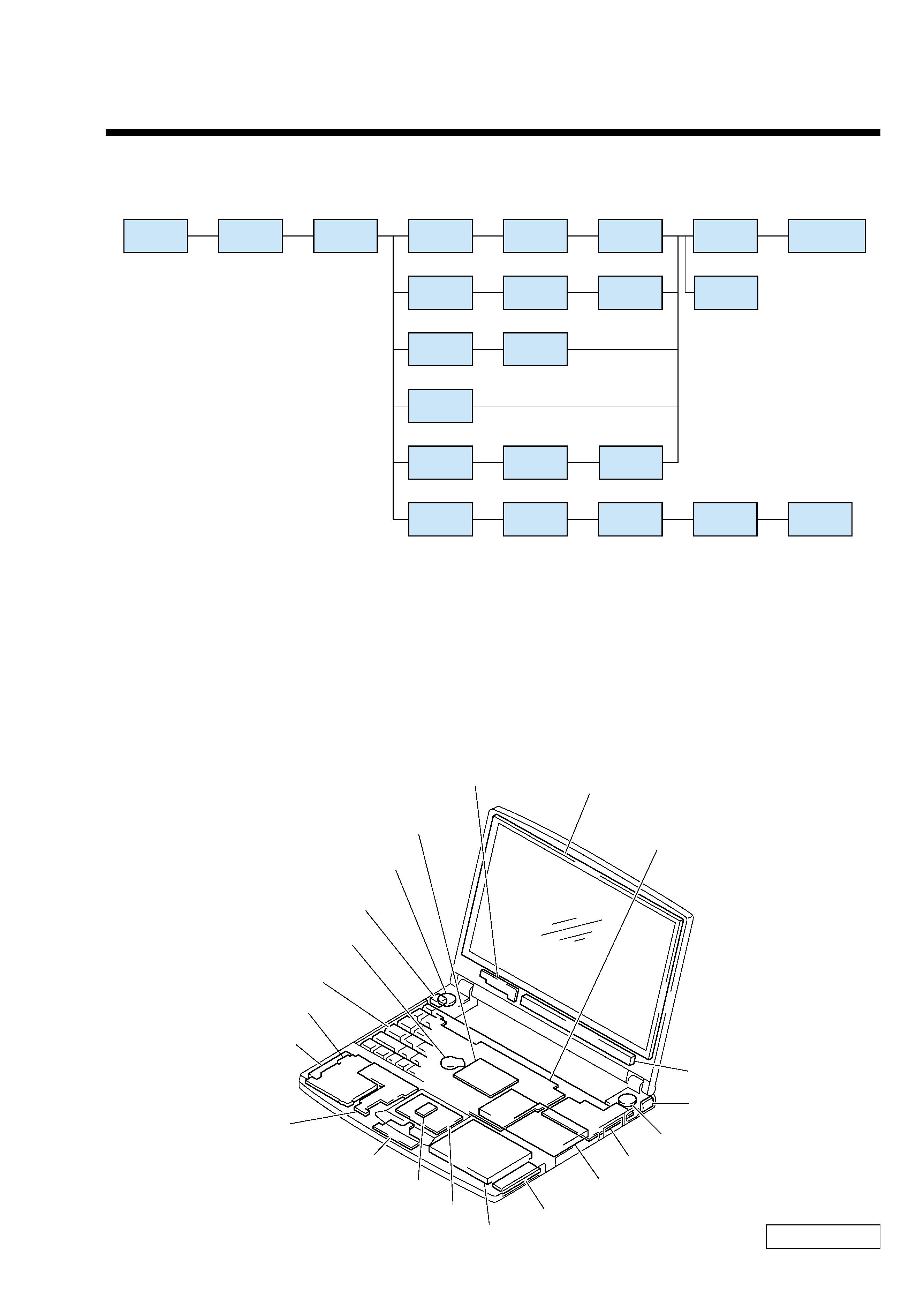
1-1. Flowchart
· P XX denotes the page which corresponds with the item referenced.
· Remember that hard disk drives are easily damaged by vibration. Always handle with care.
· When the thermal sheet (Part No. 4-645-921-01) of the computer reaches a certain temperature, it becomes soft, which
increases the contact. Therefore, it may be difficult to disassemble the fan at room temperature. In this case, use a dryer or
soldering iron to heat up the plate metal contacting the fan.
In addition, replace the old thermal sheet with a new one, to maintain the heating performance.
1-2. Main Electrical Parts Location Diagram
POWER
OFF
P1-2
KEYBOARD
UNIT
P1-2
PALM REST
ASSY
P1-3
P1-3
P1-4
P1-4
P1-5
P1-6
SWX-47
BOARD
MODULAR
JACK
SWX-48
BOARD
DC FAN
IFX-122
BOARD
DISPLAY
ASSY
P1-3
P1-3
P1-7
SPEAKER
UNIT
LEX-20
BOARD
RO-38
BOARD
P1-5
P1-7
V/L
RECHARGEABLE
BATTERY
LCD
UNIT
P1-5
P1-7
MAIN BOARD
ASSY
INVERTER
UNIT
P1-3
P1-3
P1-4
P1-6
P1-5
TOUCH PAD
BEZEL
HOUSING
ASSY
HARNESS
(DC JACK)
CNX-106
BOARD
HDD
P1-5
P1-5
PC CARD
CONNECTOR
IFX-123
BOARD
HDD
SWX-47 Board
IFX-122 Board
CNX-106 Board
RO-38 Board
Touch Pad
SWX-48 Board
DC Fan
Main Board Assy (MBX-42 Board)
Speaker Unit
Modular Jack
(Z505GAT Model)
Inverter Unit
LCD Unit
LEX-20 Board
PC Card Connector
V/L Rechargeable Battery
Keyboard Unit
Harness (DC Jack)
Speaker Unit
Memory Module
IFX-123 Board