
SPECIFICATIONS
F99
Picture tube
Video image area
Resolution
Standard image
area
Input signal
Video
Sync
0.24 mm (center) -0.25mm (edge)
aperture grill pitch
19 inches measured diagonally
90-degree deflection
(17.99" maximum viewing image)
Approx. 365 X 274 mm (w/h)
(143/8 x 104/5 inches)
Horizontal: Max. 1920 dots
Vertical: Max. 1440 lines
Approx. 352 x 264 mm (w/h)
(137/8 x 102/5 inches)
Analog RGB (75 ohms typical)
0.7 Vp-p, Positive
Separate Horizontal and Vertical
TTL level, Positive or Negative
Video Composite (Sync on Green)
0.3 Vp-p
Power Consumption
Maximum
Nominal
Deflection frequency
AC input voltage/current
Dimensions
Mass
CHASSIS
140 W, 478 BTU/h
100 W, 341BTU/h
Horizontal: 30 to 107 KHz (automatic)
Vertical: 48 to120 Hz (automatic)
100 to 120 V, 50/60 Hz,
1.8A (RMS) at 100VAC
220 to 240V, 50/60Hz,
1.0A (RMS) at 240 VAC
449 x 475 x 462 mm (w/h/d)
(172/3 x 187/10 x 181/5 inches)
Approx. 26.0 kg (57 lb 5 oz)
SERVICE MANUAL
Design and specifications are subject to change without notice.
P900
COLOR MONITOR
P900
US Model
Canadian Model
AEP Model
AUS Model
Japan Model
N. Hemisphere Model
UK Model
Chassis No. SCC-L30M-A
861 Front.p65
09/08/1999, 1:20 PM
1
-- 2 --
P900
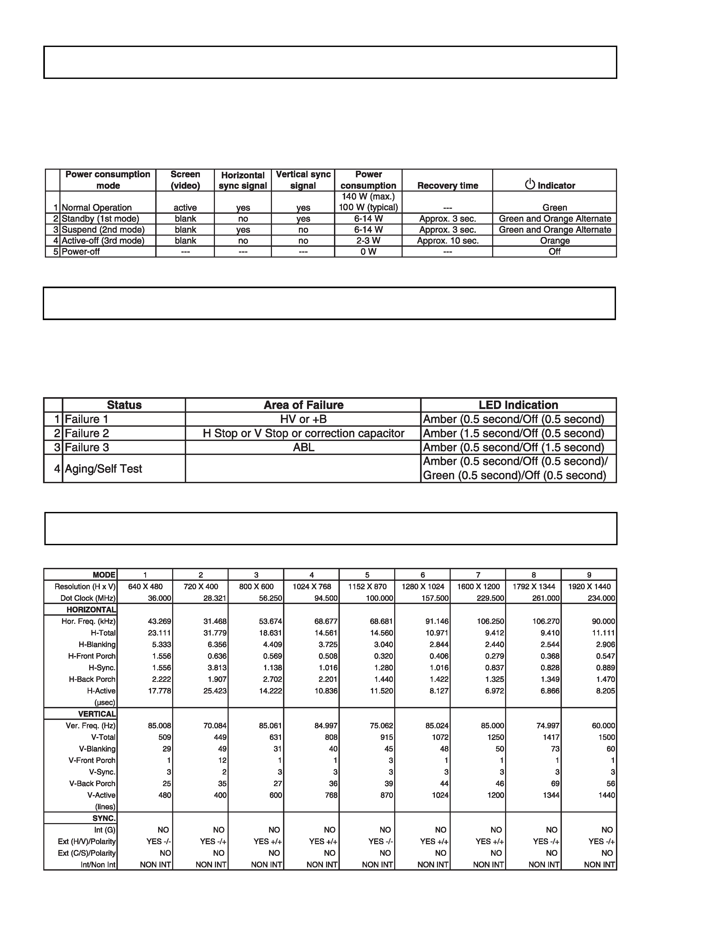
If you have VESA's DPMS compliance display card or software installed in your PC, the monitor can automatically reduce
its power consumption when not in use. If input from keyboard, mouse, or other input devices is detected, the monitor
will automatically "wake up." The following table shows the power consumption and signaling of this automatic power
saving feature.
When a failure occurs, the STANDBY/TIMER lamp will flash a set number of times to indicate the possible cause of the
problem. If there is more than one error, the lamp will identify the first of the problem areas.
SELF DIAGNOSTIC FUNCTION
POWER MANAGEMENT MODES
TIMING SPECIFICATIONS
-- 3 --
P900
1.5 k
0.15 µF
AC
Voltmeter
(0.75 V)
To Exposed Metal
Parts on Set
Earth Ground
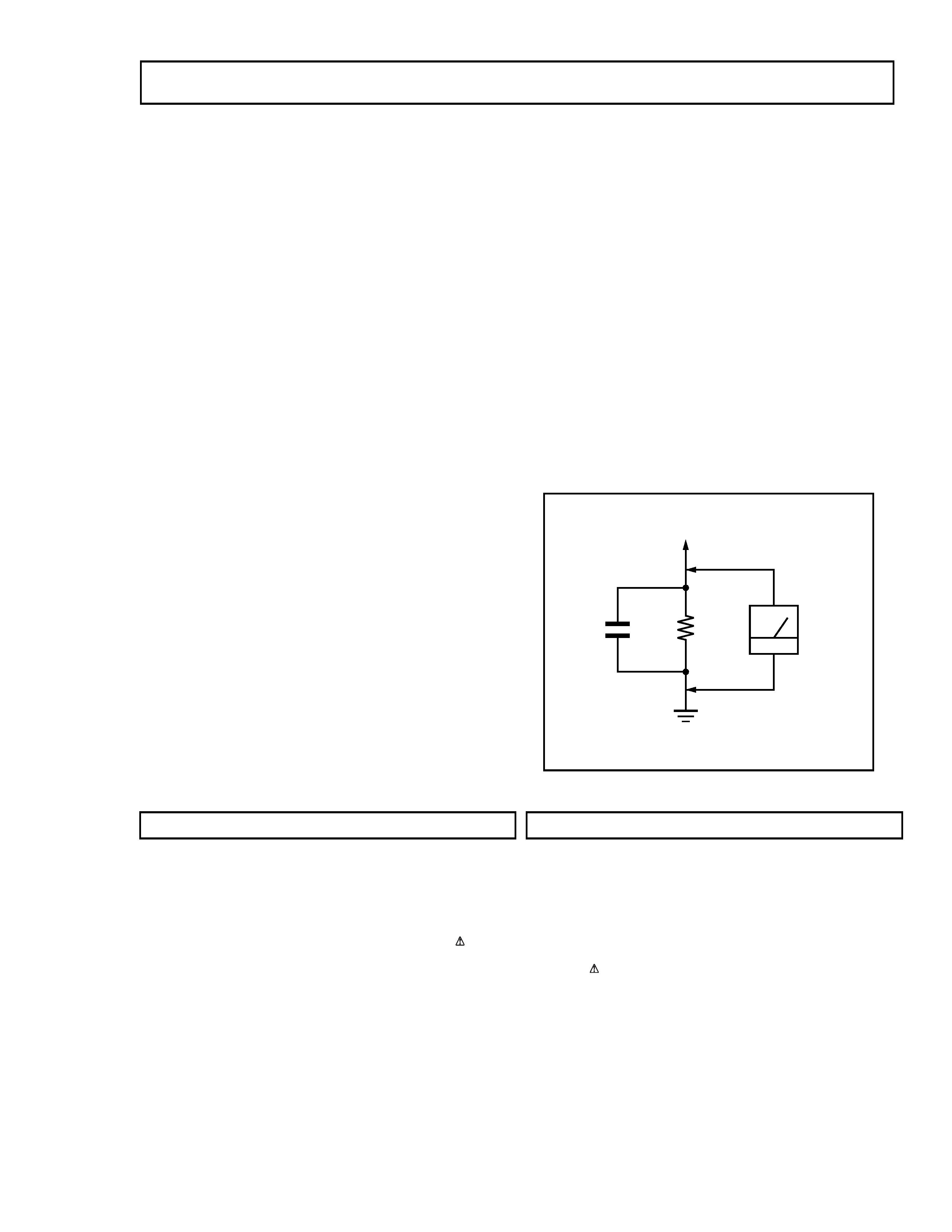
SAFETY CHECK-OUT
LEAKAGE TEST
The AC leakage from any exposed metal part to earth ground
and from all exposed metal parts to any exposed metal part
having a return to chassis, must not exceed 0.5 mA (500
microampere). Leakage current can be measured by any one
of three methods.
WARNING!!
NEVER TURN ON THE POWER IN A CONDITION IN WHICH THE
DEGAUSS COIL HAS BEEN REMOVED.
SAFETY-RELATED COMPONENT WARNING!!
COMPONENTS IDENTIFIED BY SHADING AND MARK
ON THE
SCHEMATIC DIAGRAMS, EXPLODED VIEWS AND IN THE PARTS
LIST ARE CRITICAL FOR SAFE OPERATION. REPLACE THESE
COMPONENTS WITH SONY PARTS WHOSE PART NUMBERS
APPEAR AS SHOWN IN THIS MANUAL OR IN SUPPLEMENTS
PUBLISHED BY SONY. CIRCUIT ADJUSTMENTS THAT ARE
CRITICAL FOR SAFE OPERATION ARE IDENTIFIED IN THIS
MANUAL. FOLLOW THESE PROCEDURES WHENEVER CRITICAL
COMPONENTS ARE REPLACED OR IMPROPER OPERATION IS
SUSPECTED.
After correcting the original service problem, perform
the following safety checks before releasing the set to
the customer:
1. Check the area of your repair for unsoldered or poorly-
soldered connections. Check the entire board surface
for solder splashes and bridges.
2. Check the interboard wiring to ensure that no wires
are "pinched" or contact high-wattage resistors.
3. Check that all control knobs, shields, covers, ground
straps, and mounting hardware have been replaced.
Be absolutely certain that you have replaced all the
insulators.
4. Look for unauthorized replacement parts, particularly
transistors, that were installed during a previous
repair.
Point them out to the customer and
recommend their replacement.
5. Look for parts which, though functioning, show
obvious signs of deterioration. Point them out to the
customer and recommend their replacement.
6. Check the line cords for cracks and abrasion.
Recommend the replacement of any such line cord
to the customer.
7. Check the B+ and HV to see if they are specified
values. Make sure your instruments are accurate; be
suspicious of your HV meter if sets always have low
HV.
8. Check the antenna terminals, metal trim, "metallized"
knobs, screws, and all other exposed metal parts for
AC Leakage. Check leakage as follows.
1. A commercial leakage tester, such as the Simpson 229 or
RCA WT-540A. Follow the manufacturers' instructions to
use these instructions.
2. A battery-operated AC milliammeter. The Data Precision
245 digital multimeter is suitable for this job.
3. Measuring the voltage drop across a resistor by means of
a VOM or battery-operated AC voltmeter. The "limit"
indication is 0.75 V, so analog meters must have an
accurate low voltage scale. The Simpson's 250 and Sanwa
SH-63TRD are examples of passive VOMs that are
suitable. Nearly all battery operated digital multimeters
that have a 2V AC range are suitable. (See Figure A)
Figure A
AVERTISSEMENT!!
NE JAMAIS METTRE SOUS TENSION QUAND LA BOBINE DE
DEMAGNETISATION EST ENLEVEE.
ATTENTION AUX COMPOSANTS RELATIFS A LA SECURITE!!
LES COMPOSANTS IDENTIFIES PAR UNE TRAME ET PAR UNE
MARQUE
SUR LES SCHEMAS DE PRINCIPE, LES VUES
EXPLOSEES ET LES LISTES DE PIECES SONT D'UNE
IMPORTANCE
CRITIQUE
POUR
LA
SECURITE
DU
FONCTIONNEMENT. NE LES REMPLACER QUE PAR DES
COMPOSANTS SONY DONT LE NUMERO DE PIECE EST
INDIQUE DANS LE PRESENT MANUEL OU DANS DES
SUPPLEMENTS PUBLIES PAR SONY. LES REGLAGES DE
CIRCUIT DONT L'IMPORTANCE EST CRITIQUE POUR LA
SECURITE DU FONCTIONNEMENT SONT IDENTIFIES DANS
LE PRESENT MANUEL. SUIVRE CES PROCEDURES LORS DE
CHAQUE REMPLACEMENT DE COMPOSANTS CRITIQUES, OU
LORSQU'UN MAUVAIS FONTIONNEMENT SUSPECTE.

-- 4 --
P900
Section
Title
Page
SAFETY CHECK-OUT ............................................................................. 3
1.
DISASSEMBLY
1-1. Cabinet/Shield Removal ............................................... 5
1-2. Service Position ............................................................. 5
1-3. D, A, H and N Board Removal ....................................... 5
1-4. Picture Tube Removal ................................................... 6
2.
SAFETY RELATED ADJUSTMENT .................................................. 7
3.
ADJUSTMENTS .............................................................................. 8
4.
DIAGRAMS
4-1. Block Diagram ............................................................. 11
4-2. Circuit Boards Location ............................................... 14
4-3. Schematic Diagrams and Printed Wiring Boards ...... 14
1. D Board - Schematic Diagram .............................. 15
2. H Board - Schematic Diagram .............................. 21
3. N Board - Schematic Diagram .............................. 22
4. A Board - Schematic Diagram ............................... 23
4-4. Semiconductors .......................................................... 26
5.
EXPLODED VIEWS
5-1. Chassis ....................................................................... 28
5-2. Packing Materials ........................................................ 29
6.
ELECTRICAL PARTS LIST ............................................................ 30
TABLE OF CONTENTS
-- 5 --
P900
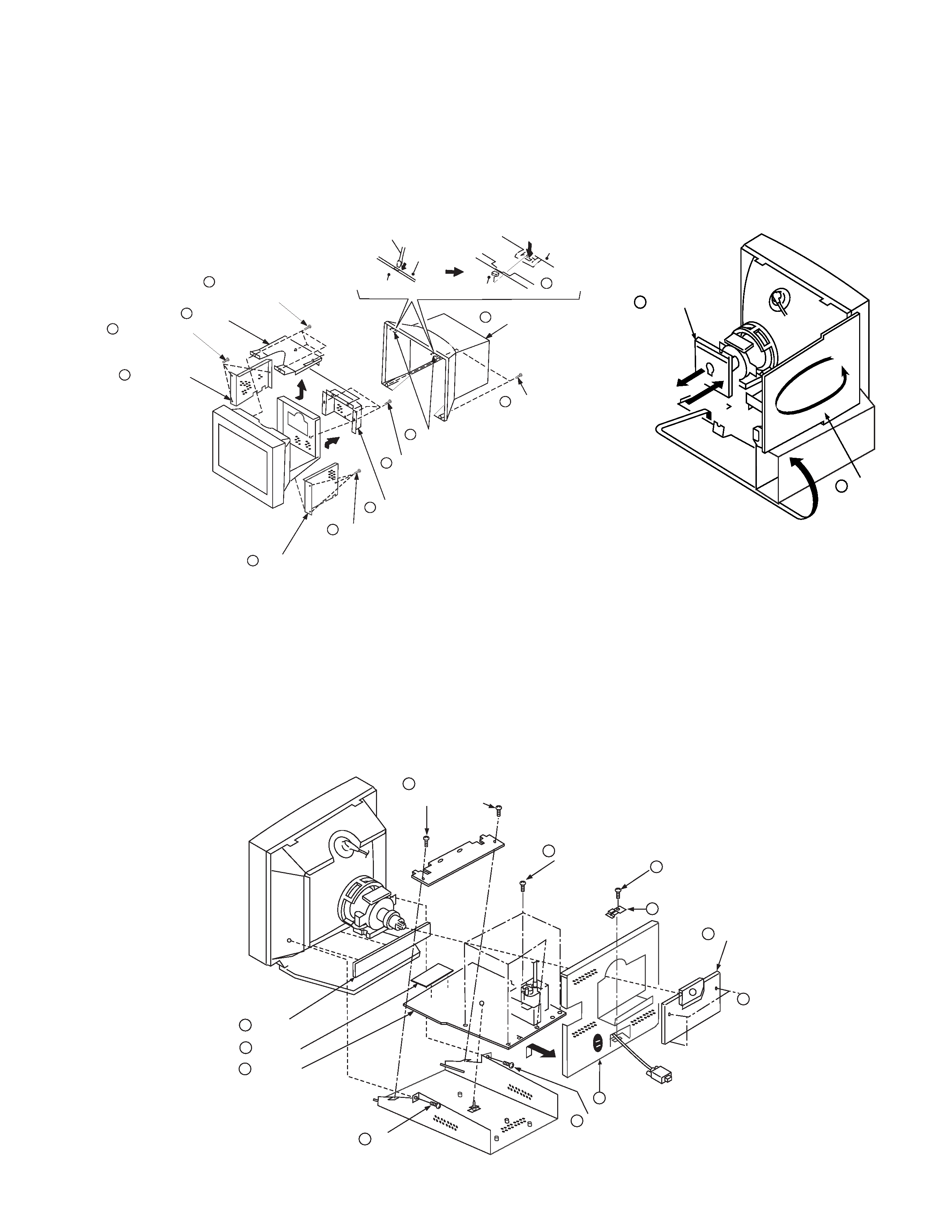
1
2
A board
D board
rotate
180º
1-3. D, A, H and N BOARD REMOVAL
1-1. CABINET/SHIELD REMOVAL
1-2. SERVICE POSITION
SECTION 1
DISASSEMBLY
1
When the D board is placed in service position, the Safety Earth Wire
(black wire) is disconnected.
2
After service is completed and the D board reinstalled, the Safety Earth
Wire must be reattached to the chassis. This must be confirmed before
any subsequent procedures are attempted.
To remove the rear cover of the unit, press in and unsnap the claw on
the right side of the unit, then press in and unsnap the right claw at the
top of the unit. Repeat this with the claw on the left side and top left
of the unit and remove.
Video shield
Two claws
Three screws
(+BVTT 4 x 8)
Two screws
(+ BVTP 4 x 16)
1
2
6
7
5
4
3
2 Two claws
Four screws
(+ BVTP 4 x 8)
Top cover
Bezel assembly
Bezel assembly
Cabinet
Cabinet
Push in the tip of a screwdriver
about 5mm to unlock the claw.
Cabinet
Three screws
(+BVTT 4 x 8)
8
Three screws
(+BVTT 4 x 8)
8
9 Side cover
9
Side cover
Cable bracket
D board
Five screws
(BVTP 3 x 8)
2
6
4
8
Holder
5
A board
N board
10
H board
11
One screw
(BVTT 4 x 8)
3
Three screws
(BVTT 4 x 8)
1
Two screws
(BVTT 4 x 8)
9
One screw
(BVTT 4 x 8)
7
One screw
(BVTT 4 x 8)
7