
SPECIFICATIONS
D99
Picture tube
Video image area
Resolution
Standard image area
Input signal
Video
Sync
0.24-0.25 mm aperture grill pitch
17 inches measured diagonally
90-degree deflection
(16" maximum viewing image)
Approx. 327 X 243 mm (w/h)
(127/8 x 95/8 inches)
Horizontal: Max. 1600 dots
Vertical: Max. 1200 lines
Approx. 312 x 234 mm (w/h)
(121/4 x 91/4 inches)
Analog RGB (75 ohms typical)
0.7 Vp-p, ±5%, Positive
Separate HD/VD,
TTL Polarity Free
External Composite,
TTL Polarity Free (2K ohms impedance)
Sync on Green
Power Consumption
Maximum
Nominal
Deflection frequency
AC input voltage / current
Dimensions
Mass
CHASSIS
130 W
95 W
Horizontal: 30 to 92 KHz
Vertical: 48 to 120 Hz
100 to 120 V, 50/60 Hz, 1.7A
220 to 240V, 50/60Hz, 0.9A
404 x 428 x 424 mm (w/h/d)
(159/10 x 167/8 x 167/10 inches)
Approx. 19.2 kg (42 lb 11 oz.)
SERVICE MANUAL
P700
P700
US Model
Canadian Model
Chassis No. SCC-L29P-A
Design and specifications are subject to change without notice.
TRINITRON COLOR MONITOR
compaq Front.8.30.p65
8/31/99, 8:17 AM
1
-- 2 --
P700
POWER MANAGEMENT
The power saving mode complies with the VESA Display Power Management Signaling standard.
Each state of power management shall be activated by the host computer terminating the appropriate
sync signals. Blanking the video must precede termination of the sync signals. The elapsed time
counter shall also be controlled by the host computer. Reactivation of the monitor shall be accomplished
from the host computer by re-establishing the normal sync signal.
Status
Area of Failure
LED Indication
1 Failure 1
HV or +B
Amber (0.5 second)/Off (0.5 second)
2 Failure 2
Amber (1.5 second)/Off (0.5 second)
3 Failure 3
ABL
Amber (0.5 second)/Off (1.5 second)
4 Aging/Self Test
Amber (0.5 second)/Off (0.5 second)/
Green (0.5 second)/Off (0.5 second)
H Stop or V Stop
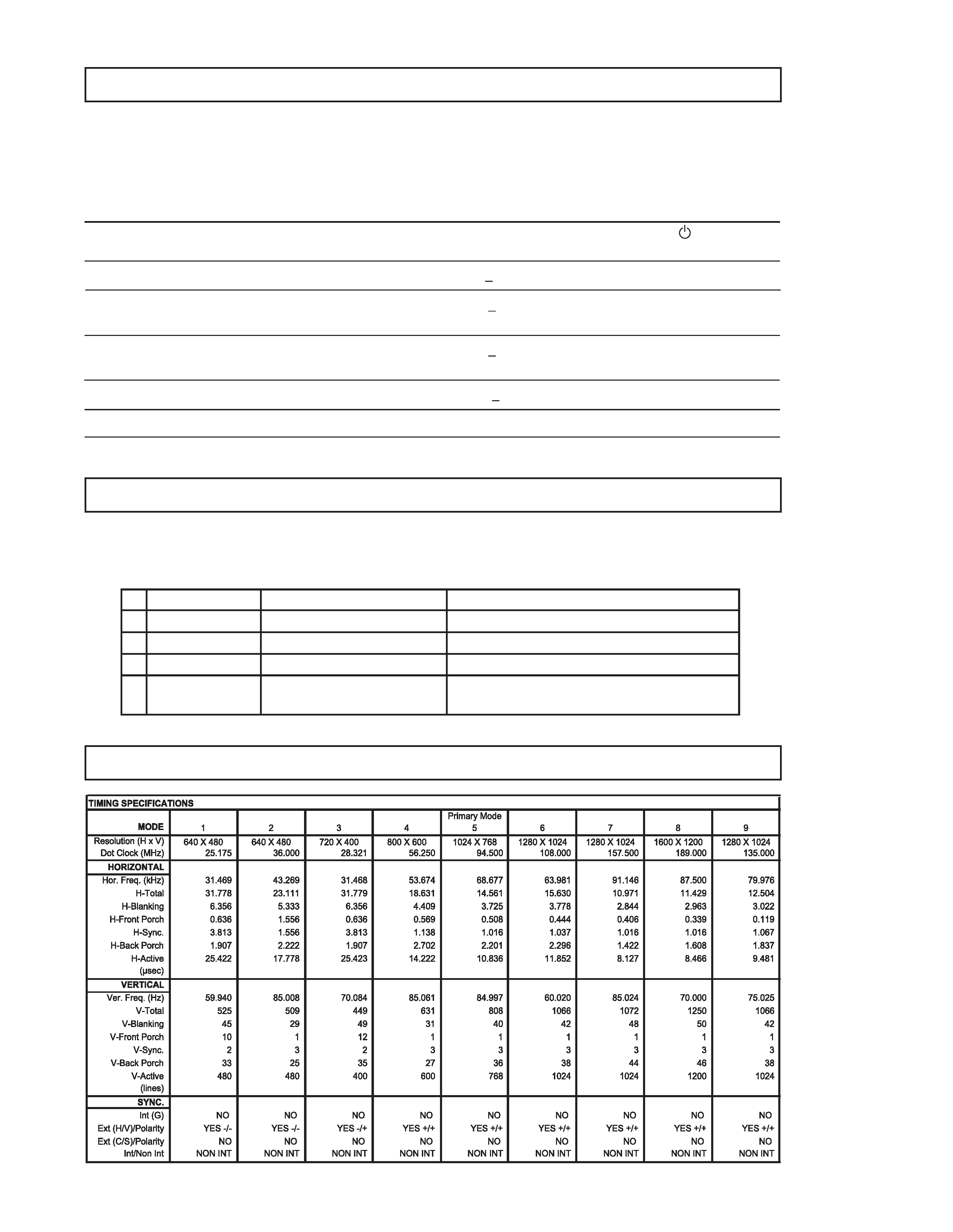
TIMING SPECIFICATION
SELF DIAGNOSIS FUNCTION
When a failure occurs, the STANDBY/TIMER lamp will flash a set number of times to indicate the
possible cause of the problem. If there is more than one error, the lamp will identify the first of the
problem areas.
Power consumption
Screen
Horizontal
Vertical
Power
Recovery time
indicator
mode
(video)
sync signal
sync signal consumption
1
Normal operation
active
yes
yes
< 130 W
--
Green
2
Standby (1st mode)
blank
no
yes
< 15 W
Approx. 3 sec.
Green and Orange
Alternate
3
Suspend (2nd mode)
blank
yes
no
< 15 W
Approx. 3 sec.
Green and Orange
Alternate
4
Active-off (3rd mode)
blank
no
no
< 3 W
Approx. 10 sec.
Orange
5
Power-off
--
--
--
0 W
--
Off

-- 3 --
P700
TABLE OF CONTENTS
Section
Title
Page
Safety Check Out Instructions ............................................................... 4
1. GENERAL .................................................................................. 5
2. DISASSEMBLY
2-1. Cabinet Removal .......................................................... 10
2-2. Service Position ........................................................... 10
2-3. A and D Board Removal .............................................. 10
2-4. Picture Tube Removal .................................................. 11
3. SAFETY RELATED ADJUSTMENTS ............................. 12
4. ADJUSTMENTS ..................................................................... 13
5. DIAGRAMS
5-1-1.Block Diagram (1/2) ..................................................... 19
5-1-2.Block Diagram (2/2) ..................................................... 21
5-2. Circuit Boards Location ................................................ 23
5-3. Schematic Diagrams and Printed Wiring Boards ........ 23
1. A Board - Schematic Diagram ................................ 25
2. D Board - Schematic Diagram ................................ 30
5-4. Semiconductors ........................................................... 37
6. EXPLODED VIEWS
6-1. Chassis ......................................................................... 38
6-2. Packing Materials ......................................................... 39
7. ELECTRICAL PARTS LIST ................................................ 41
-- 4 --
P700
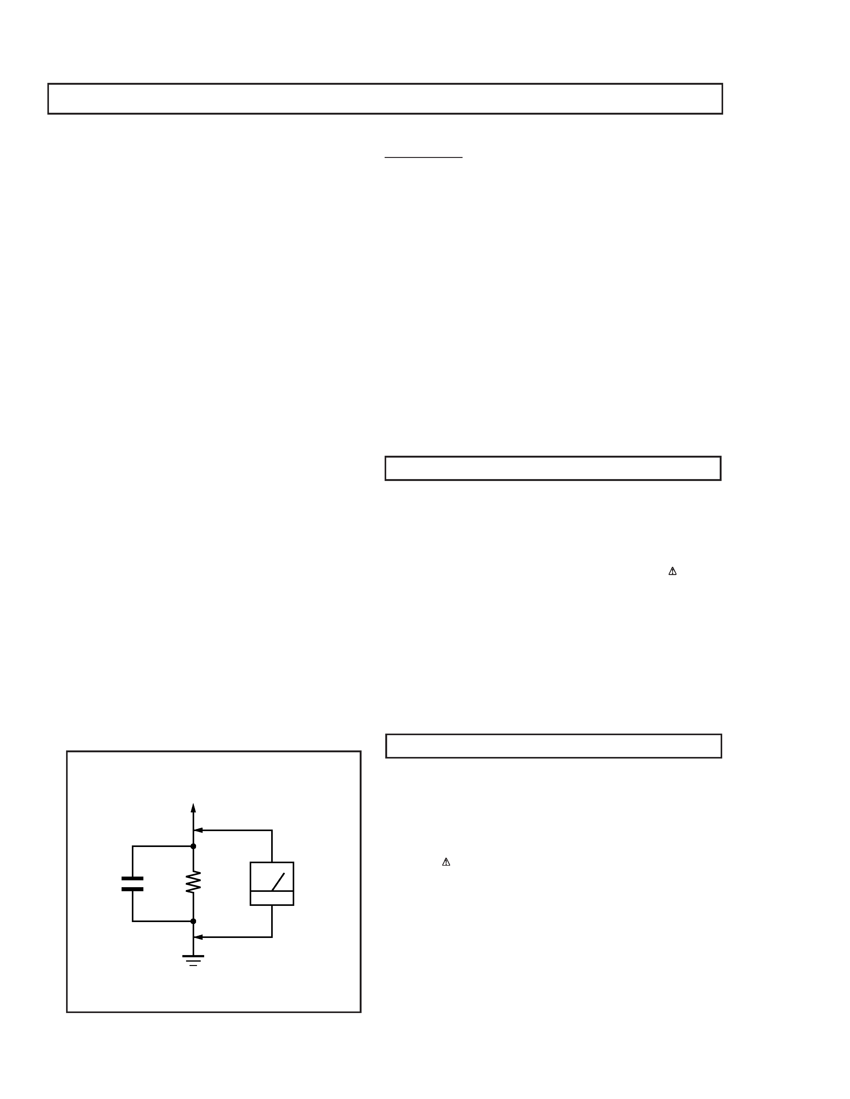
1.5 k
0.15 µF
AC
Voltmeter
(0.75 V)
To Exposed Metal
Parts on Set
Earth Ground
SAFETY CHECK-OUT
After correcting the original service problem, perform the
following safety checks before releasing the set to the
customer:
Leakage Test
The AC leakage from any exposed metal part to earth ground
and from all exposed metal parts to any exposed metal part
having a return to chassis, must not exceed 0.5 mA (500
microampere). Leakage current can be measured by any one
of three methods:
WARNING!!
NEVER TURN ON THE POWER IN A CONDITION IN WHICH THE
DEGAUSS COIL HAS BEEN REMOVED.
SAFETY-RELATED COMPONENT WARNING!!
COMPONENTS IDENTIFIED BY SHADING AND MARK
ON THE
SCHEMATIC DIAGRAMS, EXPLODED VIEWS AND IN THE PARTS
LIST ARE CRITICAL FOR SAFE OPERATION. REPLACE THESE
COMPONENTS WITH SONY PARTS WHOSE PART NUMBERS
APPEAR AS SHOWN IN THIS MANUAL OR IN SUPPLEMENTS
PUBLISHED BY SONY. CIRCUIT ADJUSTMENTS THAT ARE
CRITICAL FOR SAFE OPERATION ARE IDENTIFIED IN THIS
MANUAL. FOLLOW THESE PROCEDURES WHENEVER
CRITICAL COMPONENTS ARE REPLACED OR IMPROPER
OPERATION IS SUSPECTED.
AVERTISSEMENT!!
NE JAMAIS METTRE SOUS TENSION QUAND LA BOBINE DE
DEMAGNETISATION EST ENLEVEE.
ATTENTION AUX COMPOSANTS RELATIFS A LA SECURITE!!
LES COMPOSANTS IDENTIFIES PAR UNE TRAME ET PAR UNE
MARQUE
SUR LES SCHEMAS DE PRINCIPE, LES VUES
EXPLOSEES ET LES LISTES DE PIECES SONT D'UNE
IMPORTANCE
CRITIQUE
POUR
LA
SECURITE
DU
FONCTIONNEMENT. NE LES REMPLACER QUE PAR DES
COMPOSANTS SONY DONT LE NUMERO DE PIECE EST
INDIQUE DANS LE PRESENT MANUEL OU DANS DES
SUPPLEMENTS PUBLIES PAR SONY. LES REGLAGES DE
CIRCUIT DONT L'IMPORTANCE EST CRITIQUE POUR LA
SECURITE DU FONCTIONNEMENT SONT IDENTIFIES DANS LE
PRESENT MANUEL. SUIVRE CES PROCEDURES LORS DE
CHAQUE REMPLACEMENT DE COMPOSANTS CRITIQUES, OU
LORSQU'UN MAUVAIS FONTIONNEMENT SUSPECTE.
1. Check the area of your repair for unsoldered or poorly
soldered connections. Check the entire board surface
for solder splashes and bridges.
2. Check the interboard wiring to ensure that no wires
are "pinched" or contact high-wattage resistors.
3. Check that all control knobs, shields, covers, ground
straps, and mounting hardware have been replaced.
Be absolutely certain that you have replaced all the
insulators.
4. Look for unauthorized replacement parts, particularly
transistors, that were installed during a previous repair.
Point them out to the customer and recommend their
replacement.
5. Look for parts which, though functioning, show obvious
signs of deterioration. Point them out to the customer
and recommend their replacement.
6. Check the line cords for cracks and abrasion.
Recommend the replacement of any such line cord to
the customer.
7. Check the B+ and HV to see if they are specified values.
Make sure your instruments are accurate; be suspicious
of your HV meter if sets always have low HV.
8. Check the antenna terminals, metal trim, "metallized"
knobs, screws, and all other exposed metal parts for
AC leakage. Check leakage as described below.
1. A commercial leakage tester, such as the Simpson 229 or
RCA WT-540A. Follow the manufacturers' instructions to
use these instructions.
2. A battery-operated AC milliammeter. The Data Precision
245 digital multimeter is suitable for this job.
3. Measuring the voltage drop across a resistor by means of
a VOM or battery-operated AC voltmeter. The "limit"
indication is 0.75 V, so analog meters must have an
accurate low voltage scale. The Simpson's 250 and Sanwa
SH-63Trd are examples of passive VOMs that are suitable.
Nearly all battery operated digital multimeters that have a
2V AC range are suitable. (See Figure A)
Figure A
-- 5 --
P700
SECTION
1
GENERAL
Precautions
Do
no
tin
sta
ll
t
h
em
o
n
ito
rin
th
efo
llowi
ng
pl
a
ce
s:
·
o
n
sur
fa
c
es
(
rugs
,bl
a
nke
ts
,et
c.
)or
ne
ar
mat
er
ia
ls
(
cu
rt
a
in
s,
d
ra
p
er
ie
s)
th
a
tm
a
y
b
loc
k
th
e
ve
n
tila
tio
n
ho
le
s
·
n
e
ar
hea
tso
urce
s
su
ch
a
sradi
at
o
rs
o
r
a
ir
d
u
ct
s,
or
i
n
a
pl
ac
e
su
bj
ect
t
o
di
rec
tsu
nl
ig
h
t
·
in
a
pl
ac
esub
ject
t
o
seve
re
t
e
mpe
rat
ure
ch
ang
es
·
in
a
pl
ac
esub
ject
t
o
mech
an
ic
al
v
ibrat
io
n
or
sho
ck
·
o
n
an
un
st
ab
le
su
rface
·
n
ea
re
q
uip
m
en
tw
h
ic
h
ge
n
e
ra
te
sm
agn
et
is
m,
s
u
ch
a
sa
tr
an
sf
o
rm
er
or
hi
gh
vo
lta
g
e
po
w
e
rlin
es
·
n
e
ar
or
on
a
n
electrically
c
h
arg
ed
me
ta
lsu
rface
·
C
lean
th
escree
n
wi
th
a
soft
cl
ot
h.
If
y
o
u
use
a
g
la
ss
cl
ean
in
g
li
q
u
id
,
d
o
no
t
u
se
an
y
t
ype
o
fcl
ean
er
con
ta
in
in
g
a
n
an
ti
-st
at
ic
sol
uti
o
n
or
sim
ila
ra
d
d
itiv
ea
sth
is
m
a
y
sc
ra
tc
h
t
h
esc
re
e
n
's
co
at
ing.
·
D
o
n
o
tr
ub,
t
o
u
ch,
or
t
ap
t
h
e
su
rf
ace
o
fth
escr
ee
n
wi
th
sha
rp
or
ab
ra
si
ve
i
te
ms
suc
h
a
sa
ba
ll
po
in
tpe
n
or
s
cr
ewd
ri
v
er
.T
h
is
ty
pe
of
co
nt
ac
tma
y
r
esu
lt
i
n
a
scr
a
tc
hed
p
ict
ur
et
u
b
e.
·
C
le
an
the
ca
b
in
et
,pa
ne
lan
d
co
n
trol
swith
a
soft
cl
oth
li
gh
tly
m
o
ist
e
n
ed
wi
th
a
m
ild
de
te
rg
e
n
tso
lut
ion
.
D
o
n
o
tu
se
a
n
y
typ
eo
f
ab
ra
si
ve
p
ad,
sco
ur
in
g
pow
der
or
so
lv
en
t,
suc
h
as
al
co
ho
lo
r
be
nze
ne.
Wh
e
n
y
o
u
tra
n
spo
rt
th
is
m
o
nito
rfo
rre
p
a
ir
or
ship
m
e
n
t,
use
th
e
or
igin
al
c
ar
ton
a
n
d
p
ac
k
in
g
m
ate
ria
ls.
·
Use
th
esu
p
p
lied
p
o
wer
co
rd
.If
y
o
u
u
se
a
d
ifferen
t
p
o
we
r
c
o
rd
,
be
su
re
th
a
tit
i
sc
o
m
p
atib
le
wit
h
y
o
u
rlo
ca
lp
o
we
rsu
pp
ly.
For
th
ecu
stom
ers
in
th
eUS
If
y
o
u
d
o
no
tu
se
the
a
p
pro
pri
a
te
c
o
rd,
th
is
m
o
n
ito
rwill
no
t
co
n
for
m
t
o
m
and
at
or
y
F
C
C
St
an
da
rd
s.
·
B
efo
re
di
sco
nn
ect
in
g
th
epo
wer
cord
,wai
tat
l
e
ast
30
se
con
ds
af
te
rtu
rnin
g
off
the
po
we
r
to
a
llow
t
h
esta
tic
e
le
ctric
ity
o
n
the
sc
re
en's
su
rface
to
d
is
cha
rg
e.
·
A
fte
rth
epo
we
ris
tu
rn
e
d
o
n
,th
e
sc
re
en
is
de
m
agn
etiz
e
d
(de
g
au
ss
ed)
fo
ra
b
ou
t3
s
eco
nd
s.
T
h
is
ge
ne
ra
te
sa
s
tro
ng
ma
gn
et
ic
f
iel
d
a
roun
d
th
e
sc
reen
,whi
c
h
may
a
ff
e
ct
d
at
a
st
or
e
d
on
ma
gn
et
ic
t
a
pes
a
n
d
di
sks
p
laced
ne
ar
t
h
emo
ni
to
r.
Be
su
re
t
o
ke
ep
ma
gn
et
ic
re
cord
ing
eq
ui
p
m
en
t,
t
ape
s
a
n
d
d
isks
awa
y
from
t
h
e
m
o
n
ito
r.
Installat
ion
Maintenance
T
ranspo
rtat
ion
W
a
rnin
g
on
P
o
wer
Conn
ection
T
h
eequ
ipme
nt
sho
ul
d
b
ei
n
st
al
led
n
ear
an
ea
si
ly
acce
ssi
bl
e
o
u
tle
t.
Ex
ample
of
pl
ug
types
for
100
t
o
120
V
AC
for
200
to
240
V
A
C
The
instructions
giv
en
are
par
tial
abstracts
from
the
Oper
ating
Instr
uction
Man
ual.
The
page
n
umbers
sho
wn
reflect
those
of
the
Oper
ating
Instr
uction
Man
u
al
4
Ge
tting
S
ta
rted
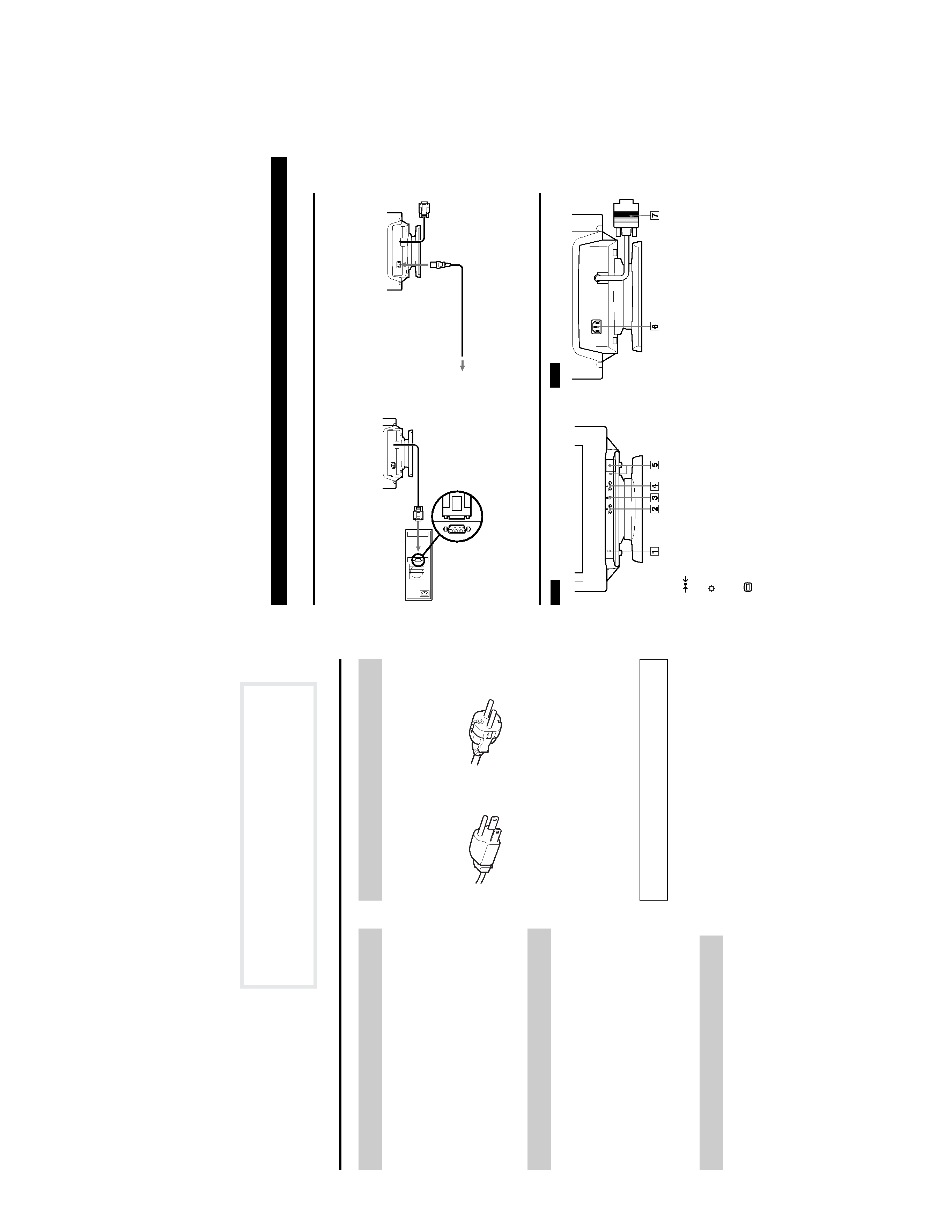
Setup
Co
nne
ct
th
emon
it
o
rt
o
yo
ur
com
pu
te
r
sy
st
em.
Th
is
m
o
n
ito
rwill
syn
cto
pl
a
tf
o
rm
sru
nn
ing
a
th
o
riz
on
ta
lfre
qu
en
ci
es
b
e
tw
ee
n
30
a
n
d
8
5
kHz
.
Step
1
Ma
k
e
s
u
re
t
h
e
c
o
mp
ut
er
s
y
st
em
i
ssw
it
ch
ed
o
ff
an
d
a
tt
ac
h
th
evi
de
o
si
gn
al
c
a
b
le
to
th
ev
ide
o
ou
tp
ut
of
the
c
o
mp
ut
er
.
Step
2
M
ake
sur
et
h
e
c
o
mp
ut
er
i
sswi
tc
hed
of
fand
a
tta
ch
t
h
e
po
we
rc
o
rd
to
th
em
o
n
ito
r.
Th
e
n
,
a
tt
a
ch
th
e
oth
er
e
n
d
o
f
th
e
p
o
we
rco
rd
to
a
p
o
wer
o
u
tl
e
t.
Step
3
S
w
it
c
h
on
t
h
emo
ni
to
rand
com
put
e
r.
Step
4
A
d
ju
st
th
e
u
ser
co
nt
ro
ls
ac
co
rd
in
g
to
yo
ur
pe
rs
on
al
p
referen
ce.
Inst
a
ll
a
tion
is
c
o
m
p
le
te
.
Parts
and
Controls
1
(RESET)
button
(pa
ges
6
,
9
)
Th
is
bu
tto
n
re
se
ts
t
h
ea
d
justm
ents
to
the
fa
ct
o
ry
se
tt
ing
s.
2
(BRIGHTNESS)
(
v/V
)but
tons
(page
5)
Th
e
se
b
u
tt
on
sa
d
ju
st
th
ep
ic
ture
b
rig
htn
es
s
a
n
d
fun
ctio
n
a
sth
e
(v/V
)bu
tto
ns
wh
en
a
d
ju
st
ing
o
the
r
ite
m
s.
3
(M
ENU)
b
u
tton
(page
6)
Th
is
bu
tto
n
disp
la
ys
t
h
eM
ENU
OSD.
4
6
(CONTRAST)
(B/b
)bu
ttons
(pag
e
5
)
T
h
e
se
bu
tt
o
n
sad
ju
st
t
h
eco
nt
rast
an
d
fun
ct
io
n
as
t
h
e
(B/
b
)
bu
tto
ns
wh
en
a
d
ju
st
ing
o
the
r
ite
m
s.
5
1
(PO
WER)
s
w
itc
h
a
nd
in
dica
tor
Thi
s
bu
tto
n
turn
sth
em
o
n
ito
ron
a
n
d
o
ff.
The
in
d
ic
ato
rli
gh
ts
up
g
re
en
whe
n
th
e
m
o
nit
or
i
s
on
,a
n
d
lig
h
ts
u
p
gr
e
en
an
d
or
a
n
g
ew
hen
t
h
e
mon
it
o
r
is
i
n
P
owe
rS
av
ing
mo
de
.
6
AC
IN
co
nnec
tor
T
h
is
c
onn
ect
o
r
p
rov
id
es
A
C
po
w
er
to
th
emo
ni
to
r.
7
Video
inpu
tco
nnec
tor
(HD15
)(pa
ge
5
)
T
h
is
c
onn
ect
o
r
in
pu
ts
R
G
B
vi
d
eo
si
gn
al
san
d
SYN
C
si
g
n
al
s.
Computer
to
the
v
ide
o
output
to
a
power
out
let
P
ower
cord
Fr
on
t
Re
ar
3